oil pressure CHRYSLER VOYAGER 2023 Owners Manual
[x] Cancel search | Manufacturer: CHRYSLER, Model Year: 2023, Model line: VOYAGER, Model: CHRYSLER VOYAGER 2023Pages: 256, PDF Size: 13.97 MB
Page 6 of 256
4
MULTIMEDIA
UCONNECT SYSTEMS ..................................................... 104
CYBERSECURITY ............................................................. 104
UCONNECT SETTINGS...................................................... 105
Customer Programmable Features ........................ 105
RADIO OPERATION AND MOBILE PHONES .................. 120 Regulatory And Safety Information .......................... 120
SAFETY
SAFETY FEATURES........................................................... 121Anti-Lock Brake System (ABS) ................................. 121Rear Seat Reminder Alert (RSRA) ............................ 121
Electronic Brake Control (EBC) System .................. 122
AUXILIARY DRIVING SYSTEMS ...................................... 126 Blind Spot Monitoring (BSM) — If Equipped ............ 126Forward Collision Warning (FCW) With
Mitigation — If Equipped ........................................... 129
Tire Pressure Monitoring
System (TPMS) .......................................................... 131
OCCUPANT RESTRAINT SYSTEMS ................................ 134 Occupant Restraint Systems Features ................... 134Important Safety Precautions .................................. 134Seat Belt Systems .................................................... 135
Supplemental Restraint Systems (SRS) .................. 143Child Restraints ......................................................... 153 SAFETY TIPS .................................................................... 167
Transporting Passengers ......................................... 167
Transporting Pets .................................................... 167
Connected Vehicles .................................................. 167Safety Checks You Should Make Inside
The Vehicle ............................................................... 167Periodic Safety Checks You Should Make
Outside The Vehicle .................................................. 168Exhaust Gas ............................................................. 169
Carbon Monoxide Warnings ..................................... 169IN CASE OF EMERGENCY
HAZARD WARNING FLASHERS ..................................... 170
SOS AND ASSIST MIRROR — IF EQUIPPED ................. 170
JACKING AND TIRE CHANGING —
IF EQUIPPED .................................................................... 173 Preparations For Jacking ......................................... 173
Jack And Spare Tire Location................................... 174Equipment Removal ................................................ 174
Jacking Instructions.................................................. 175Road Tire Installation ............................................... 178
Portable Air Compressor — If Equipped .................. 179
Return Inflatable Spare Tire..................................... 180
TIRE SERVICE KIT — IF EQUIPPED ................................. 180
JUMP STARTING............................................................... 185 Preparations For Jump Start .................................... 185Jump Starting Procedure.......................................... 186 REFUELING IN EMERGENCY – IF EQUIPPED ...............187
IF YOUR ENGINE OVERHEATS......................................... 187
MANUAL PARK RELEASE ...............................................188
FREEING A STUCK VEHICLE ........................................... 189
TOWING A DISABLED VEHICLE.......................................190
ENHANCED ACCIDENT RESPONSE
SYSTEM (EARS) ...............................................................191
EVENT DATA RECORDER (EDR)......................................191
SERVICING AND MAINTENANCE
SCHEDULED SERVICING ................................................. 192 Maintenance Plan ..................................................... 193
ENGINE COMPARTMENT ................................................. 195 3.6L Engine................................................................ 195
Checking Oil Level ..................................................... 196Adding Washer Fluid ................................................ 196
Maintenance-Free Battery ........................................ 196Pressure Washing ..................................................... 197
VEHICLE MAINTENANCE ................................................. 197 Engine Oil .................................................................. 197
Engine Oil Filter ......................................................... 197
Engine Air Cleaner Filter .......................................... 198
Accessory Drive Belt Inspection ............................... 198Air Conditioner Maintenance .................................... 199
Body Lubrication........................................................ 200
Windshield Wiper Blades .......................................... 201
23_RUV_OM_EN_US_t.book Page 4
Page 10 of 256
8
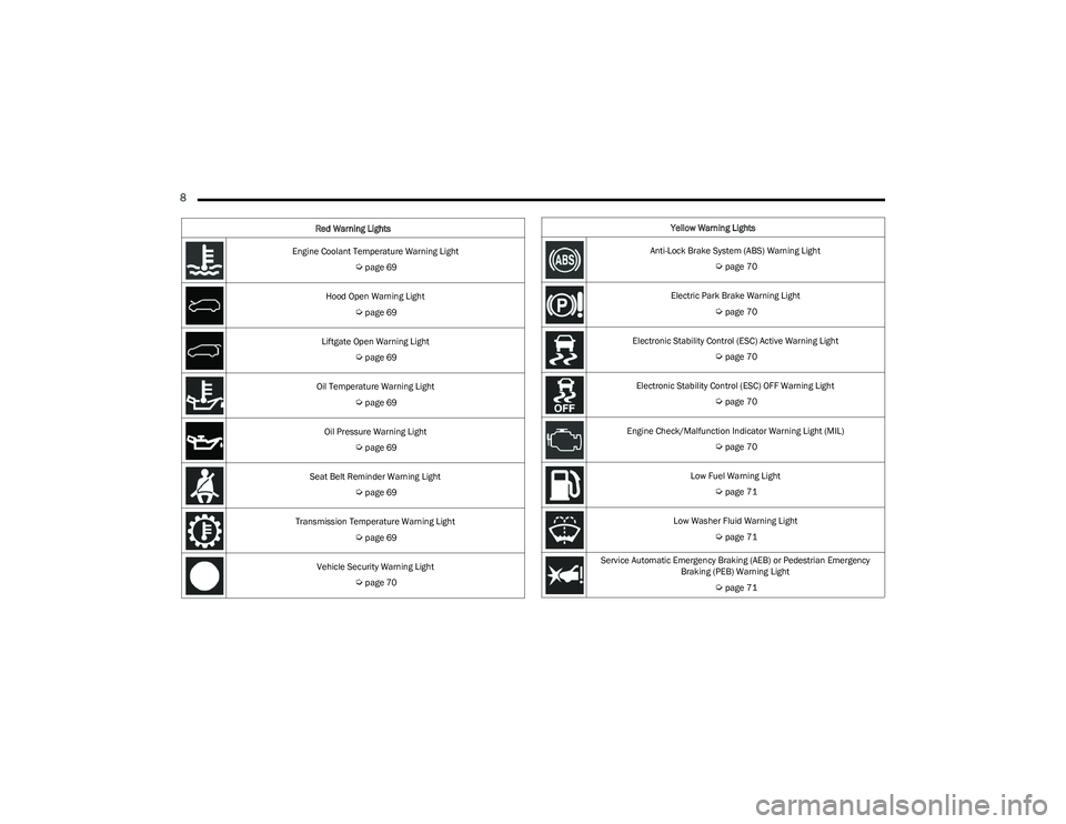
Engine Coolant Temperature Warning Light
Úpage 69
Hood Open Warning Light
Úpage 69
Liftgate Open Warning Light
Úpage 69
Oil Temperature Warning Light
Úpage 69
Oil Pressure Warning Light
Úpage 69
Seat Belt Reminder Warning Light
Úpage 69
Transmission Temperature Warning Light
Úpage 69
Vehicle Security Warning Light
Úpage 70
Red Warning Lights
Yellow Warning Lights
Anti-Lock Brake System (ABS) Warning Light
Úpage 70
Electric Park Brake Warning Light
Úpage 70
Electronic Stability Control (ESC) Active Warning Light
Úpage 70
Electronic Stability Control (ESC) OFF Warning Light
Úpage 70
Engine Check/Malfunction Indicator Warning Light (MIL)
Úpage 70
Low Fuel Warning Light
Úpage 71
Low Washer Fluid Warning Light
Úpage 71
Service Automatic Emergency Braking (AEB) or Pedestrian Emergency Braking (PEB) Warning Light
Úpage 71
23_RUV_OM_EN_US_t.book Page 8
Page 66 of 256
64GETTING TO KNOW YOUR INSTRUMENT PANEL
KEYSENSE CLUSTER MESSAGES —
I
F EQUIPPED
When the KeySense key is in use there will be:
Continuous, dedicated telltale
Unique Display Splash Screen
With KeySense in use there will be multiple associated
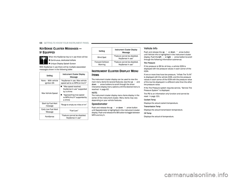
messages shown in the following table:
INSTRUMENT CLUSTER DISPLAY MENU
I
TEMS
The instrument cluster display can be used to view the
main menu items for several features. Use the up and
down arrow buttons to scroll through the driver
interactive display menu options until the desired menu is
reached
Úpage 62.
NOTE:The instrument cluster display menu items display in the
center of the instrument cluster. Menu items may vary
depending on your vehicle features.
Speedometer
Push and release the up or down arrow button
until Speedometer is highlighted in the instrument cluster
display. Push and release the OK button to toggle between
MPH and km/h.
Vehicle Info
Push and release the up or down arrow button
until Vehicle Info is highlighted in the instrument cluster
display. Push the left or right arrow button to scroll
through the following information submenus:
Tire Pressure
If tire pressure is OK for all tires, a vehicle ICON is
displayed with tire pressure values in each corner of the
ICON.
If one or more tires have low pressure, “Inflate Tire To XX”
is displayed with the vehicle ICON, and the tire pressure
values in each corner of the ICON with the pressure value
of the low tire displayed in a different color than the other
tire pressure value.
If the Tire Pressure system requires service, “Service Tire
Pressure System” is displayed.
Tire PSI is an information only function and cannot be
reset
Úpage 131.
Coolant Temp
Displays the actual coolant temperature.
Transmission Temp
Displays the actual transmission temperature.
Oil Temp
Displays the actual oil temperature.
Setting
Instrument Cluster Display
Message
None – With vehicle ignition ON “KeySense in use. Max vehicle
speed set to xx MPH/or km/h”
Max Vehicle Speed
“Max speed reached.
KeySense in use” supported
by a chime
“Approaching max speed
xx MPH/km/h” supported by
a chime
Start Up Fuel Alert message
“Range to empty xxx miles or km”
Early Low Fuel Alert Message “Fuel Low”
ParkSense “Feature cannot be disabled.
KeySense in use”
Blind Spot “Feature cannot be disabled.
KeySense in use”
Forward Collision Warning “Feature cannot be disabled.
KeySense in use”
Setting
Instrument Cluster Display
Message
23_RUV_OM_EN_US_t.book Page 64
Page 67 of 256
GETTING TO KNOW YOUR INSTRUMENT PANEL65
Oil Pressure
Displays the actual oil pressure.
Oil Life
Displays the remaining engine oil life as a percentage.
To reset the Oil Life, you must hold the OK button.
The “Hold OK to Reset” instruction will be displayed at all
times, but the following conditions will need to be met in
order to reset Oil Life:
The ignition must be in the ON/RUN position
If the conditions are met, holding the OK button will reset
the gauge and the numeric display will return to 100%.
If the conditions are not met, a pop-up message will
display for five seconds, describing the required
conditions, and then the Oil Life screen will reappear.
Battery Voltage
Displays the actual battery voltage.
Engine Hours — If Equipped
Displays the number of hours of engine operation.
Driver Assist — If Equipped
Push and release the up or down arrow button
until the Driver Assist display icon is highlighted in the
instrument cluster display
Úpage 86.
Fuel Economy
Push and release the up or down arrow button
until the Fuel Economy Menu item is highlighted in the
instrument cluster display. The Fuel Economy Menu will
display the following:
Two submenu pages that can be toggled between
using the left and right arrow buttons; one
with Current Value displayed and one without the
Current Value displayed:
Average Fuel Economy (MPG, L/100 km, or km/L)
Range To Empty (miles or km)
Current Fuel Economy (MPG, L/100 km, or km/L)
The Max and Min values will correspond to the
particular engine requirements
Hold OK to reset average fuel eco nomy information.
Trip Info
Push and release the up or down arrow button
until the Trip Menu item is highlighted in the instrument
cluster display. Push the left or right arrow button
to scroll through the Trip A and Trip B submenus. The Trip
information will display the following:
Distance
Average Fuel Economy
Elapsed Time
Hold the OK button to reset feature information.
Stop / Start – If Equipped
Push and release the up or down arrow button
until the Stop/Start menu title is displayed in the
instrument cluster display.
Audio
Push and release the up or down arrow button
until the Audio Menu displays in the instrument cluster
display.
Messages
Push and release the up or down arrow button
until Messages is highlighted in the instrument cluster
display. This feature shows the number of stored warning
messages. Pushing the right arrow button will allow
you to see what the stored messages are.
NOTE:The pop-up messages indicate the status of the system
and/or the conditions that need to be met. Messages
remain in the stored stack until condition is cleared.
Screen Setup
Push and release the up or down arrow button
until the Screen Setup Menu displays in the instrument
cluster display. Push and release the OK button to enter
the submenus. The Screen Setup feature allows you to
change what information is displayed in the instrument
cluster as well as the location that information is
displayed.
NOTE:Based on your vehicles trim level, some of the following
options may not be available.
3
23_RUV_OM_EN_US_t.book Page 65
Page 71 of 256
GETTING TO KNOW YOUR INSTRUMENT PANEL69
NOTE:This light may turn on if the accelerator and brake pedals
are pressed at the same time.
If the light continues to flash when the vehicle is running,
immediate service is required and you may experience
reduced performance, an elevated/rough idle, or engine
stall and your vehicle may require towing. The light will
come on when the ignition is placed in the ON/RUN or
ACC/ON/RUN position and remain on briefly as a bulb
check. If the light does not come on during starting, have
the system checked by an authorized dealer.
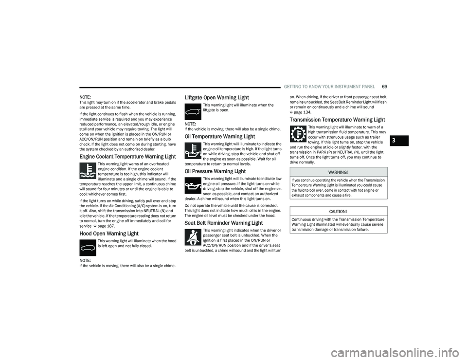
Engine Coolant Temperature Warning Light
This warning light warns of an overheated
engine condition. If the engine coolant
temperature is too high, this indicator will
illuminate and a single chime will sound. If the
temperature reaches the upper limit, a continuous chime
will sound for four minutes or until the engine is able to
cool; whichever comes first.
If the light turns on while driving, safely pull over and stop
the vehicle. If the Air Conditioning (A/C) system is on, turn
it off. Also, shift the transmission into NEUTRAL (N) and
idle the vehicle. If the temperature reading does not return
to normal, turn the engine off immediately and call for
service
Úpage 187.
Hood Open Warning Light
This warning light will illuminate when the hood
is left open and not fully closed.
NOTE:If the vehicle is moving, there will also be a single chime.
Liftgate Open Warning Light
This warning light will illuminate when the
liftgate is open.
NOTE:If the vehicle is moving, there will also be a single chime.
Oil Temperature Warning Light
This warning light will illuminate to indicate the
engine oil temperature is high. If the light turns
on while driving, stop the vehicle and shut off
the engine as soon as possible. Wait for oil
temperature to return to normal levels.
Oil Pressure Warning Light
This warning light will illuminate to indicate low
engine oil pressure. If the light turns on while
driving, stop the vehicle, shut off the engine as
soon as possible, and contact an authorized
dealer. A chime will sound when this light turns on.
Do not operate the vehicle until the cause is corrected.
This light does not indicate how much oil is in the engine.
The engine oil level must be checked under the hood.
Seat Belt Reminder Warning Light
This warning light indicates when the driver or
passenger seat belt is unbuckled. When the
ignition is first placed in the ON/RUN or
ACC/ON/RUN position and if the driver’s seat
belt is unbuckled, a chime will sound and the light will turn on. When driving, if the driver or front passenger seat belt
remains unbuckled, the Seat Belt Reminder Light will flash
or remain on continuously and a chime will sound
Úpage 134.
Transmission Temperature Warning Light
This warning light will illuminate to warn of a
high transmission fluid temperature. This may
occur with strenuous usage such as trailer
towing. If this light turns on, stop the vehicle
and run the engine at idle or slightly faster, with the
transmission in PARK (P) or NEUTRAL (N), until the light
turns off. Once the light turns off, you may continue to
drive normally.
WARNING!
If you continue operating the vehicle when the Transmission
Temperature Warning Light is illuminated you could cause
the fluid to boil over, come in contact with hot engine or
exhaust components and cause a fire.
CAUTION!
Continuous driving with the Transmission Temperature
Warning Light illuminated will eventually cause severe
transmission damage or transmission failure.
3
23_RUV_OM_EN_US_t.book Page 69
Page 170 of 256
168SAFETY
(Continued)
PERIODIC SAFETY CHECKS YOU SHOULD
M
AKE OUTSIDE THE VEHICLE
Tires
Examine tires for excessive tread wear and uneven wear
patterns. Check for stones, nails, glass, or other objects
lodged in the tread or sidewall. Inspect the tread for cuts
and cracks. Inspect sidewalls for cuts, cracks, and bulges.
Check the lug nut/bolt torque for tightness. Check the
tires (including spare) for proper cold inflation pressure.
Lights
Have someone observe the operation of brake lights and
exterior lights while you work the controls. Check turn
signal and high beam indicator lights on the instrument
panel.
Door Latches
Check for proper closing, latching, and locking.
Fluid Leaks
Check area under the vehicle after overnight parking for
fuel, coolant, oil, or other fluid leaks. Also, if gasoline
fumes are detected or if fuel or brake fluid leaks are
suspected, the cause should be located and corrected
immediately.
WARNING!
An improperly attached, damaged, folded, or stacked
floor mat, or damaged floor mat fasteners may cause
your floor mat to interfere with the accelerator, brake, or
clutch pedals and cause a loss of vehicle control. To
prevent SERIOUS INJURY or DEATH:
ALWAYS securely attach your floor mat
using the floor mat fasteners. DO NOT
install your floor mat upside down or turn
your floor mat over. Lightly pull to confirm
mat is secured using the floor mat fasteners on a
regular basis.
ALWAYS REMOVE THE EXISTING FLOOR
MAT FROM THE VEHICLE before installing
any other floor mat. NEVER install or stack
an additional floor mat on top of an
existing floor mat.
ONLY install floor mats designed to fit your vehicle.
NEVER install a floor mat that cannot be properly
attached and secured to your vehicle. If a floor mat needs
to be replaced, only use a FCA approved floor mat for the
specific make, model, and year of your vehicle.
ONLY use the driver’s side floor mat on the driver’s side
floor area. To check for interference, with the vehicle
properly parked with the engine off, fully depress the
accelerator, the brake, and the clutch pedal (if present) to
check for interference. If your floor mat interferes with the
operation of any pedal, or is not secure to the floor,
remove the floor mat from the vehicle and place the floor
mat in your trunk.
ONLY use the passenger’s side floor mat on the
passenger’s side floor area.
ALWAYS make sure objects cannot fall or slide into
the driver’s side floor area when the vehicle is
moving. Objects can become trapped under acceler -
ator, brake, or clutch pedals and could cause a loss
of vehicle control.
NEVER place any objects under the floor mat (e.g.,
towels, keys, etc.). These objects could change the
position of the floor mat and may cause interference
with the accelerator, brake, or clutch pedals.
If the vehicle carpet has been removed and
re-installed, always properly attach carpet to the floor
and check the floor mat fasteners are secure to the
vehicle carpet. Fully depress each pedal to check for
interference with the accelerator, brake, or clutch
pedals then re-install the floor mats.
It is recommended to only use mild soap and water
to clean your floor mats. After cleaning, always check
your floor mat has been properly installed and is
secured to your vehicle using the floor mat fasteners
by lightly pulling mat.
WARNING!
23_RUV_OM_EN_US_t.book Page 168
Page 181 of 256
IN CASE OF EMERGENCY179
PORTABLE AIR COMPRESSOR —
I
F EQUIPPED
Your vehicle may be equipped with a Portable Air
Compressor. Use the Portable Air Compressor located in
the side compartment of the cargo area to inflate the
inflatable tire to 60 psi (4.2 Bar).
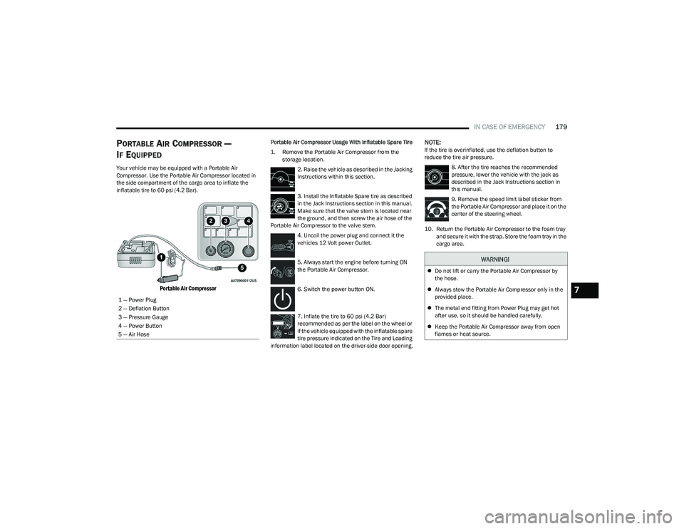
Portable Air Compressor
Portable Air Compressor Usage With Inflatable Spare Tire
1. Remove the Portable Air Compressor from the
storage location.
2. Raise the vehicle as described in the Jacking
Instructions within this section.
3. Install the Inflatable Spare tire as described
in the Jack Instructions section in this manual.
Make sure that the valve stem is located near
the ground, and then screw the air hose of the
Portable Air Compressor to the valve stem.
4. Uncoil the power plug and connect it the
vehicles 12 Volt power Outlet.
5. Always start the engine before turning ON
the Portable Air Compressor.
6. Switch the power button ON.
7. Inflate the tire to 60 psi (4.2 Bar)
recommended as per the label on the wheel or
if the vehicle equipped with the inflatable spare
tire pressure indicated on the Tire and Loading
information label located on the driver-side door opening.NOTE:If the tire is overinflated, use the deflation button to
reduce the tire air pressure.
8. After the tire reaches the recommended
pressure, lower the vehicle with the jack as
described in the Jack Instructions section in
this manual.
9. Remove the speed limit label sticker from
the Portable Air Compressor and place it on the
center of the steering wheel.
10. Return the Portable Air Compressor to the foam tray and secure it with the strap. Store the foam tray in the
cargo area.
1 — Power Plug
2 — Deflation Button
3 — Pressure Gauge
4 — Power Button
5 — Air Hose
WARNING!
Do not lift or carry the Portable Air Compressor by
the hose.
Always stow the Portable Air Compressor only in the
provided place.
The metal end fitting from Power Plug may get hot
after use, so it should be handled carefully.
Keep the Portable Air Compressor away from open
flames or heat source.
7
23_RUV_OM_EN_US_t.book Page 179
Page 185 of 256
IN CASE OF EMERGENCY183
If the sealant (white fluid) does flow through the
Sealant Hose:
1. Continue to operate the pump until sealant
is no longer flowing through hose (typically
takes 30 - 70 seconds). As the sealant flows
through the Sealant Hose, the Pressure
Gauge can read as high as 70 psi (4.8 Bar). The Pressure
Gauge will decrease quickly from approximately 70 psi
(4.8 Bar) to the actual tire pressure when the Sealant
Bottle is empty.
2. The pump will start to inject air into the tire
immediately after the Sealant Bottle is empty.
Continue to operate the pump and inflate the
tire to the cold tire inflation pressure found
on the tire and loading information label located in the
driver-side door opening. Check the tire pressure by
looking at the Pressure Gauge.
If the tire does not inflate to at least 26 psi (1.8 Bar)
pressure within 15 minutes:
The tire is too badly damaged. Do not attempt to drive
the vehicle further. Call for assistance.
If the tire inflates to the recommended pressure or is at
least 26 psi (1.8 Bar) pressure within 15 minutes:
NOTE:If the tire becomes overinflated, push the Deflation Button
to reduce the tire pressure to the recommended inflation
pressure before continuing.
1. Push the Power Button to turn the Tire
Service Kit off.
2. Remove the speed limit label from the Tire
Service Kit and place sticker on the steering
wheel.
3. Immediately disconnect the Sealant Hose from the valve stem, reinstall the cap on the fitting at the end
of the hose, and place the Tire Service Kit in the
vehicle storage location.
Drive Vehicle: Immediately after injecting sealant and
inflating the tire, drive the vehicle 5 miles
(8 km) or 10 minutes to ensure distribution
of the Tire Service Kit Sealant within the tire.
Do not exceed 50 mph (80 km/h).
After Driving:
Pull over to a safe location and turn on the vehicle’s
Hazard Warning Flashers.
Verify that the valve stem (on the wheel with the
deflated tire) is in a position that is near to the ground.
This will allow the Tire Service Kit Hose to reach the
valve stem and keep the Tire Service Kit flat on the ground. This will provide the best positioning of the kit
when injecting the sealant into the deflated tire and
running the air pump. Move the vehicle as necessary to
place the valve stem in this position before proceeding.
Place the transmission in PARK (P) and cycle the igni -
tion in the OFF position.
Apply the parking brake.
If tire has improper inflation, see the following the steps.
1. Uncoil the Sealant Hose, and then remove the cap from the fitting at the end of the hose.
2. Place the Tire Service Kit flat on the ground
next to the deflated tire.
3. Remove the cap from the valve stem, and then screw the fitting at the end of the Sealant Hose onto the
valve stem.
4. Uncoil the Power Plug and insert the plug
into the vehicle's 12 Volt power outlet.
5. Uncoil the Hose and screw the fitting at the
end of the hose onto the valve stem.
6. Turn the Mode Select Knob and turn to the
Air Mode position.
7. Check the pressure in the tire by reading the Pressure Gauge.
WARNING!
The Tire Service Kit is not a permanent flat tire repair.
Have the tire inspected and repaired or replaced after
using the Tire Service Kit. Do not exceed 50 mph
(80 km/h) until the tire is repaired or replaced. Failure
to follow this warning can result in injuries that are
serious or fatal to you, your passengers, and others
around you. Have the tire checked as soon as possible
at an authorized dealer.
7
23_RUV_OM_EN_US_t.book Page 183
Page 194 of 256
192
SERVICING AND MAINTENANCE
SCHEDULED SERVICING
Your vehicle is equipped with an automatic oil change
indicator system. The oil change indicator system will
remind you that it is time to take your vehicle in for
scheduled maintenance.
Based on engine operation conditions, the oil change
indicator message will illuminate. This means that service
is required for your vehicle. Operating conditions such as
frequent short-trips, trailer tow, extremely hot or cold
ambient temperatures will influence when the “Oil Change
Required” message is displayed. Have your vehicle
serviced as soon as possible, within the next 500 miles
(805 km).An authorized dealer will reset the oil change indicator
message after completing the scheduled oil change. If a
scheduled oil change is performed by someone other than
an authorized dealer Úpage 62.
NOTE:Under no circumstances should oil change intervals
exceed 10,000 miles (16,000 km), 12 months or
350 hours of engine run time, whichever comes first.
The 350 hours of engine run or idle time is generally
only a concern for fleet customers.
Once A Month Or Before A Long Trip:
Check engine oil level.
Check windshield washer fluid level.
Check tire pressure and look for unusual wear or damage.
Rotate tires at the first sign of irregular wear, even if it
occurs before the oil indicator system turns on.
Check the fluid levels of the coolant reservoir and
brake master cylinder, fill as needed.
Check function of all interior and exterior lights.
23_RUV_OM_EN_US_t.book Page 192
Page 197 of 256
SERVICING AND MAINTENANCE195
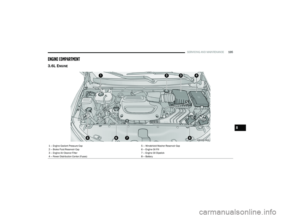
ENGINE COMPARTMENT
3.6L ENGINE
1 — Engine Coolant Pressure Cap 5 — Windshield Washer Reservoir Cap
2 — Brake Fluid Reservoir Cap 6 — Engine Oil Fill
3 — Engine Air Cleaner Filter 7 — Engine Oil Dipstick
4 — Power Distribution Center (Fuses) 8 — Battery
8
23_RUV_OM_EN_US_t.book Page 195