trailer CHRYSLER VOYAGER 2023 Owners Manual
[x] Cancel search | Manufacturer: CHRYSLER, Model Year: 2023, Model line: VOYAGER, Model: CHRYSLER VOYAGER 2023Pages: 256, PDF Size: 13.97 MB
Page 5 of 256
3
GETTING TO KNOW YOUR
INSTRUMENT PANEL
BASE INSTRUMENT CLUSTER ...........................................59Base Instrument Cluster Descriptions....................... 60
PREMIUM INSTRUMENT CLUSTER ...................................61 Premium Instrument Cluster Descriptions ................ 62
INSTRUMENT CLUSTER DISPLAY ....................................62 Instrument Cluster Display Location And Controls ... 62
Oil Life Reset ............................................................... 63
KeySense Cluster Messages —
If Equipped .................................................................. 64
Instrument Cluster Display Menu Items ................... 64
Battery Saver On/Battery Saver Mode Message —
Electrical Load Reduction Actions — If Equipped ..... 66
WARNING LIGHTS AND MESSAGES.................................67 Red Warning Lights ..................................................... 67
Yellow Warning Lights ................................................. 70
Yellow Indicator Lights ................................................ 72
Green Indicator Lights ................................................ 72
White Indicator Lights ................................................. 72
Blue Indicator Lights ................................................... 73
ONBOARD DIAGNOSTIC SYSTEM — OBD II .....................73 Onboard Diagnostic System
(OBD II) Cybersecurity ................................................. 73
EMISSIONS INSPECTION AND MAINTENANCE
PROGRAMS ........................................................................74
STARTING AND OPERATING
STARTING THE ENGINE ...................................................... 75 Normal Starting ........................................................... 75
AutoPark .......................................................................75
Cold Weather Operation
(Below –22°F Or −30°C) ........................................... 77
After Starting — Warming Up The Engine ................... 77
If Engine Fails To Start ............................................... 77
To Turn Off The Engine Using ENGINE START/STOP
Button ........................................................................... 78
ENGINE BLOCK HEATER — IF EQUIPPED ........................ 78
ENGINE BREAK-IN RECOMMENDATIONS ....................... 78
PARKING BRAKE ................................................................ 79 Electric Park Brake (EPB) ........................................... 79
AUTOMATIC TRANSMISSION ............................................ 81 Ignition Park Interlock ................................................. 81
Brake/Transmission Shift Interlock (BTSI) System ... 82
9-Speed Automatic Transmission ..............................82
Gear Ranges ................................................................ 82
ACTIVE NOISE CANCELLATION ......................................... 84
POWER STEERING .............................................................. 84
STOP/START SYSTEM — IF EQUIPPED ............................ 85 Autostop Mode............................................................. 85
Possible Reasons The Engine Does Not Autostop .... 85
To Start The Engine While In Auto Stop/Start ........... 85
To Manually Turn Off The Stop/Start System ............ 86
To Manually Turn On The Stop/Start System ............ 86
System Malfunction..................................................... 86
CRUISE CONTROL SYSTEMS — IF EQUIPPED ................. 86 Cruise Control .............................................................. 86 PARKSENSE REAR PARK ASSIST —
IF EQUIPPED ...................................................................... 87
ParkSense Sensors ..................................................... 88
ParkSense Warning Display........................................ 88
ParkSense Display ...................................................... 88
Enabling And Disabling ParkSense ............................ 91
Service The ParkSense Rear Park Assist System ..... 91
Cleaning The ParkSense System ............................... 91
ParkSense System Usage Precautions ...................... 91
PARKVIEW REAR BACK UP CAMERA ............................. 92
REFUELING THE VEHICLE .................................................. 93
VEHICLE LOADING ............................................................. 93 Certification Label ....................................................... 93
TRAILER TOWING ............................................................... 94 Common Towing Definitions....................................... 94
Trailer Hitch Classification .......................................... 96
Trailer Towing Weights (Maximum Trailer Weight
Ratings) ....................................................................... 97
Vehicle Loading Chart ................................................. 97
Trailer And Tongue Weight ......................................... 99
Towing Requirements ................................................ 99
Towing Tips ............................................................... 101
RECREATIONAL TOWING (BEHIND MOTORHOME) ..... 101 Towing This Vehicle Behind Another Vehicle ........... 101
DRIVING TIPS ....................................................................102 Driving On Slippery Surfaces .................................... 102
Driving Through Water ............................................. 103
23_RUV_OM_EN_US_t.book Page 3
Page 71 of 256
GETTING TO KNOW YOUR INSTRUMENT PANEL69
NOTE:This light may turn on if the accelerator and brake pedals
are pressed at the same time.
If the light continues to flash when the vehicle is running,
immediate service is required and you may experience
reduced performance, an elevated/rough idle, or engine
stall and your vehicle may require towing. The light will
come on when the ignition is placed in the ON/RUN or
ACC/ON/RUN position and remain on briefly as a bulb
check. If the light does not come on during starting, have
the system checked by an authorized dealer.
Engine Coolant Temperature Warning Light
This warning light warns of an overheated
engine condition. If the engine coolant
temperature is too high, this indicator will
illuminate and a single chime will sound. If the
temperature reaches the upper limit, a continuous chime
will sound for four minutes or until the engine is able to
cool; whichever comes first.
If the light turns on while driving, safely pull over and stop
the vehicle. If the Air Conditioning (A/C) system is on, turn
it off. Also, shift the transmission into NEUTRAL (N) and
idle the vehicle. If the temperature reading does not return
to normal, turn the engine off immediately and call for
service
Úpage 187.
Hood Open Warning Light
This warning light will illuminate when the hood
is left open and not fully closed.
NOTE:If the vehicle is moving, there will also be a single chime.
Liftgate Open Warning Light
This warning light will illuminate when the
liftgate is open.
NOTE:If the vehicle is moving, there will also be a single chime.
Oil Temperature Warning Light
This warning light will illuminate to indicate the
engine oil temperature is high. If the light turns
on while driving, stop the vehicle and shut off
the engine as soon as possible. Wait for oil
temperature to return to normal levels.
Oil Pressure Warning Light
This warning light will illuminate to indicate low
engine oil pressure. If the light turns on while
driving, stop the vehicle, shut off the engine as
soon as possible, and contact an authorized
dealer. A chime will sound when this light turns on.
Do not operate the vehicle until the cause is corrected.
This light does not indicate how much oil is in the engine.
The engine oil level must be checked under the hood.
Seat Belt Reminder Warning Light
This warning light indicates when the driver or
passenger seat belt is unbuckled. When the
ignition is first placed in the ON/RUN or
ACC/ON/RUN position and if the driver’s seat
belt is unbuckled, a chime will sound and the light will turn on. When driving, if the driver or front passenger seat belt
remains unbuckled, the Seat Belt Reminder Light will flash
or remain on continuously and a chime will sound
Úpage 134.
Transmission Temperature Warning Light
This warning light will illuminate to warn of a
high transmission fluid temperature. This may
occur with strenuous usage such as trailer
towing. If this light turns on, stop the vehicle
and run the engine at idle or slightly faster, with the
transmission in PARK (P) or NEUTRAL (N), until the light
turns off. Once the light turns off, you may continue to
drive normally.
WARNING!
If you continue operating the vehicle when the Transmission
Temperature Warning Light is illuminated you could cause
the fluid to boil over, come in contact with hot engine or
exhaust components and cause a fire.
CAUTION!
Continuous driving with the Transmission Temperature
Warning Light illuminated will eventually cause severe
transmission damage or transmission failure.
3
23_RUV_OM_EN_US_t.book Page 69
Page 93 of 256
STARTING AND OPERATING91
(Continued)
ENABLING AND DISABLING PARKSENSE
ParkSense can be enabled and disabled with
the ParkSense switch, located on the switch
panel below the Uconnect display.
When the ParkSense switch is pushed to disable the system,
the instrument cluster will display the “PARKSENSE OFF”
message for approximately five seconds. When the gear
selector is moved to REVERSE and the system is disabled, the
instrument cluster display will show the “PARKSENSE OFF”
message for as long as the vehicle is in REVERSE.
The ParkSense switch LED will be on when ParkSense is
disabled or requires service. The ParkSense switch LED will
be off when the system is enabled. If the ParkSense switch
is pushed, and requires service, the ParkSense switch LED
will blink momentarily, and then the LED will be on.
SERVICE THE PARKSENSE REAR PARK
A
SSIST SYSTEM
During vehicle start up, when the ParkSense Rear Park Assist
system has detected a faulted condition, the instrument cluster
will actuate a single chime, once per ignition cycle, and it will
display the “PARKSENSE UNAVAILABLE WIPE REAR SENSORS”
or the “PARKSENSE UNAVAILABLE SERVICE REQUIRED”. When
the gear selector is moved to REVERSE and the system has
detected a faulted condition, the instrument cluster display
Ú
page 62 will show the "PARKSENSE UNAVAILABLE WIPE
REAR SENSORS" or "PARKSENSE UNAVAILABLE SERVICE
REQUIRED" message for five seconds while the vehicle is in
REVERSE. The vehicle graphic will remain displayed for as long
as the vehicle is in REVERSE. If “PARKSENSE UNAVAILABLE WIPE REAR SENSORS” appears
in the instrument cluster display, make sure the outer surface
and the underside of the rear fascia/bumper is clean and clear
of snow, ice, mud, dirt, or other obstructions and then cycle the
ignition. If the message continues to appear, see an authorized
dealer.
If “PARKSENSE UNAVAILABLE SERVICE REQUIRED”
appears in the instrument cluster display, see an
authorized dealer.
CLEANING THE PARKSENSE SYSTEM
Clean the ParkSense sensors with water, car wash soap,
and a soft cloth. Do not use rough or hard cloths. Do not
scratch or poke the sensors.
PARKSENSE SYSTEM USAGE
P
RECAUTIONS
NOTE:
Ensure that the rear fascia/bumper is free of snow, ice,
mud, dirt, and debris to keep the ParkSense system
operating properly.
Jackhammers, large trucks, and other vibrations could
affect the performance of ParkSense.
When you turn ParkSense off, the instrument cluster
will display “PARKSENSE OFF”. Furthermore, once you
turn ParkSense off, it remains off until you turn it on
again, even if you cycle the ignition.
When you move the gear selector to the REVERSE posi -
tion and ParkSense is turned off, the instrument
cluster display will show “PARKSENSE OFF” for as long
as the vehicle is in REVERSE.
ParkSense, when on, will reduce the volume of the
radio when it is sounding a tone.
Clean the ParkSense sensors regularly, taking care not
to scratch or damage them. The sensors must not be
covered with ice, snow, slush, mud, dirt, or debris.
Failure to do so can result in the system not working
properly. The ParkSense system might not detect an
obstacle behind the fascia/bumper, or it could provide
a false indication that an obstacle is behind the
fascia/bumper.
ParkSense should be disabled when the liftgate is in
the open position.
Use the ParkSense switch to turn the ParkSense
system off if objects such as bicycle carriers, trailer
hitches, etc., are placed within 12 inches (30 cm) of
the rear fascia/bumper. Failure to do so can result
in the system misinterpreting a close object as a
blockage or sensor problem, causing the “PARKSENSE
UNAVAILABLE WIPE REAR SENSORS” message to be
displayed in the instrument cluster display.
WARNING!
Drivers must be careful when backing up even when
using ParkSense. Always check carefully behind your
vehicle, look behind you, and be sure to check for
pedestrians, animals, other vehicles, obstructions,
and blind spots before backing up. You are respon -
sible for safety and must continue to pay attention to
your surroundings. Failure to do so can result in
serious injury or death.
4
23_RUV_OM_EN_US_t.book Page 91
Page 96 of 256
94STARTING AND OPERATING
Payload
The payload of a vehicle is defined as the allowable load
weight a truck can carry, including the weight of the driver,
all passengers, options and cargo.
Gross Axle Weight Rating (GAWR)
The GAWR is the maximum permissible load on the front
and rear axles. The load must be distributed in the cargo
area so that the GAWR of each axle is not exceeded.
Each axle GAWR is determined by the components in
the system with the lowest load carrying capacity (axle,
springs, tires or wheels). Heavier axles or suspension
components sometimes specified by purchasers for
increased durability do not necessarily increase the
vehicle's GVWR.
Tire Size
The tire size on the Vehicle Certification Label represents
the actual tire size on your vehicle. Replacement tires
must be equal to the load capacity of this tire size.
Rim Size
This is the rim size that is appropriate for the tire size
listed.
Inflation Pressure
This is the cold tire inflation pressure for your vehicle for
all loading conditions up to full GAWR.
Curb Weight
The curb weight of a vehicle is defined as the total weight
of the vehicle with all fluids, including vehicle fuel, at full
capacity conditions, and with no occupants or cargo
loaded into the vehicle. The front and rear curb weight values are determined by weighing your vehicle on a
commercial scale before any occupants or cargo are
added.
Loading
The actual total weight and the weight of the front and rear
of your vehicle at the ground can best be determined by
weighing it when it is loaded and ready for operation.
The entire vehicle should first be weighed on a commercial
scale to ensure that the GVWR has not been exceeded.
The weight on the front and rear of the vehicle should then
be determined separately to be sure that the load is
properly distributed over the front and rear axle. Weighing
the vehicle may show that the GAWR of either the front or
rear axles has been exceeded but the total load is within
the specified GVWR. If so, weight must be shifted from
front to rear or rear to front as appropriate until the
specified weight limitations are met. Store the heavier
items down low and be sure that the weight is distributed
equally. Stow all loose items securely before driving.
Improper weight distributions can have an adverse effect
on the way your vehicle steers and handles and the way
the brakes operate.
TRAILER TOWING
In this section you will find safety tips and information on
limits to the type of towing you can reasonably do with your
vehicle. Before towing a trailer, carefully review this
information to tow your load as efficiently and safely as
possible.
To maintain the New Vehicle Limited Warranty coverage,
follow the requirements and recommendations in this
manual concerning vehicles used for trailer towing.
COMMON TOWING DEFINITIONS
The following trailer towing related definitions will assist
you in understanding the following information:
Gross Vehicle Weight Rating (GVWR)
GVWR is the total allowable weight of your vehicle. This
includes driver, passengers, cargo and tongue weight.
The total load must be limited so that you do not exceed
the GVWR
Úpage 93.
Gross Trailer Weight (GTW)
GTW is the weight of the trailer plus the weight of all cargo,
consumables and equipment (permanent or temporary)
loaded in or on the trailer in its "loaded and ready for
operation" condition.
The recommended way to measure GTW is to put your fully
loaded trailer on a vehicle scale. The entire weight of the
trailer must be supported by the scale.
WARNING!
Do not load your vehicle any heavier than the GVWR or
the maximum front and rear GAWR. If you do, parts on
your vehicle can break, or it can change the way your
vehicle handles. This could cause you to lose control.
Overloading can shorten the life of your vehicle.
23_RUV_OM_EN_US_t.book Page 94
Page 97 of 256
STARTING AND OPERATING95
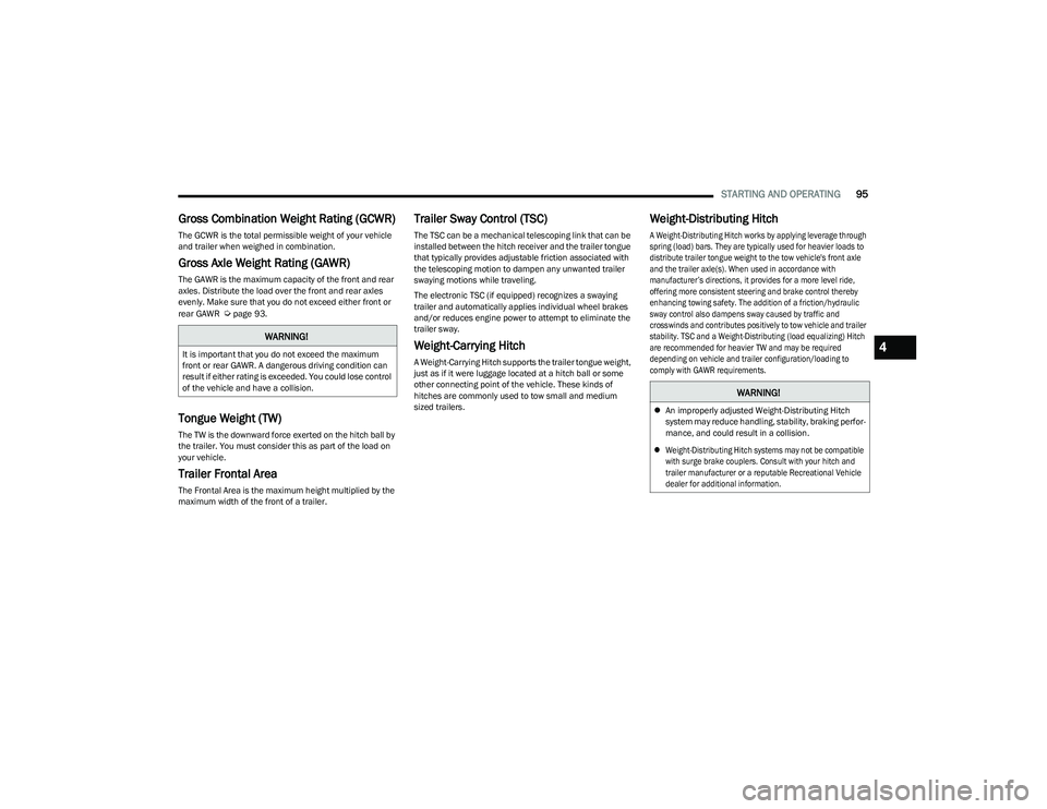
Gross Combination Weight Rating (GCWR)
The GCWR is the total permissible weight of your vehicle
and trailer when weighed in combination.
Gross Axle Weight Rating (GAWR)
The GAWR is the maximum capacity of the front and rear
axles. Distribute the load over the front and rear axles
evenly. Make sure that you do not exceed either front or
rear GAWR
Úpage 93.
Tongue Weight (TW)
The TW is the downward force exerted on the hitch ball by
the trailer. You must consider this as part of the load on
your vehicle.
Trailer Frontal Area
The Frontal Area is the maximum height multiplied by the
maximum width of the front of a trailer.
Trailer Sway Control (TSC)
The TSC can be a mechanical telescoping link that can be
installed between the hitch receiver and the trailer tongue
that typically provides adjustable friction associated with
the telescoping motion to dampen any unwanted trailer
swaying motions while traveling.
The electronic TSC (if equipped) recognizes a swaying
trailer and automatically applies individual wheel brakes
and/or reduces engine power to attempt to eliminate the
trailer sway.
Weight-Carrying Hitch
A Weight-Carrying Hitch supports the trailer tongue weight,
just as if it were luggage located at a hitch ball or some
other connecting point of the vehicle. These kinds of
hitches are commonly used to tow small and medium
sized trailers.
Weight-Distributing Hitch
A Weight-Distributing Hitch works by applying leverage through
spring (load) bars. They are typically used for heavier loads to
distribute trailer tongue weight to the tow vehicle's front axle
and the trailer axle(s). When used in accordance with
manufacturer’s directions, it provides for a more level ride,
offering more consistent steering and brake control thereby
enhancing towing safety. The addition of a friction/hydraulic
sway control also dampens sway caused by traffic and
crosswinds and contributes positively to tow vehicle and trailer
stability. TSC and a Weight-Distributing (load equalizing) Hitch
are recommended for heavier TW and may be required
depending on vehicle and trailer configuration/loading to
comply with GAWR requirements.
WARNING!
It is important that you do not exceed the maximum
front or rear GAWR. A dangerous driving condition can
result if either rating is exceeded. You could lose control
of the vehicle and have a collision.
WARNING!
An improperly adjusted Weight-Distributing Hitch
system may reduce handling, stability, braking perfor -
mance, and could result in a collision.
Weight-Distributing Hitch systems may not be compatible
with surge brake couplers. Consult with your hitch and
trailer manufacturer or a reputable Recreational Vehicle
dealer for additional information.
4
23_RUV_OM_EN_US_t.book Page 95
Page 98 of 256
96STARTING AND OPERATING
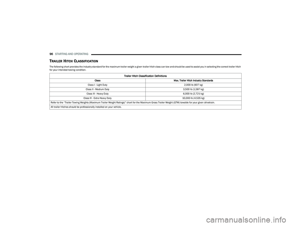
TRAILER HITCH CLASSIFICATION
The following chart provides the industry standard for the maximum trailer weight a given trailer hitch class can tow and should be used to assist you in selecting the correct trailer hitch
for your intended towing condition.
Trailer Hitch Classification Definitions
Class Max. Trailer Hitch Industry Standards
Class I - Light Duty 2,000 lb (907 kg)
Class II - Medium Duty 3,500 lb (1,587 kg)
Class III - Heavy Duty 6,000 lb (2,721 kg)
Class IV - Extra Heavy Duty 10,000 lb (4,535 kg)
Refer to the “Trailer Towing Weights (Maximum Trailer Weight Ratings)” chart for the Maximum Gross Trailer Weight (GTW) towable for your given drivetrain.
All trailer hitches should be professionally installed on your vehicle.
23_RUV_OM_EN_US_t.book Page 96
Page 99 of 256
STARTING AND OPERATING97
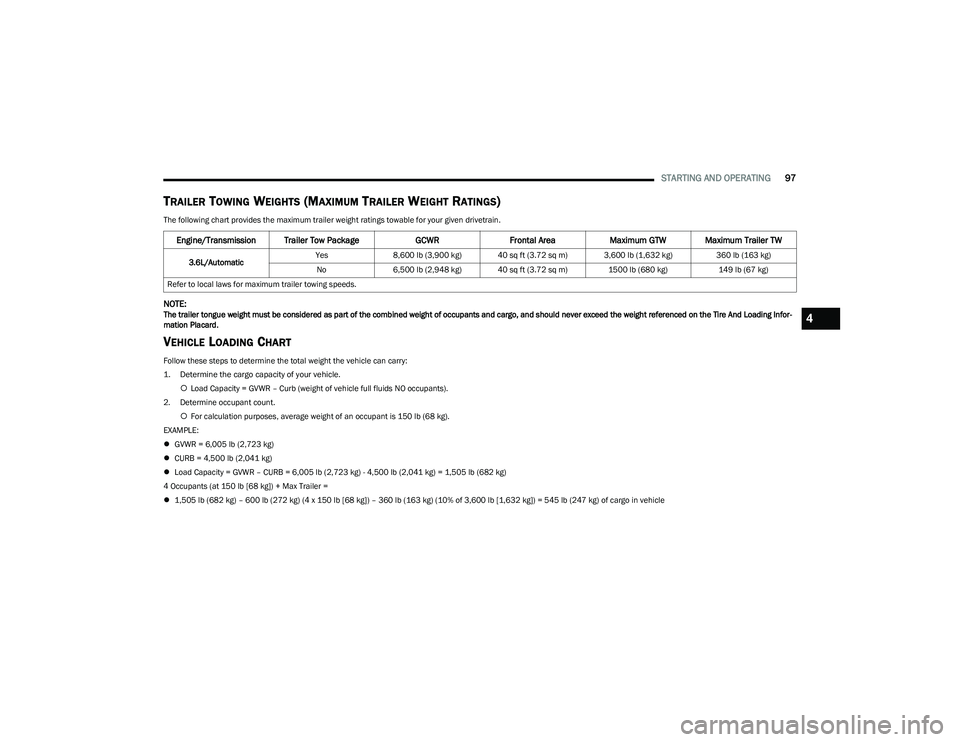
TRAILER TOWING WEIGHTS (MAXIMUM TRAILER WEIGHT RATINGS)
The following chart provides the maximum trailer weight ratings towable for your given drivetrain.
NOTE:The trailer tongue weight must be considered as part of the combined weight of occupants and cargo, and should never exceed the weight referenced on the Tire And Loading Infor -
mation Placard.
VEHICLE LOADING CHART
Follow these steps to determine the total weight the vehicle can carry:
1. Determine the cargo capacity of your vehicle.
Load Capacity = GVWR – Curb (weight of vehicle full fluids NO occupants).
2. Determine occupant count. For calculation purposes, average weight of an occupant is 150 lb (68 kg).
EXAMPLE:
GVWR = 6,005 lb (2,723 kg)
CURB = 4,500 lb (2,041 kg)
Load Capacity = GVWR – CURB = 6,005 lb (2,723 kg) - 4,500 lb (2,041 kg) = 1,505 lb (682 kg)
4 Occupants (at 150 lb [68 kg]) + Max Trailer =
1,505 lb (682 kg) – 600 lb (272 kg) (4 x 150 lb [68 kg]) – 360 lb (163 kg) (10% of 3,600 lb [1,632 kg]) = 545 lb (247 kg) of cargo in vehicle
Engine/Transmission Trailer Tow Package GCWRFrontal Area Maximum GTW Maximum Trailer TW
3.6L/Automatic Yes
8,600 lb (3,900 kg) 40 sq ft (3.72 sq m) 3,600 lb (1,632 kg) 360 lb (163 kg)
No 6,500 lb (2,948 kg) 40 sq ft (3.72 sq m) 1500 lb (680 kg) 149 lb (67 kg)
Refer to local laws for maximum trailer towing speeds.
4
23_RUV_OM_EN_US_t.book Page 97
Page 100 of 256
98STARTING AND OPERATING
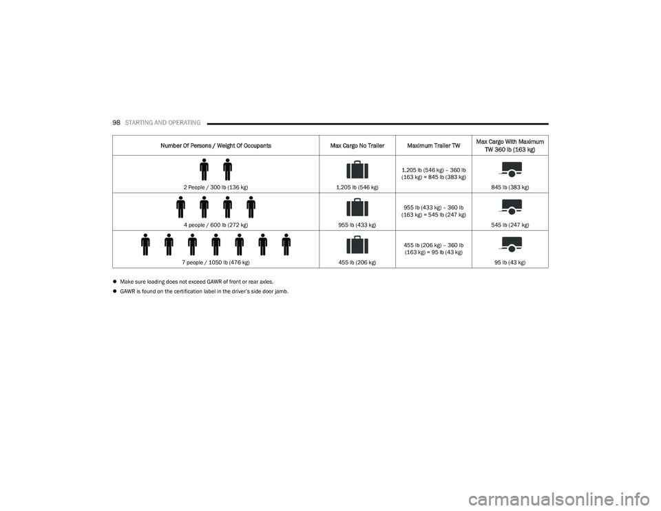
Make sure loading does not exceed GAWR of front or rear axles.
GAWR is found on the certification label in the driver’s side door jamb.
Number Of Persons / Weight Of Occupants Max Cargo No Trailer Maximum Trailer TWMax Cargo With Maximum
TW 360 lb (163 kg)
2 People / 300 lb (136 kg) 1,205 lb (546 kg)1,205 lb (546 kg) – 360 lb
(163 kg) = 845 lb (383 kg)
845 lb (383 kg)
4 people / 600 lb (272 kg) 955 lb (433 kg)955 lb (433 kg) – 360 lb
(163 kg) = 545 lb (247 kg)
545 lb (247 kg)
7 people / 1050 lb (476 kg) 455 lb (206 kg)455 lb (206 kg) – 360 lb
(163 kg) = 95 lb (43 kg)
95 lb (43 kg)
23_RUV_OM_EN_US_t.book Page 98
Page 101 of 256
STARTING AND OPERATING99
(Continued)
TRAILER AND TONGUE WEIGHT
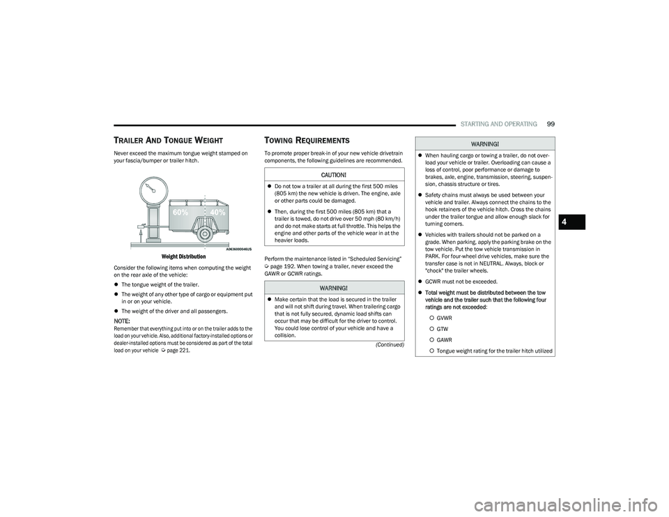
Never exceed the maximum tongue weight stamped on
your fascia/bumper or trailer hitch.
Weight Distribution
Consider the following items when computing the weight
on the rear axle of the vehicle:
The tongue weight of the trailer.
The weight of any other type of cargo or equipment put
in or on your vehicle.
The weight of the driver and all passengers.
NOTE:
Remember that everything put into or on the trailer adds to the
load on your vehicle. Also, additional factory-installed options or
dealer-installed options must be considered as part of the total
load on your vehicle
Ú
page 221.
TOWING REQUIREMENTS
To promote proper break-in of your new vehicle drivetrain
components, the following guidelines are recommended.
Perform the maintenance listed in “Scheduled Servicing”
Úpage 192. When towing a trailer, never exceed the
GAWR or GCWR ratings.
CAUTION!
Do not tow a trailer at all during the first 500 miles
(805 km) the new vehicle is driven. The engine, axle
or other parts could be damaged.
Then, during the first 500 miles (805 km) that a
trailer is towed, do not drive over 50 mph (80 km/h)
and do not make starts at full throttle. This helps the
engine and other parts of the vehicle wear in at the
heavier loads.
WARNING!
Make certain that the load is secured in the trailer
and will not shift during travel. When trailering cargo
that is not fully secured, dynamic load shifts can
occur that may be difficult for the driver to control.
You could lose control of your vehicle and have a
collision.
When hauling cargo or towing a trailer, do not over -
load your vehicle or trailer. Overloading can cause a
loss of control, poor performance or damage to
brakes, axle, engine, transmission, steering, suspen -
sion, chassis structure or tires.
Safety chains must always be used between your
vehicle and trailer. Always connect the chains to the
hook retainers of the vehicle hitch. Cross the chains
under the trailer tongue and allow enough slack for
turning corners.
Vehicles with trailers should not be parked on a
grade. When parking, apply the parking brake on the
tow vehicle. Put the tow vehicle transmission in
PARK. For four-wheel drive vehicles, make sure the
transfer case is not in NEUTRAL. Always, block or
"chock" the trailer wheels.
GCWR must not be exceeded.
Total weight must be distributed between the tow
vehicle and the trailer such that the following four
ratings are not exceeded :
GVWR
GTW
GAWR
Tongue weight rating for the trailer hitch utilized
WARNING!
4
23_RUV_OM_EN_US_t.book Page 99
Page 102 of 256
100STARTING AND OPERATING
Towing Requirements — Tires
Do not attempt to tow a trailer while using a compact
spare tire.
Do not drive more than 50 mph (80 km/h) when towing
while using a full size spare tire.
Proper tire inflation pressures are essential to the safe
and satisfactory operation of your vehicle.
Check the trailer tires for proper tire inflation pressures
before trailer usage.
Check for signs of tire wear or visible tire damage
before towing a trailer.
Replacing tires with a higher load carrying capacity will
not increase the vehicle's GVWR and GAWR limits.
For further information
Úpage 224.
Towing Requirements — Trailer Brakes
Do not interconnect the hydraulic brake system or
vacuum system of your vehicle with that of the trailer.
This could cause inadequate braking and possible
personal injury.
An electronically actuated trailer brake controller is
required when towing a trailer with electronically actu -
ated brakes. When towing a trailer equipped with a
hydraulic surge actuated brake system, an electronic
brake controller is not required.
Trailer brakes are recommended for trailers over
1,000 lb (453 kg) and required for trailers in excess of
2,000 lb (907 kg).
Towing Requirements — Trailer Lights And
Wiring
Whenever you pull a trailer, regardless of the trailer size,
stop lights and turn signals on the trailer are required for
motoring safety.
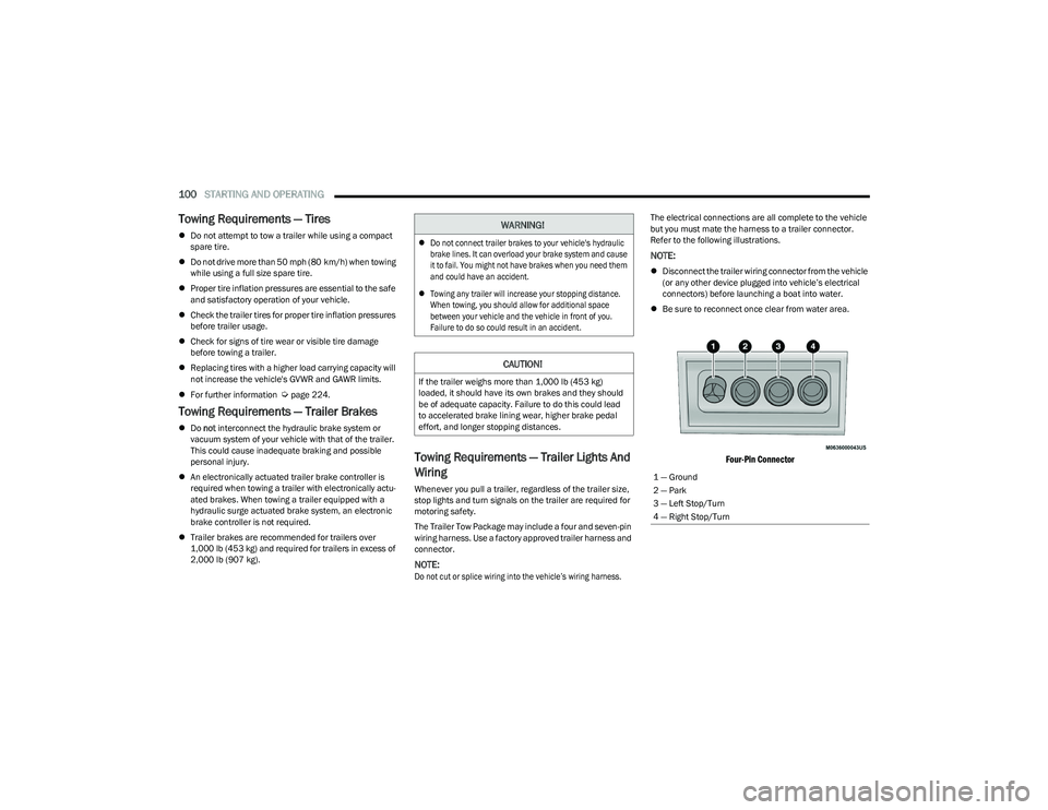
The Trailer Tow Package may include a four and seven-pin
wiring harness. Use a factory approved trailer harness and
connector.
NOTE:
Do not cut or splice wiring into the vehicle’s wiring harness.
The electrical connections are all complete to the vehicle
but you must mate the harness to a trailer connector.
Refer to the following illustrations.
NOTE:
Disconnect the trailer wiring connector from the vehicle
(or any other device plugged into vehicle’s electrical
connectors) before launching a boat into water.
Be sure to reconnect once clear from water area.
Four-Pin Connector
WARNING!
Do not connect trailer brakes to your vehicle's hydraulic
brake lines. It can overload your brake system and cause
it to fail. You might not have brakes when you need them
and could have an accident.
Towing any trailer will increase your stopping distance.
When towing, you should allow for additional space
between your vehicle and the vehicle in front of you.
Failure to do so could result in an accident.
CAUTION!
If the trailer weighs more than 1,000 lb (453 kg)
loaded, it should have its own brakes and they should
be of adequate capacity. Failure to do this could lead
to accelerated brake lining wear, higher brake pedal
effort, and longer stopping distances.
1 — Ground
2 — Park
3 — Left Stop/Turn
4 — Right Stop/Turn
23_RUV_OM_EN_US_t.book Page 100