ignition CITROEN AMI 2022 Owners Manual
[x] Cancel search | Manufacturer: CITROEN, Model Year: 2022, Model line: AMI, Model: CITROEN AMI 2022Pages: 44, PDF Size: 1.45 MB
Page 5 of 44
3
Overview
Safety precautions -
Electric vehicles
An electric vehicle has two types of electrical
circuit:
–
vehicle traction provided by a 48 V battery
module.
–
power supply for the on-board circuit
(instrument panel, lights, ventilation/heating,
USB socket, etc.), provided by a 12
V battery
.
Precautions relating to the 48 V electrical
circuit
The components and cables which make
up the traction electrical circuit are
marked with this symbol.
The electric vehicle's charging system may become hot during use and after the
ignition is switched off.
All work on or modifications to the vehicle’s
electrical system (traction battery, cables and
other components visible from the interior or
exterior) is strictly prohibited - risk of severe
burns or electric shock (short-circuit)!
If required, call a dealer or qualified
workshop.
Precautions relating to the electrical
installation
Before any connection is made, check
that the electrical installation to be used
complies with applicable standards and is
compatible with the vehicle.
In case of doubt, contact a professional
installer.
Precautions related to vehicle cleaning
Before cleaning the vehicle, check that
the windows and doors are properly
closed.
Do not wash the vehicle while the traction
battery is being charged.
Precautions in the event of a breakdown
In the event of a complete loss of power, the
vehicle is no longer driven by the electric motor.
Quickly move the vehicle to a safe place in
accordance with all roadside safety regulations.
Immobilise the vehicle, activate the hazard
warning lamps, put on the high visibility safety
vest, leave the vehicle and find a safe place.
Call a dealer or qualified workshop as soon as
possible.
Precautions related to road accidents
In the event of an accident or impact
to the vehicle's underbody
In situations like these, the electrical circuit or
traction battery may be seriously damaged.
Stop as soon as it is safe to do so.
Apply the parking brake and switch off the
ignition.
Call a dealer or qualified workshop as soon
as possible.
In the event of exposure to a fire
Immediately exit and evacuate all
passengers from the vehicle. Never attempt
to fight the fire yourself - risk of explosion!
You must immediately contact the emergency
services, informing them that the incident
involves an electric vehicle.
Overview
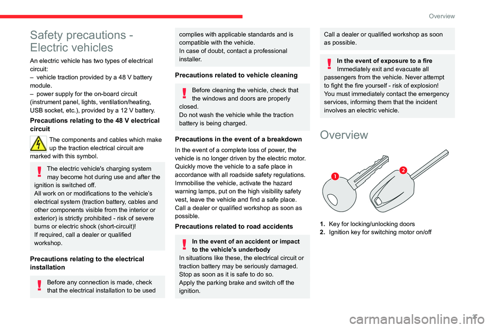
1. Key for locking/unlocking doors
2. Ignition key for switching motor on/off
Page 8 of 44
6
Dashboard instruments
Instrument panel with
monochrome display
screen
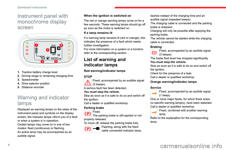
1.Traction battery charge level
2. Driving range or remaining charging time
3. Speedometer
4. Drive selector position
5. Distance recorder
Warning and indicator
lamps
Displayed as warning lamps on the sides of the
instrument panel and symbols on the display
screen, the indicator lamps inform you of a fault
or when a system is in operation.
Certain lamps may come on in one of two
modes: fixed (continuous) or flashing.
An active lamp may be accompanied by an
audible signal.
When the ignition is switched on
The red or orange warning lamps come on for a
few seconds. These warning lamps should go off
as soon as the motor is switched on.
If a lamp remains lit
If a warning lamp remains lit (red or orange), this
indicates the presence of a fault which needs
further investigation.
For more information on a system or a function,
refer to the corresponding section.
List of warning and
indicator lamps
Red warning/indicator lamps
STOP
Fixed, accompanied by an audible signal
(3 beeps).
A serious fault has been detected.
You must stop the vehicle.
Stop as soon as it is safe to do so and switch off
the ignition.
Call a dealer or qualified workshop.
Parking brakeFixed.
The parking brake is still applied or not
properly released.
To move off, release the parking brake fully.
Flashing, along with the fixed
cable connected indicator lamp, dashes instead of the charging time and an
audible signal (repeated beeps).
The charging cable is connected and the parking
brake is released.
Charging will only be possible after applying the
parking brake.
The vehicle cannot be started while the charging
cable is connected.
BrakingFixed, accompanied by an audible signal
(3 beeps).
The brake fluid level has dropped significantly.
You must stop the vehicle.
Stop as soon as it is safe to do so and switch off
the ignition.
Check for the presence of a leak.
Call a dealer or qualified workshop.
Orange warning/indicator lamps
Service
Fixed, accompanied by an audible signal
(1 beep).
One or more major faults, for which there is/are
no specific warning lamp(s), have been detected.
Call a dealer or qualified workshop.
Fixed, combined with another warning
lamp.
Refer to the explanation for the corresponding
lamp.
Page 9 of 44
7
Dashboard instruments
1Minimum traction battery charge levelFixed, combined with the last bar on the
charge meter showing and an audible
signal (1 beep).
The traction battery has reached the first alert
threshold.
Put the vehicle on charge as soon as possible.
Fixed, combined with the flashing
vehicle driving range warning lamp
and an audible signal (1 beep).
The traction battery has reached the second
alert threshold.
The motor's power decreases rapidly.
You must put the vehicle on charge.
Limited powerFixed, accompanied by an audible signal
(1 beep).
A drop in performance in the drive train due to a
low battery temperature.
The decrease in motor power temporarily affects
the vehicle's performance.
Maximum traction battery temperature
Fixed, combined with the STOP
warning lamp and an audible
signal (1 beep).
The traction battery's temperature is too high.
You must stop the vehicle.
Stop as soon as it is safe to do so and switch off
the ignition.
Call a dealer or qualified workshop.
Green warning/indicator lamps
Direction indicators
Flashing left or right indicator with audible
signal.
The left or right direction indicator lamps are on.
Flashing left and right indicators with
audible signal.
The hazard warning lamps are on.
White indicator lamps
Foot on the brake
Flashing.
Insufficient pressure or no pressure
detected on the brake pedal for changing the
direction of travel.
Depress the brake pedal to select or change the
direction of travel.
Vehicle ready to driveFixed.
The vehicle is switched on.
The warning lamp remains on while driving.
The lamp will go out when you switch off the
motor and exit the vehicle.
Fixed, accompanied by an audible signal
(1 beep).
A drive position is selected without any pressure
on the pedals for 5 seconds.
Press D or R on the drive selector, then
accelerate or brake.
Vehicle driving rangeFixed.
The remaining driving range is displayed.
Cable connectedFixed, combined with the remaining
charging time.
The charging cable is connected to the charging
socket.
The traction battery is being charged.
Charge level
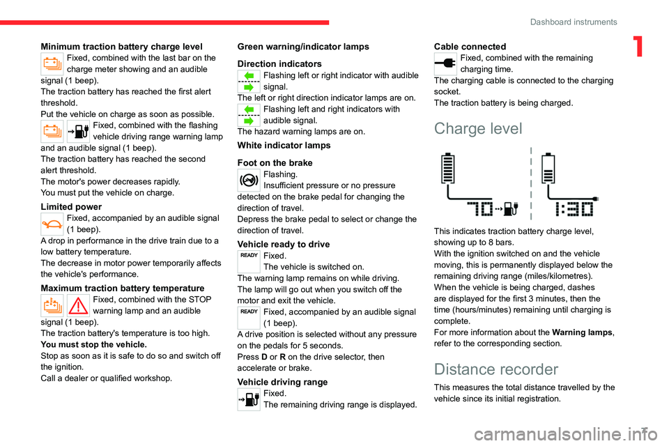
This indicates traction battery charge level,
showing up to 8 bars.
With the ignition switched on and the vehicle
moving, this is permanently displayed below the
remaining driving range (miles/kilometres).
When the vehicle is being charged, dashes
are displayed for the first 3 minutes, then the
time (hours/minutes) remaining until charging is
complete.
For more information about the Warning lamps,
refer to the corresponding section.
Distance recorder
This measures the total distance travelled by the
vehicle since its initial registration.
Page 10 of 44

8
Dashboard instruments
The distance recorder is permanently displayed
when the ignition is switched on and the vehicle
is being charged.
Page 15 of 44

13
Lighting and visibility
4Exterior lighting
When the ignition is switched on, all the lights
come on (sidelamps, dipped beam headlamps
and number plate lamps).
When the ignition is switched off, all the lights
go out.
In some weather conditions (e.g. low
temperature or humidity), misting on the
internal surface of the glass of the headlamps
and rear lamps is normal, and will disappear
after the lamps have been on for a few
minutes.
Never look too closely at the light beam
of LED lamps/headlamps: risk of serious
eye injury!
Direction indicators
► Left or right: lower or raise the multifunction
control stalk beyond the point of resistance.
Three flashes
► Press briefly upwards or downwards (without
going beyond the point of resistance) and the
direction indicators will flash 3 times.
Wipers/Screenwash
Wipers
► Turn the knob to the desired position:Continuous wipe
Intermittent wipe
Switching off
Before operating the wipers in wintry
conditions, clear any snow, ice or frost
from the windscreen, and from around the
wiper arms and blades.
Never operate the wipers when the
windscreen is dry. Before operating the
wipers when the weather is extremely cold or
hot, check that the wiper blades are not stuck
to the windscreen.
Screenwash
► Pull the wiper control stalk towards you and
hold.
The screenwash operates as long as you hold
the multifunction control stalk, followed by a
cycle of 5 wipes when you release the stalk.
To avoid damaging the wiper blades, do not operate the screenwash if the
screenwash reservoir is empty.
Only operate the screenwash if there is no
risk of the fluid freezing on the windscreen
and hindering visibility. In winter, use "very
cold climate" rated products.
Never top up with water.
To ensure flat-bladed wipers remain effective:
–
Handle them with care.
– Clean them regularly using soapy water.
– Do not use them to hold a piece of
cardboard against the windscreen.
Page 17 of 44
15
Safety
5Safety - General
recommendations
Do not remove the labels attached in
different places on your vehicle. They
include safety warnings as well as
identification information for the vehicle.
For any work on your vehicle, use a
qualified workshop that has the technical
information, skills and equipment required, all
of which a dealer or qualified workshop is
able to provide.
Depending on national regulations,
certain safety equipment may be
mandatory: high visibility safety vests,
warning triangles, breathalysers, spare bulbs,
spare fuses, fire extinguisher, first aid kit, etc.
Installing equipment and accessories
Fitting electrical equipment or
accessories not approved by the
Manufacturer may cause excessive power
consumption and faults in your vehicle's
electrical system. Contact a dealer or
qualified workshop for information on the
range of approved accessories.
Any modification or adaptation not intended or
authorised by the Manufacturer or carried out
without meeting the technical requirements
defined by the Manufacturer will result in the
suspension of the commercial warranty.
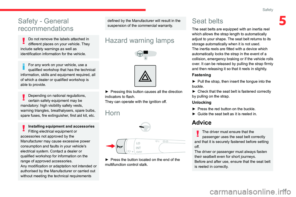
Hazard warning lamps
► Pressing this button causes all the direction
indicators to flash.
They can operate with the ignition off.
Horn
► Press the button located on the end of the
multifunction control stalk.
Seat belts
The seat belts are equipped with an inertia reel
which allows the strap length to automatically
adjust to your shape. The seat belt returns to its
storage automatically when it is not used.
The inertia reels are fitted with a device which
automatically locks the strap in the event of a
collision, emergency braking or if the vehicle rolls
over. It can be released by pulling the strap firmly
and then releasing it so that it reels in slightly.
Fastening
► Pull the strap, then insert the tongue into the
buckle.
►
Check that the seat belt is fastened correctly
by pulling on the strap.
Unlocking
► Press the red button on the buckle.
► Guide the seat belt as it is reeled in.
Advice
The driver must ensure that the passenger uses the seat belt correctly
and that it is securely fastened before setting
off.
The driver or passenger must always fasten
their seatbelt even for short journeys.
Before and after use, ensure that the seat belt
is reeled in correctly.
Page 21 of 44

19
Driving
6When parking on a slope, turn the
wheels against the kerb and/or place a
chock behind one of the wheels, apply the
parking brake and switch off the ignition.
Drive selector
The drive selector has 3 buttons:
D. Forward (Drive)
N. Neutral
R. Reverse (Rear)
When the ignition is switched on, the instrument
panel lights up.
When the motor is switched on, N mode is
displayed on the instrument panel, along with the
READY warning lamp.
►
To move to
D or R mode, depress the brake
pedal and then press the desired button.
By default, this lamp flashes.
Do not depress the accelerator pedal
when switching to D or R mode.
Engine braking and energy recovery
The vehicle is fitted with an energy
recovery system which operates during
deceleration: regenerative braking.
This system of engine braking consists of
recovering part of the energy generated
during deceleration and feeding it back to
the traction battery in order to improve the
vehicle's driving range.
When the traction battery is fully charged
and during the first few miles/kilometres of
a journey, the regenerative braking does not
operate.
Adapt your driving style and use the brake
pedal.
Engine braking and brake pedal
The engine braking can never replace
the brake pedal.
When driving downhill, it is essential not to
exceed the maximum speed of the vehicle
and to voluntarily limit its speed by using the
brake pedal.
In order to protect the drive chain, a
slight decrease in performance may be
observed at low temperatures or during
prolonged use of maximum power.
Starting/Stopping the
vehicle
Ignition switch
1. Stop position Switching off the engine.
2. Ignition on position
Use electrical accessories.
3. Starting position Engine starting.
Starting
When the ignition is switched on, the instrument
panel lights up, all lights come on and the
steering column is unlocked.
Page 22 of 44
20
Driving
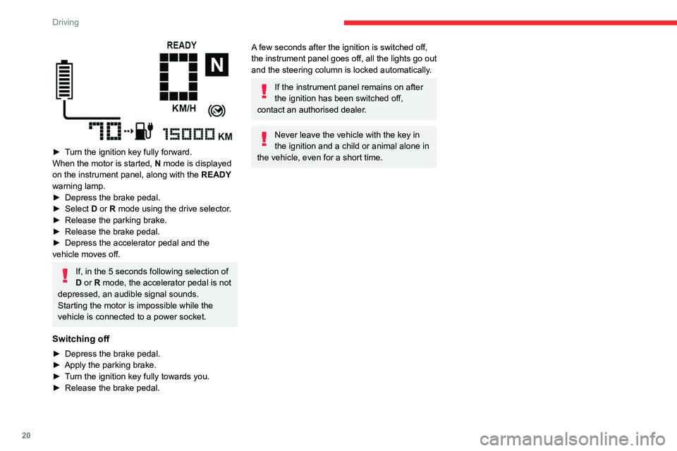
► Turn the ignition key fully forward.
When the motor is started, N mode is displayed
on the instrument panel, along with the READY
warning lamp.
►
Depress the brake pedal.
► Select D
or R mode using the drive selector.
►
Release the parking brake.
► Release the brake pedal.
► Depress the accelerator pedal and the
vehicle moves off.
If, in the 5 seconds following selection of
D or R mode, the accelerator pedal is not
depressed, an audible signal sounds.
Starting the motor is impossible while the
vehicle is connected to a power socket.
Switching off
► Depress the brake pedal.
► Apply the parking brake.
► Turn the ignition key fully towards you.
► Release the brake pedal.
A few seconds after the ignition is switched off,
the instrument panel goes off, all the lights go out
and the steering column is locked automatically.
If the instrument panel remains on after
the ignition has been switched off,
contact an authorised dealer.
Never leave the vehicle with the key in
the ignition and a child or animal alone in
the vehicle, even for a short time.
Page 24 of 44
22
Practical information
Important recommendations
Power socket
Have a professional check that the
electrical system to be used complies with
applicable standards and is compatible with
the vehicle.
Always use a correctly earthed power socket,
protected by a 30
mA
residual current device.
Always use a power socket that is protected
by a circuit-breaker appropriate for the
electrical circuit’s current rating.
Charging cable
Incorrect use of this charging cable may
result in fire, property damage and serious
injury or death by electrocution!
Never use the charging cable if it is defective
or damaged in any way (corrosion, cuts).
Never attempt to repair or open the charging
cable.
If the charging cable is defective, consult
a dealer or qualified workshop to obtain a
replacement.
Never use the charging cable with an
extension cable, a multi-plug socket, a
conversion adaptor or in a damaged power
socket.
Never immerse the charging cable in water.
Never attempt to move the vehicle using the
charging cable.
Plugging in/Unplugging
Never plug the cable into the wall socket
(or unplug it) with wet hands.
Immediately stop charging if the charging
cable or wall socket become too hot to touch.
Do not expose it to flammable vapours - Risk
of electrical arcing or sparks!
After connecting the charging cable, check
that the instrument panel switches on,
otherwise disconnect and reconnect the
charging cable.
Charging will not start if the parking brake is
not applied.
Connection
► Park the vehicle as close as possible to a
power socket.
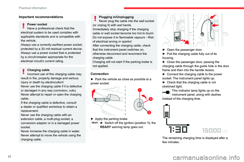
► Apply the parking brake.► Switch off the ignition (position 1); the
READY warning lamp goes out.
► Open the passenger door.
► Pull the charging cable fully out of its
housing.
►
Close the passenger door, passing the
charging
cable through the guide hole in the door
frame and then into the handle recess.
►
Connect the charging cable to the power
socket. The instrument panel lights up.
►
Check that the charging cable is not
stretched tight.
This indicator lamp lights up on the instrument panel, along with dashes
instead of the charging time.
The remaining charging time is displayed after a
few minutes.
Page 25 of 44

23
Practical information
7The charge level increases slowly as charging
progresses.
When the charge is completed, the instrument
panel switches off.
Disconnection
► Disconnect the charging cable from the
power socket.
►
Open the passenger door.
► Store all of the charging cable inside its
housing.
►
Close the passenger door.
Electric motor
1. Screenwash fluid reservoir
2. Fuse box
3. 12
V battery
4. T
raction battery/48
V electrical circuit
5. Electric motor
6. Brake fluid reservoir
Checking levels
Check all of the following levels regularly in
accordance with the Manufacturer's service
schedule. Top them up if required, unless
otherwise indicated.
If a particular level has dropped significantly,
have the corresponding circuit checked by a
dealer or qualified workshop.
Fluids must comply with the
Manufacturer's recommendations.
Used products
Avoid prolonged contact of used fluids
with the skin.
Most of these fluids are harmful to health and
very corrosive.
Do not discard used fluids into sewers
or onto the ground.
Drain used fluids into the dedicated
containers provided by dealers or qualified
workshops.
Brake fluid
Before doing any work
Switch off the ignition, apply the parking
brake, check that the instrument panel is off
and that the charging cable is not connected.
To find out how often the brake fluid should be
replaced, refer to the Manufacturer's servicing
schedule.
Removing front bumper
► Remove the 2 lower fixing screws from the
frame.
►
Remove the 2 upper access flaps from the
wings, pass an arm under the wing and lift it up.
►
Remove the 2 upper side fixing screws from
the flaps.
►
Remove the 2 lower side fixing screws from
the wheel arches.
►
Pull the bumper horizontally for about ten
centimetres until the attachment points come
away.
►
Disconnect the indicator wiring looms.
Before topping up, it is necessary to
protect the motor and its connectors in