Steering rack Citroen BERLINGO 2005 1.G User Guide
[x] Cancel search | Manufacturer: CITROEN, Model Year: 2005, Model line: BERLINGO, Model: Citroen BERLINGO 2005 1.GPages: 462, PDF Size: 10.48 MB
Page 384 of 462
Downloaded from www.Manualslib.com manuals search engine 378
AXLES
SUSPENSION
STEERING
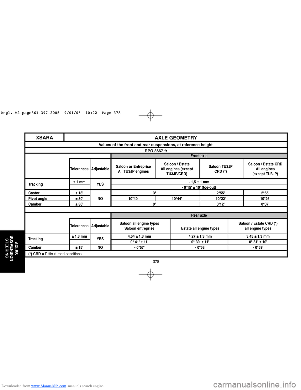
AXLE GEOMETRY XSARA
Values of the front and rear suspensions, at reference height
RPO 8667 #Front axle
Saloon / Estate
Saloon or Entreprise
All engines (exceptSaloon TU3JPSaloon / Estate CRD
Tolerances Adjustable
All TU3JP engines
TU3JP/CRD)CRD (*)All engines
(except TU3JP)
Tracking±1 mm
YES- 1,5 ± 1 mm
- 0°15' ± 10' (toe-out)
Castor ± 18' 3° 2°55' 2°55'
Pivot angle ± 30' NO 10°40' 10°44' 10°22' 10°26'
Camber ± 30' 0° 0°12' 0°07'
Rear axle
Saloon / Estate CRD (*)
Tolerances AdjustableSaloon all engine types
Estate all engine types all engine types Saloon entreprise
Tracking± 1,3 mm
YES4,54 ± 1,3 mm 4,27 ± 1,3 mm 3,45 ± 1,3 mm
0° 41' ± 11' 0° 39' ± 11' 0° 31' ± 10'
Camber ± 15' NO - 0°57' - 0°58' - 0°59'
(*) CRD = Difficult road conditions.
Angl.-t2-page361-397-2005 9/01/06 10:22 Page 378
Page 385 of 462
Downloaded from www.Manualslib.com manuals search engine 379
AXLES
SUSPENSION
STEERING
XSARA
AXLE GEOMETRY
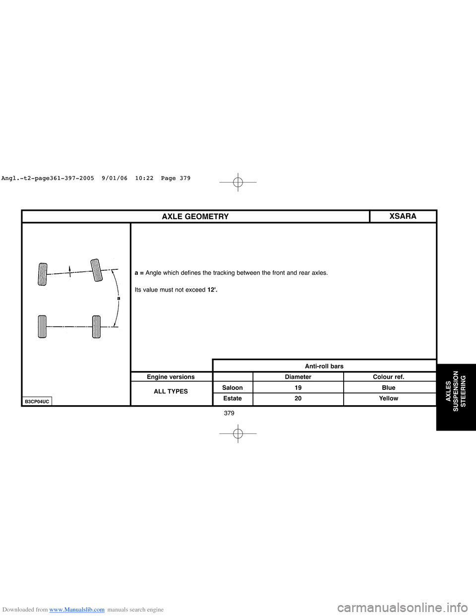
a = Angle which defines the tracking between the front and rear axles.
Its value must not exceed12'.
Anti-roll bars
Engine versions Diameter Colour ref.
ALL TYPESSaloon 19 Blue
Estate 20 Yellow
B3CP04UC
Angl.-t2-page361-397-2005 9/01/06 10:22 Page 379
Page 390 of 462

Downloaded from www.Manualslib.com manuals search engine 384
AXLES
SUSPENSION
STEERING
XSARATIGHTENING TORQUES: MANUAL STEERING
Manual steering
Tightening torques (m.daN).
(7)Pivot ball-joint nut: 4
(8)Link rod lock nut :4.5
(9) Ball-joint on steering rack: 6
(10)Fixing on cradle : 5
(11)Plunger flange screws : 1.2
B3EP042D
Angl.-t2-page361-397-2005 9/01/06 10:22 Page 384
Page 392 of 462

Downloaded from www.Manualslib.com manuals search engine 386
AXLES
SUSPENSION
STEERING
TIGHTENING TORQUES: POWER-ASSISTED STEERING
Power steering
XSARA
Tightening torques (m.daN).
(7)Pivot ball-joint nut: 4
(8)Link rod lock nut: 4.5
(9)Ball-joint on steering rack: 6
(10)Fixing on subframe: 5
(11) Hydraulic pipe connection: 2.5
(12)Valve to housing fixing: 1.2
(13)Plunger flange screw: 1.2
(14) Screw fixing the steering ram
to the housing: 5.5
(15)Nut fixing the steering ram
to the yoke: 5.5
B3EP08RD
Angl.-t2-page361-397-2005 9/01/06 10:22 Page 386
Page 394 of 462
Downloaded from www.Manualslib.com manuals search engine 388
AXLES
SUSPENSION
STEERING
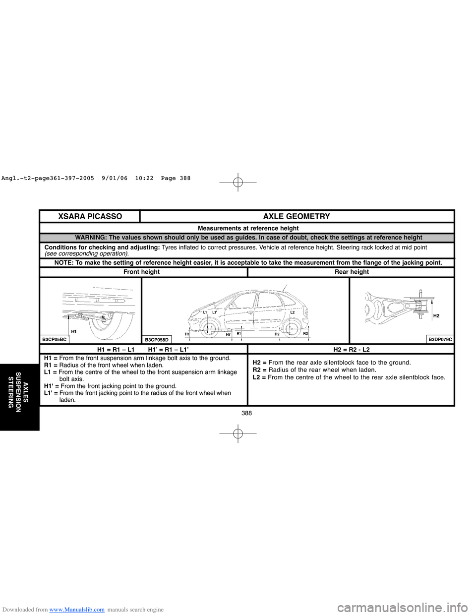
H1 = R1 – L1 H1’ = R1 – L1’
H1 = From the front suspension arm linkage bolt axis to the ground.
R1 =Radius of the front wheel when laden.
L1 =From the centre of the wheel to the front suspension arm linkage
bolt axis.
H1' =From the front jacking point to the ground.
L1' =From the front jacking point to the radius of the front wheel when
laden.H2 = R2 - L2
H2 = From the rear axle silentblock face to the ground.
R2 =Radius of the rear wheel when laden.
L2 =From the centre of the wheel to the rear axle silentblock face.
AXLE GEOMETRY
Measurements at reference height
NOTE: To make the setting of reference height easier, it is acceptable to take the measurement from the flange of the jacking point.
WARNING: The values shown should only be used as guides. In case of doubt, check the settings at reference height
Rear heightFront height
B3CP05BCB3CP058DB3DP079C
XSARA PICASSO
Conditions for checking and adjusting: Tyres inflated to correct pressures. Vehicle at reference height. Steering rack locked at mid point(see corresponding operation).
Angl.-t2-page361-397-2005 9/01/06 10:22 Page 388
Page 396 of 462
Downloaded from www.Manualslib.com manuals search engine 390
AXLES
SUSPENSION
STEERING
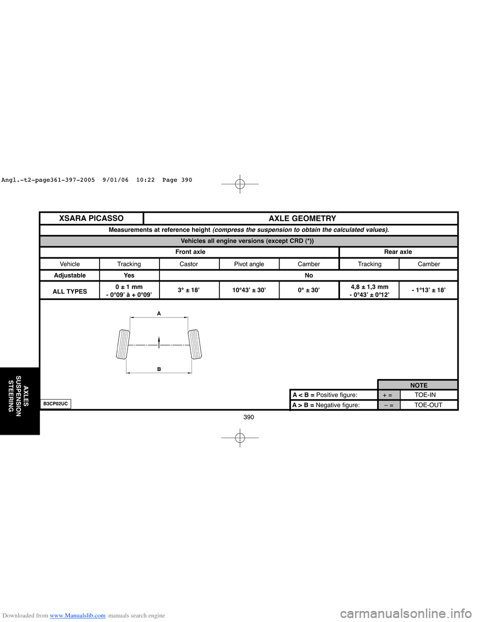
A> B =Negative figure: – = TOE-OUT A < B = Positive figure: + = TOE-INNOTE
AXLE GEOMETRY
Measurements at reference height (compress the suspension to obtain the calculated values).
Vehicles all engine versions (except CRD (*))
Front axle Rear axle
Vehicle Tracking CastorPivot angleCamber Tracking Camber
Adjustable Yes No
ALL TYPES0 ± 1 mm4,8 ± 1,3 mm
- 0°09’ à + 0°09’3° ± 18’ 10°43’ ± 30’ 0° ± 30’
- 0°43’ ± 0°12’- 1°13’ ± 18’
XSARA PICASSO
B3CP02UC
Angl.-t2-page361-397-2005 9/01/06 10:22 Page 390
Page 398 of 462

Downloaded from www.Manualslib.com manuals search engine 392
AXLES
SUSPENSION
STEERING
A> B =Negative figure: – = TOE-OUT A < B = Positive figure: + = TOE-INNOTE
AXLE GEOMETRY
Measurements at reference height (compress the suspension to obtain the calculated values).
Vehicles all engine versions (except CRD (*))
Front axle Rear axle
Vehicle Tracking CastorPivot angleCamber Tracking Camber
Adjustable Yes No
ALL TYPES- 1 ± 1 mm3,7 ± 1,3 mm
- 0°18’ à 0°0’2°56’ ± 18’ 10°25’ ± 30’ 0°07’ ± 30’
- 0°33’ ± 0°12’- 1°14’ ± 18’
XSARA PICASSO
B3CP02UC
Angl.-t2-page361-397-2005 9/01/06 10:22 Page 392
Page 402 of 462
Downloaded from www.Manualslib.com manuals search engine 396
AXLES
SUSPENSION
STEERING
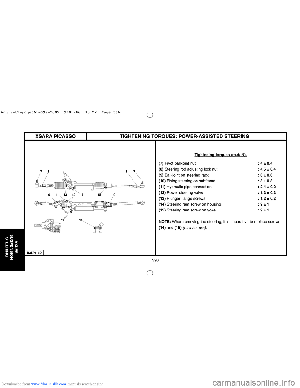
TIGHTENING TORQUES: POWER-ASSISTED STEERING
Tightening torques (m.daN).
(7) Pivot ball-joint nut: 4 ± 0.4
(8) Steering rod adjusting lock nut: 4.5 ± 0.4
(9)Ball-joint on steering rack: 6 ± 0.6
(10) Fixing steering on subframe: 8 ± 0.8
(11)Hydraulic pipe connection: 2.4 ± 0.2
(12)Power steering valve: 1.2 ± 0.2
(13)Plunger flange screws: 1.2 ± 0.2
(14)Steering ram screw on housing: 9 ± 1
(15) Steering ram screw on yoke: 9 ± 1
NOTE:When removing the steering, it is imperative to replace screws
(14)and (15)
(new screws).
B3EP117D
XSARA PICASSO
Angl.-t2-page361-397-2005 9/01/06 10:22 Page 396