headlamp Citroen BERLINGO FIRST 2012 1.G User Guide
[x] Cancel search | Manufacturer: CITROEN, Model Year: 2012, Model line: BERLINGO FIRST, Model: Citroen BERLINGO FIRST 2012 1.GPages: 128, PDF Size: 3.68 MB
Page 77 of 128

75 PRACTICAL INFORMATION
-
1.
Power steering reservoir.
2.
Windscreen/headlamp wash
reservoir.
3.
Coolant reservoir.
4.
Brake fl uid reservoir.
5.
Battery.
6.
Air fi lter.
7.
Dipstick.
8.
Engine oil reservoir.
9.
Priming pump.
1.6 LITRE TURBO DIESEL HDI ENGINE
Page 79 of 128

77 PRACTICAL INFORMATION
-
CHECKING LEVELS
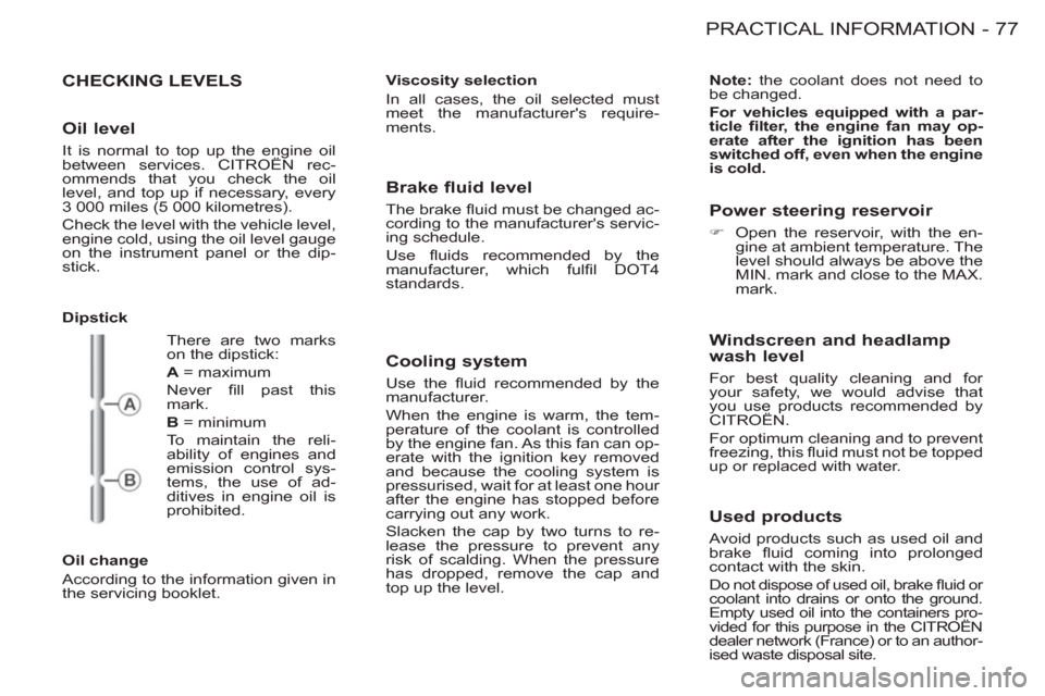
Dipstick
Oil change
According to the information given in
the servicing booklet.
Viscosity selection
In all cases, the oil selected must
meet the manufacturer's require-
ments.
Note:
the coolant does not need to
be changed.
For vehicles equipped with a par-
ticle fi lter, the engine fan may op-
erate after the ignition has been
switched off, even when the engine
is cold.
There are two marks
on the dipstick:
A
= maximum
Never fi ll past this
mark.
B
= minimum
To maintain the reli-
ability of engines and
emission control sys-
tems, the use of ad-
ditives in engine oil is
prohibited.
Brake fluid level
The brake fl uid must be changed ac-
cording to the manufacturer's servic-
ing schedule.
Use fl uids recommended by the
manufacturer, which fulfi l DOT4
standards.
Cooling system
Use the fl uid recommended by the
manufacturer.
When the engine is warm, the tem-
perature of the coolant is controlled
by the engine fan. As this fan can op-
erate with the ignition key removed
and because the cooling system is
pressurised, wait for at least one hour
after the engine has stopped before
carrying out any work.
Slacken the cap by two turns to re-
lease the pressure to prevent any
risk of scalding. When the pressure
has dropped, remove the cap and
top up the level.
Power steering reservoir
�)
Open the reservoir, with the en-
gine at ambient temperature. The
level should always be above the
MIN. mark and close to the MAX.
mark.
Windscreen and headlamp
wash level
For best quality cleaning and for
your safety, we would advise that
you use products recommended by
CITROËN.
For optimum cleaning and to prevent
freezing, this fl uid must not be topped
up or replaced with water.
Used products
Avoid products such as used oil and
brake fl uid coming into prolonged
contact with the skin.
Do not dispose of used oil, brake fl uid or
coolant into drains or onto the ground.
Empty used oil into the containers pro-
vided for this purpose in the CITROËN
dealer network (France) or to an author-
ised waste disposal site.
Oil level
It is normal to top up the engine oil
between services. CITROËN rec-
ommends that you check the oil
level, and top up if necessary, every
3 000 miles (5 000 kilometres).
Check the level with the vehicle level,
engine cold, using the oil level gauge
on the instrument panel or the dip-
stick.
Page 84 of 128

PRACTICAL INFORMATION
82 -
CHANGING A BULB
Front lamps
To replace a dipped/main beam
headlamp or sidelamp bulb:
Remove the grille
- Remove the screw ( 1
).
- Unclip the lug ( A
) of carrier ( 2
) on
each side.
- Remove the grille ( 3
).
Partially remove the wheelarch liner
- Remove the screws ( 1
),
- Remove the screw ( 2
),
- Remove the plastic pins ( 3
).
Page 85 of 128

83 PRACTICAL INFORMATION
-
Partially remove the bumper
- Remove the screws ( 1
),
- Remove the screws ( 2
),
- Pull lightly on the side of the
bumper ( 3
),
- Push in the direction of the ar-
row ( B
), on the latch ( A
), via the
opening ( C
),
- Maintain a light sideways pull on
the bumper,
- Push the bumper sharply for-
wards to release the clips at ( D
).
Remove the headlamp
- Remove the screws ( 1
),
- Unclip the index pin on the head-
lamp ( A
),
- Disconnect the connector ( B
) on
the back of the headlamp,
- Remove the headlamp ( 2
).
Page 86 of 128

PRACTICAL INFORMATION
84 -
Dipped/Main beam headlamps
(H4-60/55W)
After following the procedure for re-
moval of the headlamp:
- Turn and remove the protector ( 6
),
- Disconnect the connector ( C
),
- Unclip the spring ( D
),
- Remove and replace the
bulb ( 3
).
Page 87 of 128

85 PRACTICAL INFORMATION
-
Sidelamps (W 5 W)
After following the procedure for re-
moval of the headlamp:
- Turn and remove the protec-
tor ( 6
).
- Unclip the the bulb holder ( E
).
- Disconnect the connector ( F
).
- Remove and replace the
bulb ( 1
).
Reassembly
Carry out the operations in reverse
order to reassemble. Check that the
lamps are working correctly.
Direction indicator side
repeaters (WY 5 W amber)
- Push the lens to the front or rear
and pull it out.
- Turn the bulb holder a quarter
turn.
- Replace the bulb.
Amber coloured bulbs (di-
rection indicators and side
repeaters) must be replaced
by bulbs of the same rating
and colour.
Page 88 of 128

PRACTICAL INFORMATION
86 -
- Open the rear door.
- Unscrew the nut A
.
- Push the lamp unit gently towards
the interior of the vehicle to unclip
the two side retaining clips.
- Remove the lamp unit and dis-
connect it.
- Unclip the bulb holder by press-
ing the tabs B
.
- Change the faulty bulb.
Number plate lamps (W 5 W)
�)
Insert a thin screwdriver into one
of the external holes of the lens.
�)
Push it outwards to unclip it.
�)
Remove the lens.
�)
Change the failed bulb.
Rear lamps
1.
Foglamp (P 21 W).
2.
Direction indicators (P 21 W).
3.
Reversing lamps (P 21 W).
4.
Brake lamps/Sidelamps
(P 21/5 W).
High pressure washing:
when us-
ing this type of washing on stubborn
dirt, do not persist on the headlamps,
the lamps and their edges to avoid
damaging their coating and seals.
Page 93 of 128

91 PRACTICAL INFORMATION
-
Fuse N°
Rating
Functions
1
10A
Pre-heater unit (Diesel) - Brake and clutch
switches - Reversing lamps.
2
15A
Fuel pump.
3
10A
ABS control unit.
4
10A
Engine control unit.
5
-
Not used.
6
15A
Front foglamps.
7
20A
Headlamp wash pump.
8
20A
Fan assembly relay -
Engine control unit.
9
15A
Left-hand dipped beam.
10
15A
Right-hand dipped beam.
11
10A
Left-hand main beam.
12
10A
Right-hand main beam.
13
15A
Horn.
14
10A
Front and rear screen wash pumps.
15
30A
Oxygen sensor - Air
fl ow sensor.
16
30A
Air pump relay.
17
30A
Front windscreen wiper.
18
40A
Air conditioning fan.
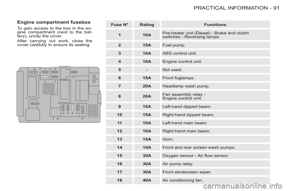
Engine compartment fusebox
To gain access to the box in the en-
gine compartment (next to the bat-
tery), unclip the cover.
After carrying out work, close the
cover carefully to ensure its sealing.
Page 120 of 128

VISUAL INDEX11 8 -
EXTERIOR
Accessories ................................ 97 Key, starting, battery ..........6, 46-47
Central locking .................46, 49-50
Rear lamps ................................. 86
3rd brake lamp............................ 87
Spare wheel, jack,
changing, fi tting ...................79-81
Infl ating tyres ............................ 109
ABS, EBFD, brakes ........ 64, 77, 78
Tyres, pressures ................. 80, 109
Pads, discs, drums ..................... 78
Fuel tank ........... 16, 20, 53, 78, 104 Door mirrors ................................ 57
Snow screen ............................... 94
Front lamps......................54, 82-85
Foglamps .............................. 54, 86
Direction indicators ....54, 82, 85-86
Headlamp adjustment................. 60
Changing bulbs......................82-87
Opening/closing
the doors ...................6, 46, 49-52
Opening the bonnet .............. 16, 53
Side door child lock .................... 51
Locks ...................................... 6, 46 Towbar ........................................ 96
Lifting, towing.............................. 95
Page 123 of 128

121 VISUAL INDEX-
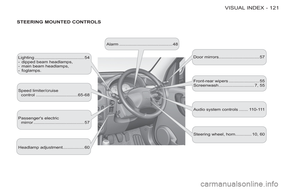
STEERING MOUNTED CONTROLS
Lighting ....................................... 54
- dipped beam headlamps,
- main beam headlamps,
- foglamps.
Speed limiter/cruise
control .................................65-68
Passenger's electric
mirror ........................................ 57 Door mirrors ................................ 57
Headlamp adjustment................. 60 Alarm .......................................... 48
Audio system controls ....... 110-111 Front-rear wipers ........................ 55
Screenwash ............................ 7, 55
Steering wheel, horn............. 10, 60