cooling CITROEN C1 2018 Owners Manual
[x] Cancel search | Manufacturer: CITROEN, Model Year: 2018, Model line: C1, Model: CITROEN C1 2018Pages: 269, PDF Size: 7.63 MB
Page 60 of 269
58
C1_en_Chap03_ergonomie-confort_ed01-2016
For maximum cooling or heating of the cabin, it is possible to go beyond the
m
inimum 14 or maximum 28 value.
F
P
ress the temperature adjustment
b
utton down or up until "LO" or
"HI"
is displayed.
A
setting around 21
gives optimum comfort.
H
owever, depending on your requirements,
a s
etting between 18 and 24 is normal.
On
entering the vehicle, if the interior is very
c
old
or hot, there is no need to change the
v
alue
displayed in order to reach the required
l
evel
of comfort. The system corrects the
t
emperature difference automatically and as
q
uickly as possible.
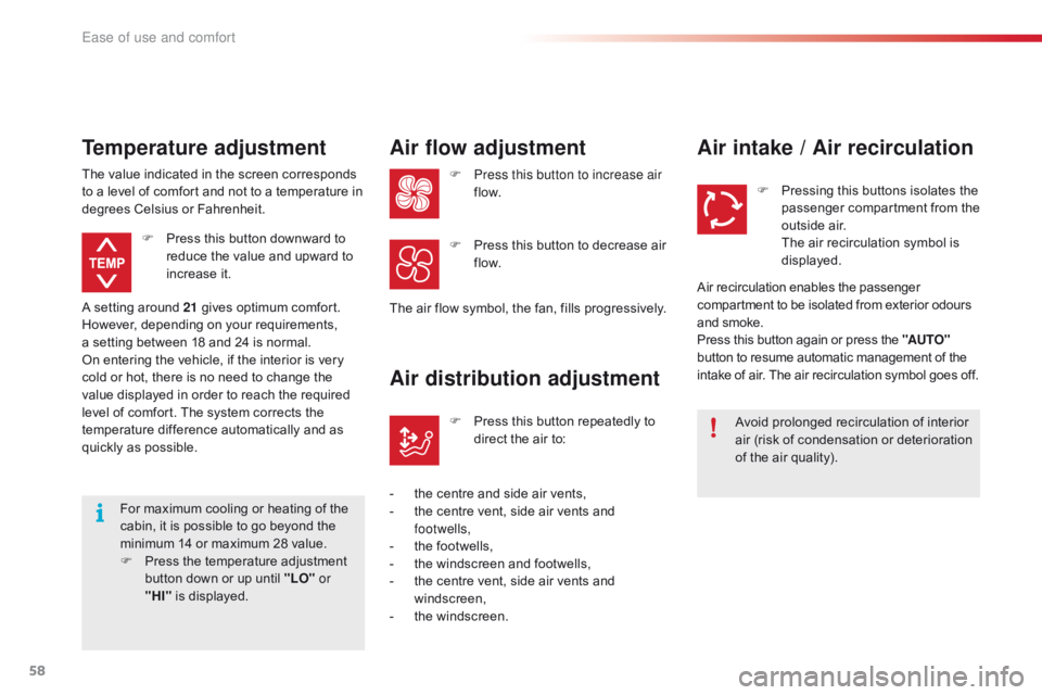
Temperature adjustment
F Press
this button downward to r
educe the value and upward to
inc
rease
it
.
The
value
indicated in the screen corresponds
t
o
a
level
of comfort and not to a temperature in
d
egrees
Celsius or Fahrenheit.
Air flow adjustment
F Press this button to increase air
f low.
The
air
flow symbol, the fan, fills progressively.
F
P
ress this button to decrease air
f
low.
Air distribution adjustment
- the centre and side air vents,
- t he centre vent, side air vents and
f
ootwells,
-
t
he footwells,
-
t
he windscreen and footwells,
-
t
he centre vent, side air vents and
w
indscreen,
-
t
he windscreen.F
P
ress this button repeatedly to
d
irect the air to:
Air intake / Air recirculation
Avoid prolonged recirculation of interior a
ir (risk of condensation or deterioration
o
f the air quality).
F
P
ressing this buttons isolates the
p
assenger compartment from the
o
utside air.
T
he air recirculation symbol is
d
isplayed.
Air
recirculation enables the passenger
c
ompartment to be isolated from exterior odours
a
nd
smoke.
Press
this button again or press the "AUTO"
button
to resume automatic management of the
i
ntake
of air. The air recirculation symbol goes off.
Ease of use and comfort
Page 148 of 269
146
C1_en_Chap07_info-pratiques_ed01-2016
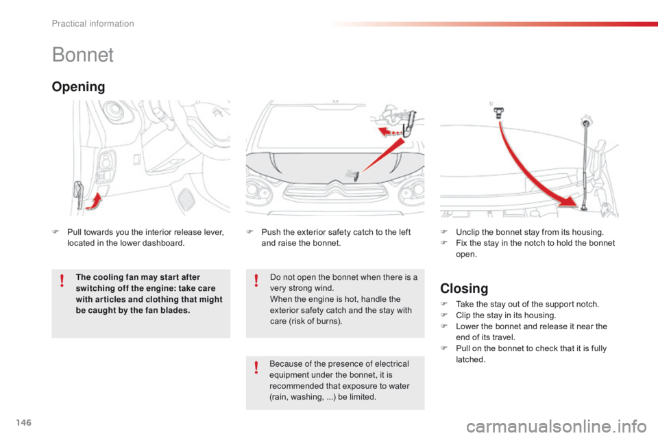
Bonnet
Do not open the bonnet when there is a
very strong wind.
When
the engine is hot, handle the
e
xterior safety catch and the stay with
c
are (risk of burns).
F
P
ush the exterior safety catch to the left
a
nd raise the bonnet.
F
U
nclip the bonnet stay from its housing.
F
F
ix the stay in the notch to hold the bonnet
ope
n.
Opening
F Pull
towards you the interior release lever, l
ocated in the lower dashboard.
The cooling fan may star t after
switching off the engine: take care
with articles and clothing that might
be caught by the fan blades.
Closing
F Take the stay out of the support notch.
F C lip the stay in its housing.
F
L
ower the bonnet and release it near the
e
nd of its travel.
F
P
ull on the bonnet to check that it is fully
l
atched.
Because of the presence of electrical
equipment
under
the
bonnet,
it
is
r
ecommended
that
exposure
to
water
(
rain,
washing,
...)
be
limited.
Practical information
Page 150 of 269
148
C1_en_Chap07_info-pratiques_ed01-2016
Checking levels
Take care when working under the bonnet, as certain areas of the engine
m
ay be extremely hot (risk of burns) and
t
he cooling fan could start at any time
(
even with the ignition off).
Engine oil level
The check of the oil level is carried out with the dipstick, located under
t
he bonnet. For the position of the
d
ipstick, refer to the under-bonnet
v
iew on a previous page.
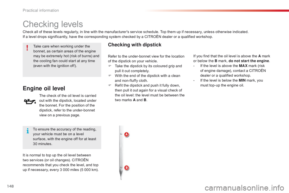
Checking with dipstick
Check all of these levels regularly, in line with the manufacturer's service schedule. Top them up if necessary, unless other wise indicated.
I f a level drops significantly, have the corresponding system checked by a CITROËN dealer or a qualified workshop.
To
ensure the accuracy of the reading,
y
our vehicle must be on a level
s
ur face, with the engine off for at least
3
0 minutes.
It
is normal to top up the oil level between
t
wo services (or oil changes). CITROËN
r
ecommends that you check the level, and top
u
p if necessary, every 3 000 miles (5 000 km). If
you find that the oil level is above the A mark
o
r below the B mark, do not star t the engine.
-
I
f the level is above the MAX
mark (risk
o
f engine damage), contact a CITROËN
d
ealer or a qualified workshop.
-
I
f the level is below the MIN
mark, you
m
ust top-up the engine oil.
Refer
to the under-bonnet view for the location
o
f the dipstick on your vehicle.
F
T
ake the dipstick by its coloured grip and
p
ull it out completely.
F
W
ith the end of the dipstick with a clean
a
nd non-fluffy cloth.
F
R
efit the dipstick and push it fully down,
t
hen pull it out again for a visual check of
t
he oil level: the level must be between the
t
wo marks A and B.
Practical information
Page 152 of 269
150
C1_en_Chap07_info-pratiques_ed01-2016
Avoid prolonged contact of used oil or fluids with the skin.
Most
of these fluids are harmful to
h
ealth or indeed very corrosive.
Do
not discard used oil or fluids into
s
ewers or onto the ground.
Take
used oil to a CITROËN dealer or
a
qualified workshop (France) or to an
a
uthorised waste disposal site.
Used products
Fluid specification
For optimum cleaning and to avoid freezing, this fluid must not be topped up or replaced
w
ith plain water.
In
w
intry
c
onditions,
i
t
i
s
r
ecommended
t
hat
y
ou
u
se an ethyl alcohol or methanol based fluid.
Screenwash fluid level
Top up the level when necessary.
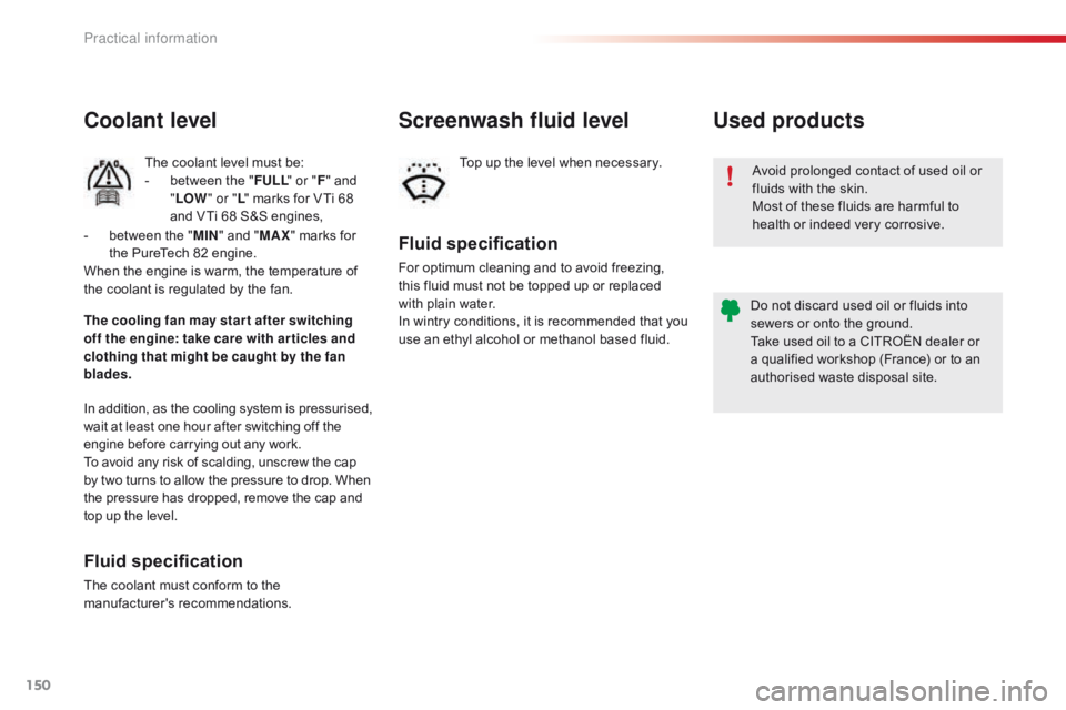
Coolant level
The coolant level must be:
- b etween the "FULL " or "F"
and
"LO
W" or " L"
marks for VTi 68
a
nd VTi 68 S&S engines,
In
addition, as the cooling system is pressurised,
w
ait
at
least one hour after switching off the
e
ngine
before carrying out any work.
To
avoid
any risk of scalding, unscrew the cap
b
y
two
turns to allow the pressure to drop. When
t
he
pressure has dropped, remove the cap and
t
op
up
the
level.
Fluid specification
The coolant must conform to the ma nufacturer's r ecommendations.
The cooling fan may star t after switching
off the engine: take care with ar ticles and
clothing that might be caught by the fan
blades. -
b
etween the "
MIN " and "
MAX " marks for
t
he PureTech 82 engine.
When the engine is warm, the temperature of
t
he coolant is regulated by the fan.
Practical information
Page 172 of 269
170
C1_en_Chap08_en-cas-pannes_ed01-2016
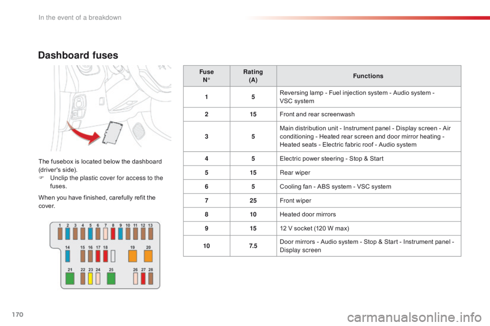
Dashboard fuses
The fusebox is located below the dashboard (driver's side).
F
U
nclip the plastic cover for access to the
fuses.
When
you have finished, carefully refit the
c
ove r. Fuse
N° Rating
(A) Functions
1 5Reversing lamp - Fuel injection system - Audio system -
V
SC system
2 15Front and rear screenwash
3 5Main distribution unit - Instrument panel - Display screen - Air
c
onditioning - Heated rear screen and door mirror heating -
H
eated seats - Electric fabric roof - Audio system
4 5Electric power steering - Stop & Start
5 15Rear wiper
6 5Cooling
fan - ABS system - VSC system
7 25Front wiper
8 10Heated
door mirrors
9 1512
V socket (120 W max)
10 7. 5Door
mirrors - Audio system - Stop & Start - Instrument panel -
D
isplay screen
In the event of a breakdown
Page 175 of 269
173
C1_en_Chap08_en-cas-pannes_ed01-2016
Fuse
N° Rating
(A) Functions
1 10Right
hand dipped beam
2 10Left
hand dipped beam - Headlamp adjustment
3 7. 5Right
hand main beam
4 7. 5Left
hand main beam
5 * 15Fuel
injection system
6 * 7. 5Fuel
injection system
7 * 15Fuel
injection system
8 * 7. 5Cooling
fan
9 7. 5Air
c
onditioning
10 ** 7. 5Fuel
injection system - Brake lamps - Third brake lamp
11 5Courtesy
lamp - Boot lamp
12 10
Direction indicators - Hazard warning lamps - Instrument panel - Display screen
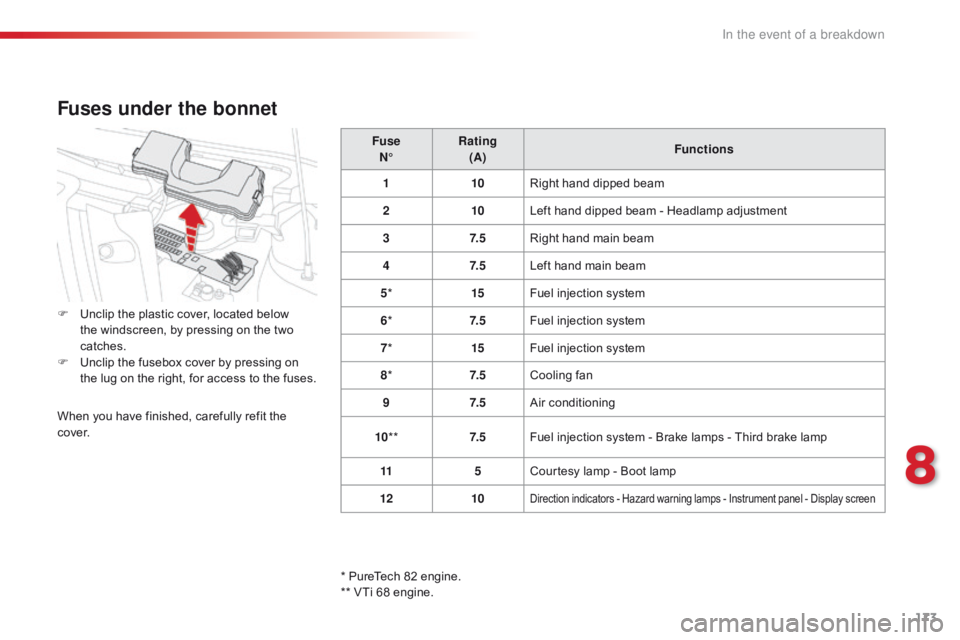
Fuses under the bonnet
F Unclip the plastic cover, located below t
he windscreen, by pressing on the two
c
atches.
F
U
nclip the fusebox cover by pressing on
t
he lug on the right, for access to the fuses.
When
you have finished, carefully refit the
c
ove r.
*
PureTech 82 engine.
**
VTi 68 engine.
8
In the event of a breakdown
Page 176 of 269
174
C1_en_Chap08_en-cas-pannes_ed01-2016
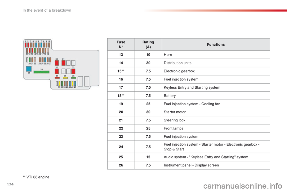
** VTi 68 engine.F use
N° Rating
(A) Functions
13 10Horn
14 30Distribution units
15 ** 7. 5Electronic
g
earbox
16 7. 5Fuel injection system
17 7. 0Keyless Entry and Starting system
18 ** 7. 5Battery
19 25Fuel injection system - Cooling fan
20 30Starter motor
21 7. 5Steering lock
22 25Front lamps
23 7. 5Fuel injection system
24 7. 5Fuel injection system - Starter motor - Electronic gearbox -
Stop & Start
25 15Audio system - "Keyless Entry and Starting" system
26 7. 5Instrument panel - Display screen
In the event of a breakdown
Page 177 of 269
175
C1_en_Chap08_en-cas-pannes_ed01-2016
FuseN° Rating
(A) Functions
27 7. 5VSC
system
28 60Passenger
c
ompartment
f
usebox
29** 125***Heated
rear screen and door mirror heating - Heated seats -
Electric
fabric roof - ABS system - VSC system - Cooling fan -
L
ED daytime running lamps
30 50
Electronic
g
earbox
40 Stop & Start
31 50Power
s
teering
32 50*
Cooling
fan
30
40
33 50ABS
system - VSC system
34 10Spare fuse
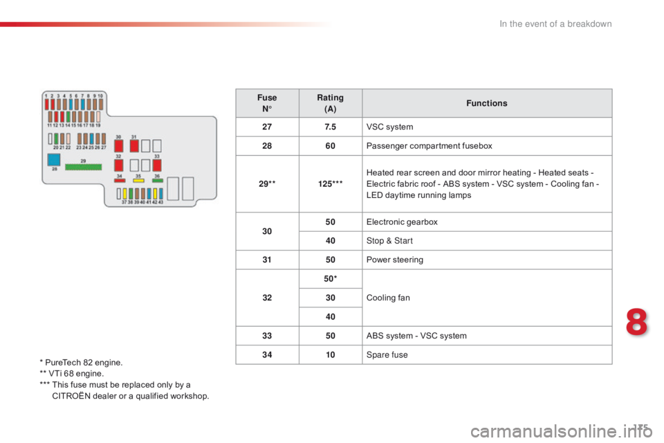
*
PureTech
82
engine.
**
VTi
68
engine.
***
T
his
fuse
must
be
replaced
only
by
a
C
ITROËN
dealer
or
a
qualified
workshop.
8
In the event of a breakdown
Page 180 of 269
178
C1_en_Chap08_en-cas-pannes_ed01-2016
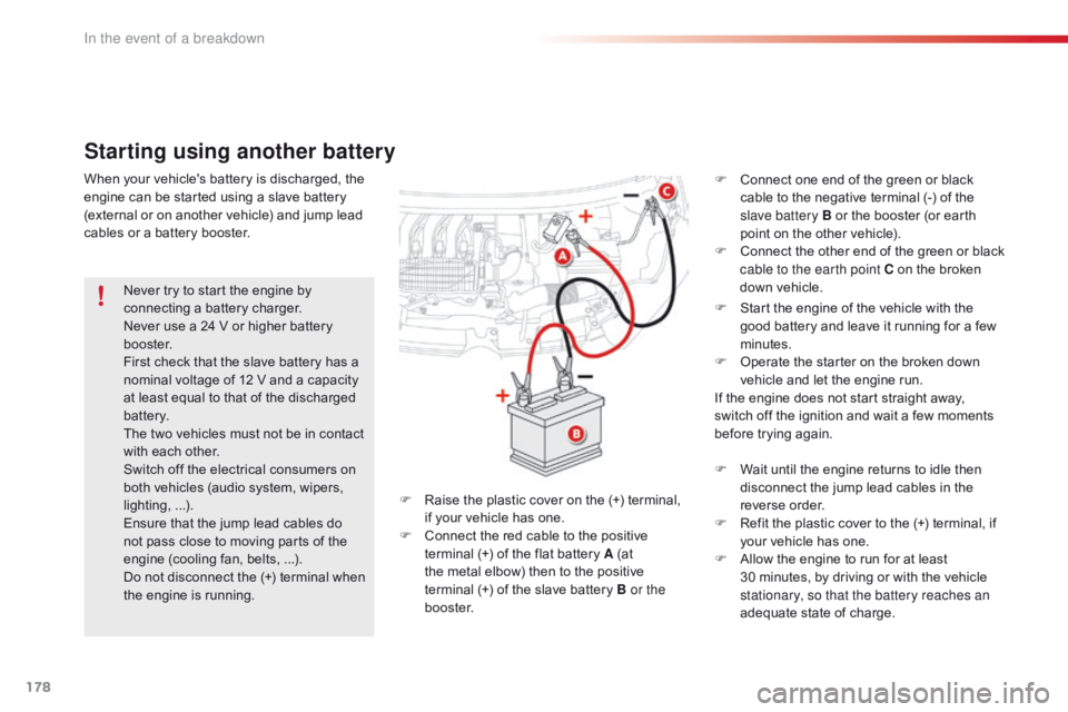
Starting using another battery
F Start the engine of the vehicle with the g
ood battery and leave it running for a few
m
inutes.
F
O
perate the starter on the broken down
v
ehicle and let the engine run.
If
the engine does not start straight away,
s
witch off the ignition and wait a few moments
b
efore trying again.
Never
try
to
start
the
engine
by
c
onnecting
a
battery
charger.
Never
use
a
24
V
or
higher
battery
b
o o s t e r.
First
check
that
the
slave
battery
has
a
n
ominal
voltage
of
12
V
and
a
capacity
a
t
least
equal
to
that
of
the
discharged
b
attery.
The
two
vehicles
must
not
be
in
contact
w
ith
each
other.
Switch
off
the
electrical
consumers
on
b
oth
vehicles
(audio
system,
wipers,
l
ighting,
...
).
Ensure
that
the
jump
lead
cables
do
n
ot
pass
close
to
moving
parts
of
the
e
ngine
(cooling
fan,
belts,
...).
Do
not
disconnect
the
(+)
terminal
when
t
he
engine
is
running. F
W
ait until the engine returns to idle then
d
isconnect the jump lead cables in the
r
everse
o
rder.
F
R
efit the plastic cover to the (+) terminal, if
y
our vehicle has one.
F
A
llow the engine to run for at least
3
0 minutes, by driving or with the vehicle
s
tationary, so that the battery reaches an
adequate
state of charge.
When
your
vehicle's
battery
is
discharged,
the
e
ngine
can
be
started
using
a
slave
battery
(
external
or
on
another
vehicle)
and
jump
lead
c
ables
or
a
battery
booster.
F
R
aise
the
plastic
cover
on
the
(+)
terminal,
i
f
your
vehicle
has
one.
F
C
onnect
the
red
cable
to
the
positive
t
erminal
(+)
of
the
flat
battery
A
(at
t
he
metal
elbow)
then
to
the
positive
t
erminal (+)
of
the
slave
battery
B or the
b o o s t e r. F
C
onnect one end of the green or black
c
able to the negative terminal (-) of the
s
lave battery B or the booster (or earth
p
oint on the other vehicle).
F
C
onnect
t
he
o
ther
e
nd
o
f
t
he
g
reen
o
r
b
lack
c
able to the earth point C on the broken
d
own vehicle.
In the event of a breakdown