par Citroen C3 2004 1.G Manual PDF
[x] Cancel search | Manufacturer: CITROEN, Model Year: 2004, Model line: C3, Model: Citroen C3 2004 1.GPages: 523, PDF Size: 10.32 MB
Page 493 of 523

Downloaded from www.Manualslib.com manuals search engine 489
ELECTRICAL
SYSTEM
SPECIAL FEATURES: AIR CONDITIONING SYSTEM (R 134.a)
Pollen filter
Note:
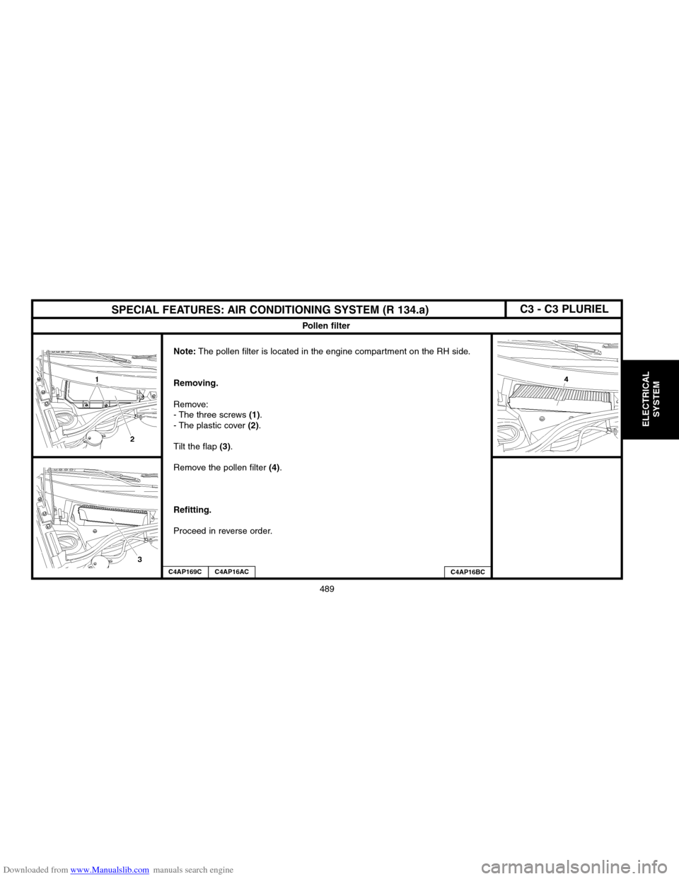
The pollen filter is located in the engine compartment on the RH side.
Removing.
Remove:
� The three screws (1).
� The plastic cover (2).
Tilt the flap
(3).
Remove the pollen filter
(4).
Refitting.
Proceed in reverse order.
C4AP169CC4AP16ACC4AP16BC
C3 � C3 PLURIEL
Page 502 of 523

Downloaded from www.Manualslib.com manuals search engine 498
AIRCONAIRCON
AIR CONDITIONING SYSTEM R 134.a
Testing procedure
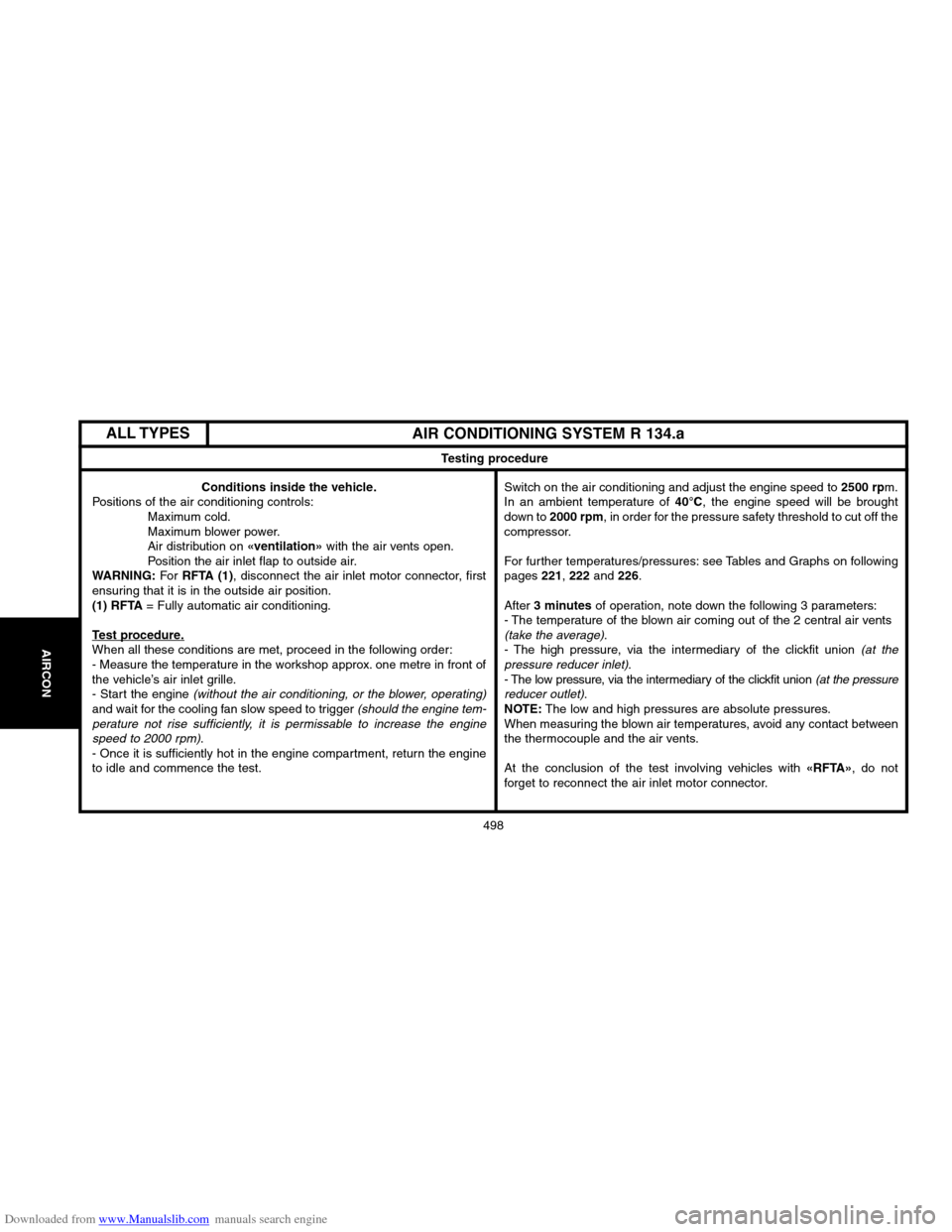
Conditions inside the vehicle.
Positions of the air conditioning controls:
Maximum cold.
Maximum blower power.
Air distribution on
«ventilation»with the air vents open.
Position the air inlet flap to outside air.
WARNING:For RFTA (1), disconnect the air inlet motor connector, first
ensuring that it is in the outside air position.
(1) RFTA= Fully automatic air conditioning.
Test procedure.When all these conditions are met, proceed in the following order:
� Measure the temperature in the workshop approx. one metre in front of
the vehicle’s air inlet grille.
� Start the engine
(without the air conditioning, or the blower, operating)and wait for the cooling fan slow speed to trigger (should the engine tem�
perature not rise sufficiently, it is permissable to increase the engine
speed to 2000 rpm)
.
� Once it is sufficiently hot in the engine compartment, return the engine
to idle and commence the test.Switch on the air conditioning and adjust the engine speed to
2500 rpm.
In an ambient temperature of 40°C, the engine speed will be brought
down to 2000 rpm, in order for the pressure safety threshold to cut off the
compressor.
For further temperatures/pressures: see Tables and Graphs on following
pages
221, 222 and 226.
After
3 minutesof operation, note down the following 3 parameters:
� The temperature of the blown air coming out of the 2 central air vents
(take the average).
� The high pressure, via the intermediary of the clickfit union (at the
pressure reducer inlet).
� The low pressure, via the intermediary of the clickfit union (at the pressure
reducer outlet).NOTE:The low and high pressures are absolute pressures.
When measuring the blown air temperatures, avoid any contact between
the thermocouple and the air vents.
At the conclusion of the test involving vehicles with
«RFTA»
ALL TYPES
Page 504 of 523

Downloaded from www.Manualslib.com manuals search engine 500
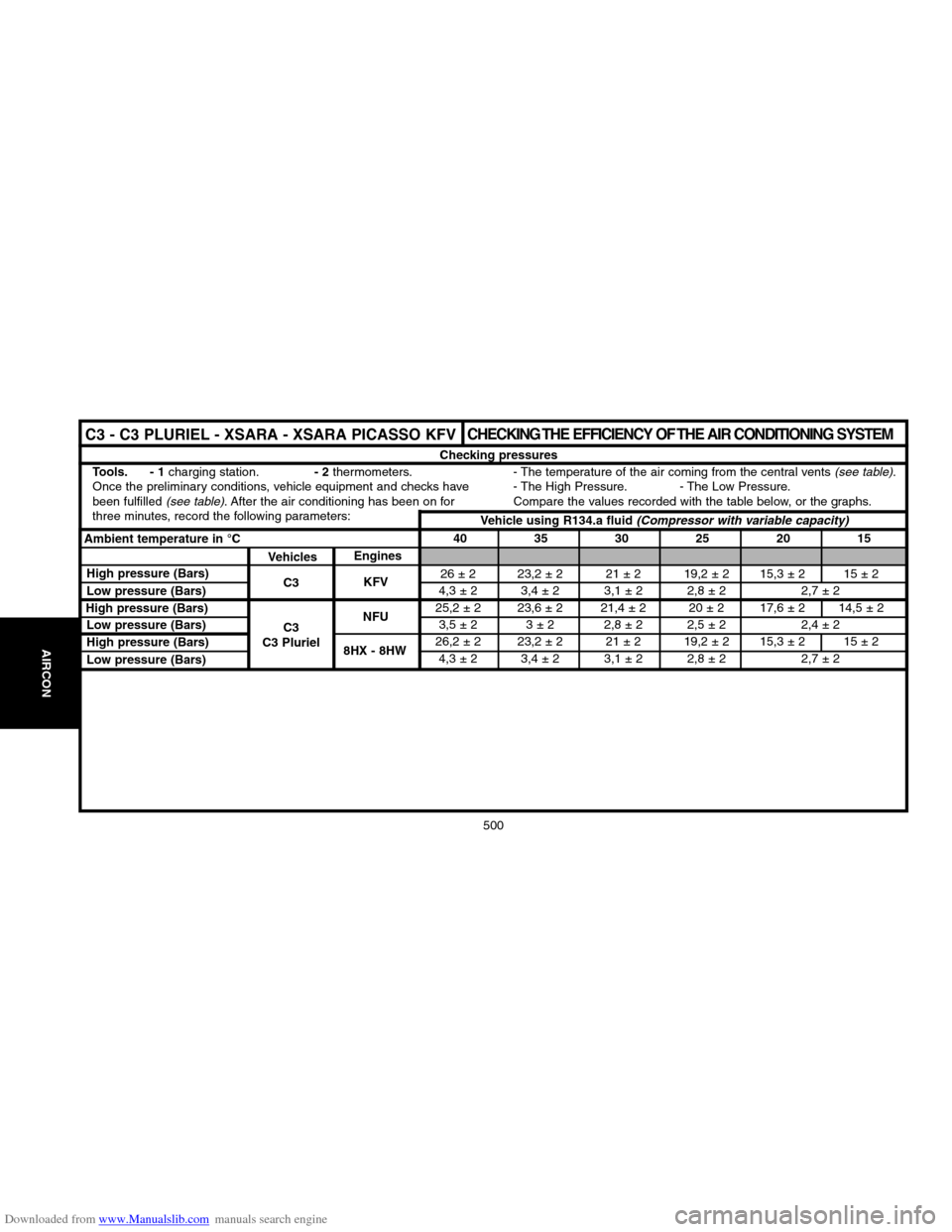
26 ± 2 23,2 ± 2 21 ± 2 19,2 ± 2 15,3 ± 2 15 ± 2
4,3 ±2 3,4 ± 2 3,1 ± 2 2,8 ± 2 2,7 ± 2
25,2 ±223,6 ± 2 21,4 ± 2 20 ± 2 17,6 ± 2 14,5 ± 2
3,5 ± 2 3 ± 2 2,8 ± 2 2,5 ± 2 2,4 ± 2
26,2 ± 2 23,2 ± 2 21 ± 2 19,2 ± 2 15,3 ± 2 15 ± 2
4,3 ± 2 3,4 ± 2 3,1 ± 2 2,8 ± 2 2,7 ± 2
CHECKING THE EFFICIENCY OF THE AIR CONDITIONING SYSTEM
Checking pressures
Tools. � 1
charging station.� 2thermometers.
Once the preliminary conditions, vehicle equipment and checks havebeen fulfilled
(see table). After the air conditioning has been on for
three minutes, record the following parameters:� The temperature of the air coming from the central vents
(see table).
� The High Pressure. � The Low Pressure.
Compare the values recorded with the table below, or the graphs.
Ambient temperature in °C40 35 30 25 20 15
VehiclesEngines
C3
C3
C3 PlurielKFV
NFUHigh pressure (Bars)
Low pressure (Bars)
Low pressure (Bars)
High pressure (Bars)
Low pressure (Bars)8HX � 8HWVehicle using R134.a fluid
(Compressor with variable capacity)
High pressure (Bars)
AIRCONAIRCON
C3 � C3 PLURIEL � XSARA � XSARA PICASSO KFV
Page 505 of 523

Downloaded from www.Manualslib.com manuals search engine 501
AIRCON
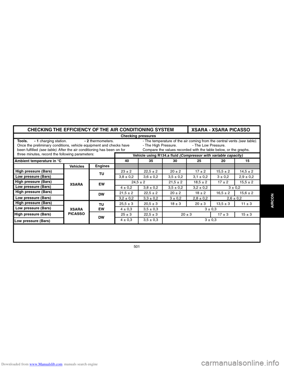
23 ± 2 22,5 ± 2 20 ± 2 17 ± 2 15,5 ± 2 14,5 ± 2
3,8 ± 0,2 3,6 ± 0,2 3,5 ± 0,2 3,1 ± 0,2 3 ± 0,2 2,9 ± 0,2
24,5 ±221,5 ±2 18,5 ± 2 17 ± 2 15,5 ± 2
4 ±0,2 3,8 ± 0,2 3,5 ± 0,2 3,2 ± 0,2 3 ± 0,2
21,5 ± 2 22,5 ± 2 20 ± 2 18 ± 2 16,5 ± 2 15,6 ± 2
3,2 ±0,23,3 ±0,23 ±0,22,8 ± 0,2 2,6 ± 0,2
25,5 ±320,5 ±318 ± 3 20 ± 3 13,5 ± 3 11 ± 3
4 ±0,33,5 ± 0,3 3 ± 0,3
25 ± 3 22,5 ± 3 20 ± 3 17 ± 3 15 ± 3
4 ±0,33,5 ± 0,3 3 ± 0,3
CHECKING THE EFFICIENCY OF THE AIR CONDITIONING SYSTEM
Checking pressures
Tools. � 1
charging station.� 2thermometers.
Once the preliminary conditions, vehicle equipment and checks havebeen fulfilled
(see table). After the air conditioning has been on for
three minutes, record the following parameters:� The temperature of the air coming from the central vents
(see table).
� The High Pressure. � The Low Pressure.
Compare the values recorded with the table below, or the graphs.
Ambient temperature in °C40 35 30 25 20 15
VehiclesEngines
XSARA
XSARA
PICASSOTU
EW
High pressure (Bars)
Low pressure (Bars)
Low pressure (Bars)
High pressure (Bars)
Low pressure (Bars)DWVehicle using R134.a fluid
(Compressor with variable capacity)
High pressure (Bars)
XSARA � XSARA PICASSO
High pressure (Bars)
Low pressure (Bars)
High pressure (Bars)
Low pressure (Bars)
TU
EW
DW