Front grill Citroen C3 2004 1.G Workshop Manual
[x] Cancel search | Manufacturer: CITROEN, Model Year: 2004, Model line: C3, Model: Citroen C3 2004 1.GPages: 523, PDF Size: 10.32 MB
Page 494 of 523
![Citroen C3 2004 1.G Workshop Manual Downloaded from www.Manualslib.com manuals search engine 490
AIRCONAIRCON
SPECIAL FEATURES: AIR CONDITIONING SYSTEM (R 134.a)
Changing the filtering/drying cartridge
Tools.
[1]
Charge station :(accord Citroen C3 2004 1.G Workshop Manual Downloaded from www.Manualslib.com manuals search engine 490
AIRCONAIRCON
SPECIAL FEATURES: AIR CONDITIONING SYSTEM (R 134.a)
Changing the filtering/drying cartridge
Tools.
[1]
Charge station :(accord](/img/9/4135/w960_4135-493.png)
Downloaded from www.Manualslib.com manuals search engine 490
AIRCONAIRCON
SPECIAL FEATURES: AIR CONDITIONING SYSTEM (R 134.a)
Changing the filtering/drying cartridge
Tools.
[1]
Charge station :(according to workshop equipment)[2]TORX adaptor: TORX 70 FACOM
[3]Inertia extractor:1671�T Tool kit 4114�T
[4]Endpiece Ø 20 : 1671�T.D20
[5]Set of plugs: (�).0188.T
[6]Circlip pliers: FACOM
Removing.
Depressurise the aircon circuit, using tool [1].
Remove the grille.At
«a», remove the pin and the plastic cover.
Unclip the condenser at «b»and «c», using a screwdriver.
Tilt the condenser towards the front.
Lift and release the condenser.Clean the area around the cap
(3).
Remove the plastic cap (3), using tool [2].
Remove the safety circlip (4), using tool [6].
Position the tool [3]and[4]in the aperture of the cartridge (5).
Extract the cartridge from the reservoir (6), using tool [3]and [4].
Block the reservoir (6), using tool [5].
C4AP163CC4AP164CC4AP166CC4AP165C
C2 � C3 � C3 PLURIEL
Page 502 of 523

Downloaded from www.Manualslib.com manuals search engine 498
AIRCONAIRCON
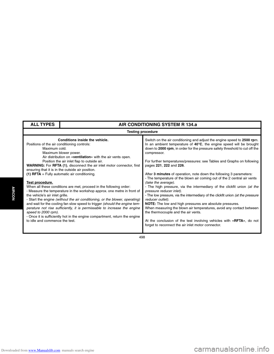
AIR CONDITIONING SYSTEM R 134.a
Testing procedure
Conditions inside the vehicle.
Positions of the air conditioning controls:
Maximum cold.
Maximum blower power.
Air distribution on
«ventilation»with the air vents open.
Position the air inlet flap to outside air.
WARNING:For RFTA (1), disconnect the air inlet motor connector, first
ensuring that it is in the outside air position.
(1) RFTA= Fully automatic air conditioning.
Test procedure.When all these conditions are met, proceed in the following order:
� Measure the temperature in the workshop approx. one metre in front of
the vehicle’s air inlet grille.
� Start the engine
(without the air conditioning, or the blower, operating)and wait for the cooling fan slow speed to trigger (should the engine tem�
perature not rise sufficiently, it is permissable to increase the engine
speed to 2000 rpm)
.
� Once it is sufficiently hot in the engine compartment, return the engine
to idle and commence the test.Switch on the air conditioning and adjust the engine speed to
2500 rpm.
In an ambient temperature of 40°C, the engine speed will be brought
down to 2000 rpm, in order for the pressure safety threshold to cut off the
compressor.
For further temperatures/pressures: see Tables and Graphs on following
pages
221, 222 and 226.
After
3 minutesof operation, note down the following 3 parameters:
� The temperature of the blown air coming out of the 2 central air vents
(take the average).
� The high pressure, via the intermediary of the clickfit union (at the
pressure reducer inlet).
� The low pressure, via the intermediary of the clickfit union (at the pressure
reducer outlet).NOTE:The low and high pressures are absolute pressures.
When measuring the blown air temperatures, avoid any contact between
the thermocouple and the air vents.
At the conclusion of the test involving vehicles with
«RFTA»
ALL TYPES