Citroen C3 2017 2.G Owner's Manual
Manufacturer: CITROEN, Model Year: 2017, Model line: C3, Model: Citroen C3 2017 2.GPages: 450, PDF Size: 10.11 MB
Page 221 of 450
219
B618_en_Chap07_info-pratiques_ed01-2016
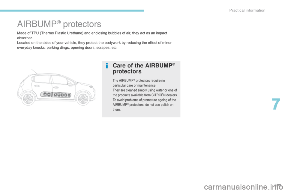
Made of TPU (Thermo Plastic Urethane) and enclosing bubbles of air, they act as an impact
a b s o r b e r.
Located on the sides of your vehicle, they protect the bodywork by reducing the effect of minor
everyday knocks: parking dings, opening doors, scrapes, etc.
AIRBUMP® protectors
Care of the AIRBUMP®
protectors
The AIRBUMP® protectors require no
particular care or maintenance.
They are cleaned simply using water or one of
the products available from CITROËN dealers.
To avoid problems of premature ageing of the
AIRBUMP
® protectors, do not use polish on
them.
7
Practical information
Page 222 of 450
220
B618_en_Chap08_En-cas-de-panne_ed01-2016
Warning triangle
The triangle can be stored on the rear face of
the boot, secured by straps.
Assembling the triangle
As a safety precaution, before leaving your
vehicle to set up and install the triangle, switch
on the hazard warning lamps and put on your
high visibility vest.Refer to the instructions provided with the
triangle.
Positioning the triangle
Running out of fuel
(Diesel)
On vehicles fitted with Diesel engines, the fuel
system must be primed if you run out of fuel. For more information on Misfuel
prevention (Diesel) , refer to the
corresponding section.
If the engine does not start first
time, don't keep trying, but start the
procedure again from the beginning.
BlueHDi engines
F Fill the fuel tank with at least five litres of Diesel.
F
S
witch on the ignition (without starting the
engine).
F
W
ait around 6 seconds and switch off the
ignition.
F
R
epeat the operation 10 times.
F
O
perate the starter to run the engine.
F
P
lace the triangle behind the vehicle, as
required by local legislation.
Other HDi engines
(except BlueHDi version)
F A dd at least five litres of Diesel fuel to the
tank.
F
O
pen the bonnet.
F
I
f necessary, unclip the styling cover for
access to the priming pump.
F
S
queeze and release the priming pump
repeatedly until resistance is felt (there
may be resistance at the first press).
F
O
perate the starter to start the engine
(if the engine does not start at the first
attempt, wait around 15 seconds before
trying again).
F
I
f the engine does not start after a few
attempts, operate the priming pump again
then start the engine.
F
R
efit the styling cover and clip it in place.
F
C
lose the bonnet.
In the event of a breakdown
Page 223 of 450
221
B618_en_Chap08_En-cas-de-panne_ed01-2016
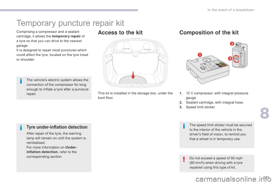
1. 12 V compressor, with integral pressure gauge.
2.
S
ealant cartridge, with integral hose.
3.
S
peed limit sticker.
Composition of the kit
The speed limit sticker must be secured
to the interior of the vehicle in the
driver's field of vision, to remind you
that a wheel is in temporary use.
The vehicle's electric system allows the
connection of the compressor for long
enough to inflate a tyre after a puncture
repair.
This kit is installed in the storage box, under the
boot floor.
Comprising a compressor and a sealant
cartridge, it allows the temporary repair
of
a tyre so that you can drive to the nearest
garage.
It is designed to repair most punctures which
could affect the tyre, located on the tyre tread
or shoulder.
Temporary puncture repair kit
Access to the kit
Do not exceed a speed of 50 mph
(80 km/h) when driving with a tyre
repaired using this type of kit.
Tyre under-inflation detection
After repair of the tyre, the warning
lamp will remain on until the system is
reinitialised.
For more information on Under-
inflation detection , refer to the
corresponding section.
8
In the event of a breakdown
Page 224 of 450

222
B618_en_Chap08_En-cas-de-panne_ed01-2016
F Switch off the ignition.
F S ecure the speed limit sticker inside the
vehicle.
Repair procedure
Avoid removing any foreign bodies
which have penetrated into the tyre. F
T
urn the sealant cartridge and secure it in
the cut-out provided on the compressor. F
R
emove the valve cap from the tyre to be
repaired, and place it in a clean area.
F
C
onnect the hose from the sealant
cartridge to the valve of the tyre to be
repaired and tighten firmly.
F
U
ncoil the pipe stowed under the
compressor.
F
C
onnect the pipe from the compressor to
the sealant cartridge.
In the event of a breakdown
Page 225 of 450
223
B618_en_Chap08_En-cas-de-panne_ed01-2016
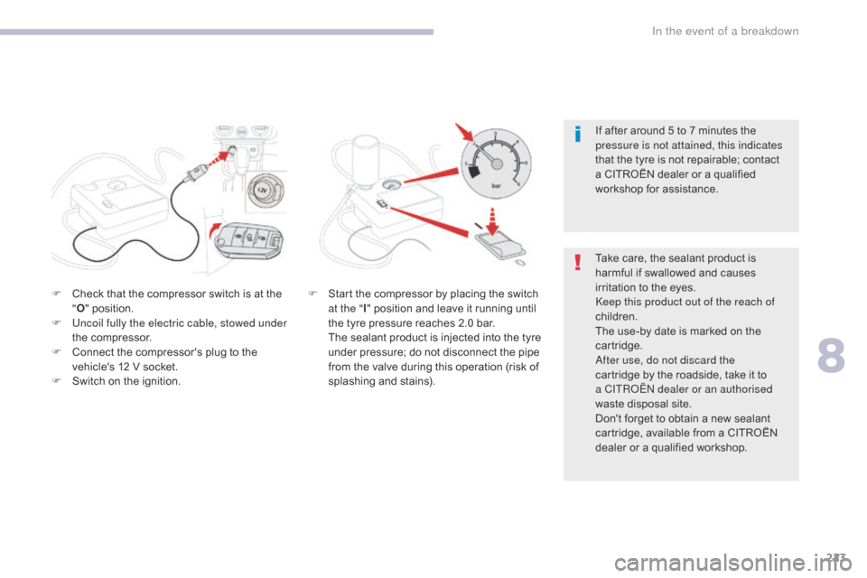
F Check that the compressor switch is at the "O " position.
F
U
ncoil fully the electric cable, stowed under
the compressor.
F
C
onnect the compressor's plug to the
vehicle's 12 V socket.
F
S
witch on the ignition. If after around 5 to 7 minutes the
pressure is not attained, this indicates
that the tyre is not repairable; contact
a CITROËN dealer or a qualified
workshop for assistance.
F S tart the compressor by placing the switch
at the " I" position and leave it running until
the tyre pressure reaches 2.0 bar.
T
he sealant product is injected into the tyre
under pressure; do not disconnect the pipe
from the valve during this operation (risk of
splashing and stains). Take care, the sealant product is
harmful if swallowed and causes
irritation to the eyes.
Keep this product out of the reach of
children.
The use-by date is marked on the
cartridge.
After use, do not discard the
cartridge by the roadside, take it to
a CITROËN
dealer or an authorised
waste disposal site.
Don't forget to obtain a new sealant
cartridge, available from a CITROËN
dealer or a qualified workshop.
8
In the event of a breakdown
Page 226 of 450
224
B618_en_Chap08_En-cas-de-panne_ed01-2016
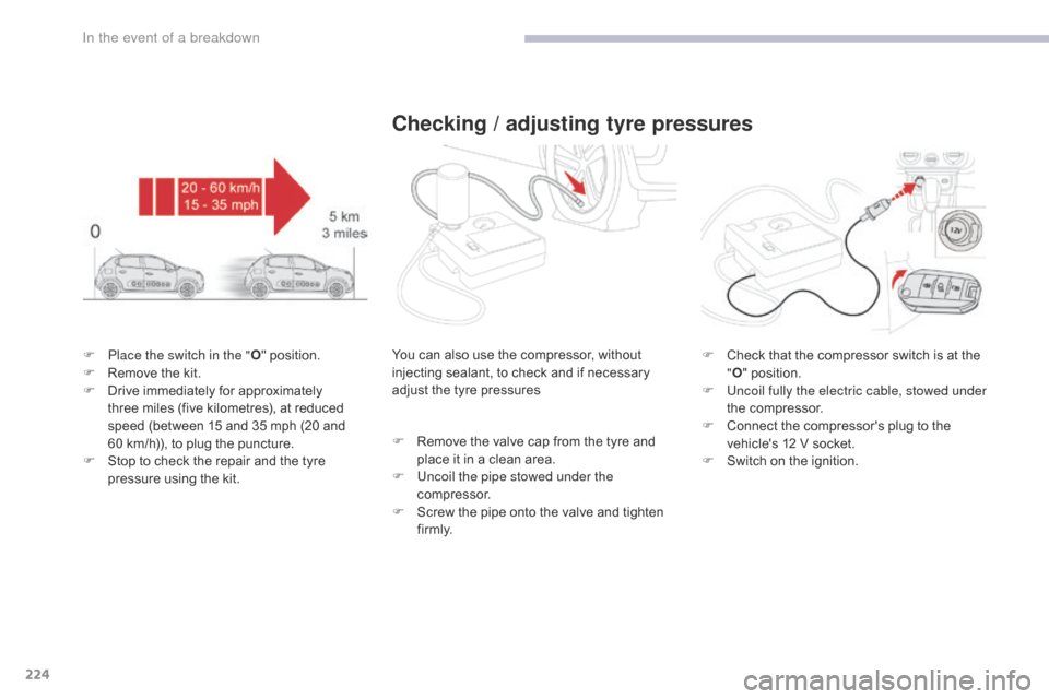
F Place the switch in the "O" position.
F R emove the kit.
F
D
rive immediately for approximately
three miles (five kilometres), at reduced
speed (between 15 and 35 mph (20 and
60
km/h)), to plug the puncture.
F
S
top to check the repair and the tyre
pressure using the kit.
Checking / adjusting tyre pressures
You can also use the compressor, without
injecting sealant, to check and if necessary
adjust the tyre pressures
F
R
emove the valve cap from the tyre and
place it in a clean area.
F
U
ncoil the pipe stowed under the
compressor.
F
S
crew the pipe onto the valve and tighten
f i r m l y. F
C heck that the compressor switch is at the
" O " position.
F
U
ncoil fully the electric cable, stowed under
the compressor.
F
C
onnect the compressor's plug to the
vehicle's 12 V socket.
F
S
witch on the ignition.
In the event of a breakdown
Page 227 of 450
225
B618_en_Chap08_En-cas-de-panne_ed01-2016
Should the pressure of one or more
tyres be adjusted, it is necessary to
reinitialise the under-inflation detection
system.
For more information on Under-
inflation detection, refer to the
corresponding section.
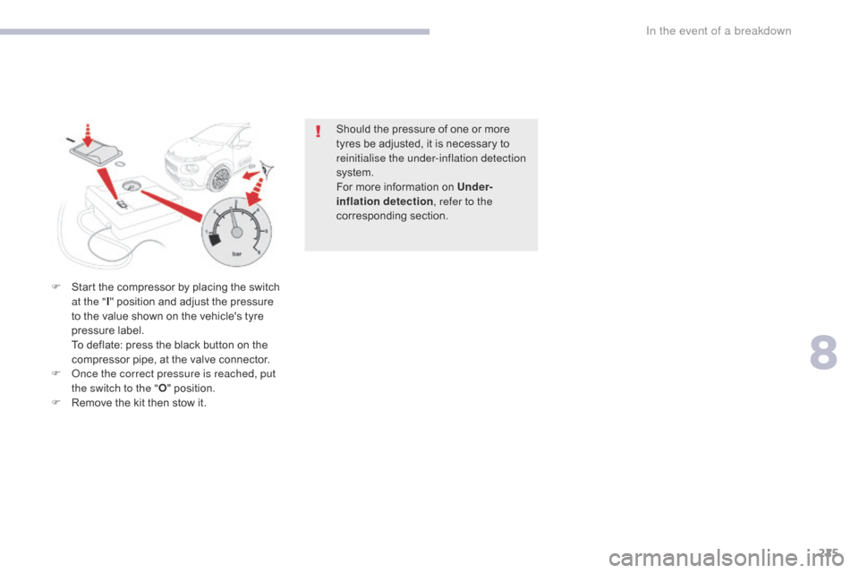
F
S
tart the compressor by placing the switch
at the " I" position and adjust the pressure
to the value shown on the vehicle's tyre
pressure label.
T
o deflate: press the black button on the
compressor pipe, at the valve connector.
F
O
nce the correct pressure is reached, put
the switch to the " O" position.
F
R
emove the kit then stow it.
8
In the event of a breakdown
Page 228 of 450
226
B618_en_Chap08_En-cas-de-panne_ed01-2016
Spare wheel
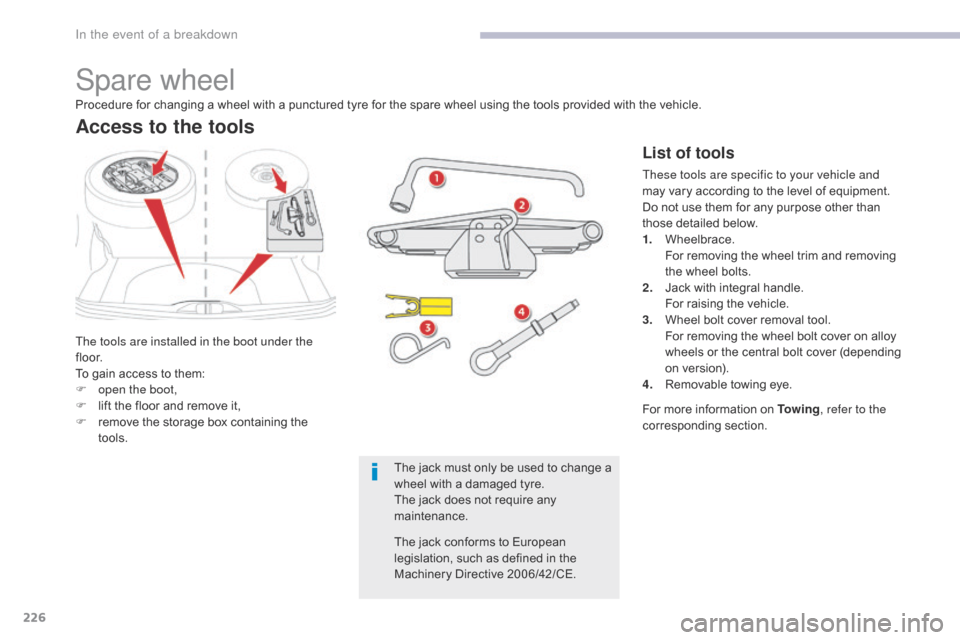
The tools are installed in the boot under the
f l o o r.
To gain access to them:
F
o
pen the boot,
F
l
ift the floor and remove it,
F
r
emove the storage box containing the
tools.
Access to the tools
List of tools
These tools are specific to your vehicle and
may vary according to the level of equipment.
Do not use them for any purpose other than
those detailed below.
1.
W
heelbrace.
F
or removing the wheel trim and removing
the wheel bolts.
2.
J
ack with integral handle.
F
or raising the vehicle.
3.
W
heel bolt cover removal tool.
F
or removing the wheel bolt cover on alloy
wheels or the central bolt cover (depending
on version).
4.
R
emovable towing eye.
Procedure for changing a wheel with a punctured tyre for the spare wheel using the tools provided with the vehicle.
For more information on To w i n g, refer to the
corresponding section.
The jack must only be used to change a
wheel with a damaged tyre.
The jack does not require any
maintenance.
The jack conforms to European
legislation, such as defined in the
Machinery Directive 2006/42/CE.
In the event of a breakdown
Page 229 of 450

227
B618_en_Chap08_En-cas-de-panne_ed01-2016
Taking out the wheel
F Unclip the tool storage box (standard spare wheel).
F
U
nscrew the central nut.
F
R
emove the fixing parts (nut and bolt).
F
R
aise the spare wheel towards you from
the rear.
F
T
ake the wheel out of the boot.
The spare wheel is installed in the boot under
the floor.
Depending on engine, the spare wheel is
a standard wheel or the space-saver type
(BlueHDi).
Access to the spare wheel
8
In the event of a breakdown
Page 230 of 450
228
B618_en_Chap08_En-cas-de-panne_ed01-2016
Putting the wheel back in place
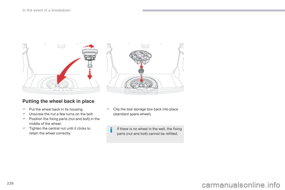
F Put the wheel back in its housing.
F U nscrew the nut a few turns on the bolt.
F
P
osition the fixing parts (nut and bolt) in the
middle of the wheel.
F
T
ighten the central nut until it clicks to
retain the wheel correctly. F
C lip the tool storage box back into place
(standard spare wheel).
If there is no wheel in the well, the fixing
parts (nut and bolt) cannot be refitted.
In the event of a breakdown