height adjustment CITROEN C3 AIRCROSS 2022 Owners Manual
[x] Cancel search | Manufacturer: CITROEN, Model Year: 2022, Model line: C3 AIRCROSS, Model: CITROEN C3 AIRCROSS 2022Pages: 308, PDF Size: 9.13 MB
Page 7 of 308
5
OFF
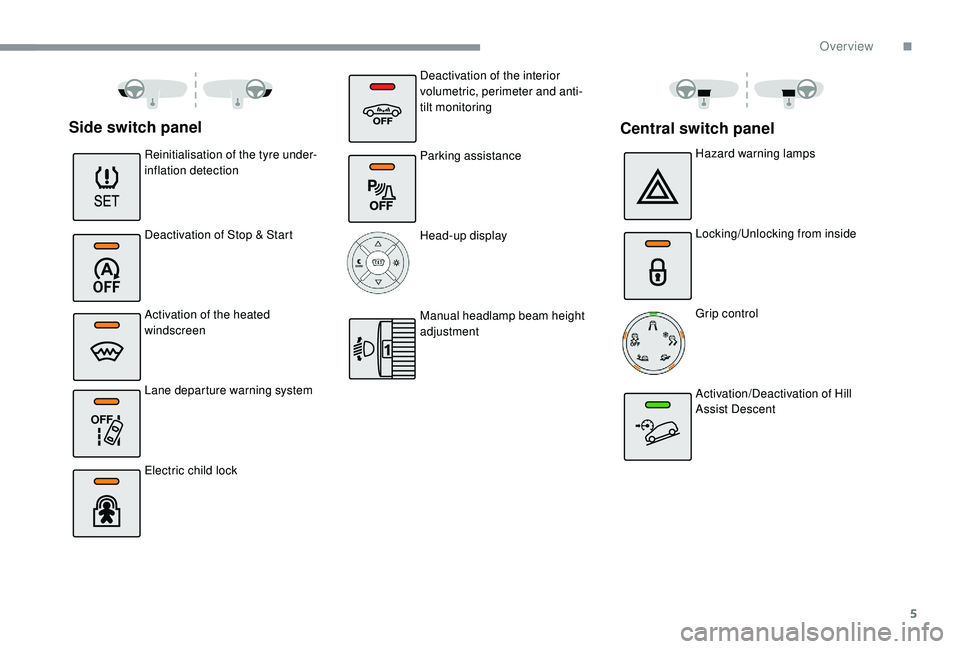
Side switch panel
Reinitialisation of the tyre under-
inflation detection
Deactivation of Stop & Start
Activation of the heated
windscreen
Lane departure warning system
Electric child lockHazard warning lamps
Locking/Unlocking from inside
Grip control
Activation/Deactivation of Hill
Assist Descent
Central switch panel
Deactivation of the interior
volumetric, perimeter and anti-
tilt monitoring
Parking assistance
Head-up display
Manual headlamp beam height
adjustment
.
Over view
Page 59 of 308
57
Front seats
For safety reasons, the driver's seat must
only be adjusted when the vehicle is
stationary.
Correct driving position
Before taking to the road and to make the most
of the ergonomic layout of the instruments and
controls, carry out these adjustments in the
following order:
-
h
eight of the head restraint,
-
b
ackrest angle,
-
sea
t cushion height,
-
l
ongitudinal position of the seat,
-
hei
ght and reach of the steering wheel,
-
i
nterior and door mirrors.
Once these adjustments have been made,
check the instrument panel can be viewed
correctly from your driving position.
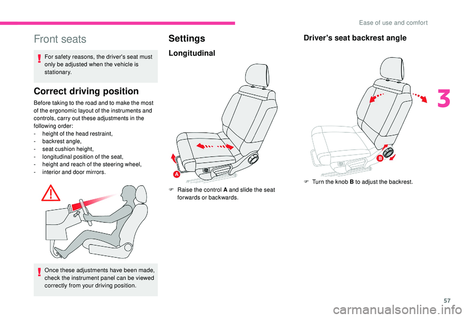
Settings
Longitudinal
F Raise the control A and slide the seat forwards or backwards.
Driver's seat backrest angle
F Turn the knob B to adjust the backrest.
3
Ease of use and comfort
Page 61 of 308
59
Before moving the seat backwards,
ensure that there is nothing that might
prevent the full travel of the seat.
When the front passenger seat is fully
folded, only the outer rear seat behind the
driver can be occupied by a passenger.
Do not place hard, heavy or sharp objects
in the centre of the folded backrest to
ensure that you do not damage rear lining
behind the backrest.
When sharp deceleration occurs, objects
placed on the folded backrest can turn into
dangerous projectiles.Front head restraints
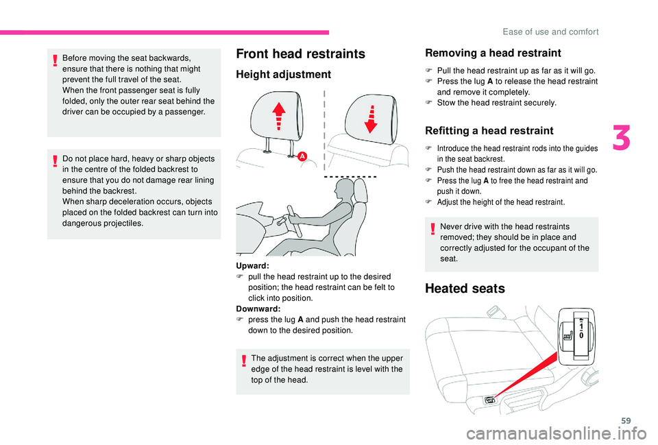
Height adjustment
The adjustment is correct when the upper
edge of the head restraint is level with the
top of the head.
Removing a head restraint
F Pull the head restraint up as far as it will go.
F P ress the lug A to release the head restraint
and remove it completely.
F
S
tow the head restraint securely.
Refitting a head restraint
F Introduce the head restraint rods into the guides in the seat backrest.
F
P
ush the head restraint down as far as it will go.
F
P
ress the lug A to free the head restraint and
push it down.
F
A
djust the height of the head restraint.
Never drive with the head restraints
removed; they should be in place and
correctly adjusted for the occupant of the
seat.
Heated seats
Upward:
F p ull the head restraint up to the desired
position; the head restraint can be felt to
click into position.
Downward:
F
p
ress the lug A and push the head restraint
down to the desired position.
3
Ease of use and comfort
Page 64 of 308
62
Depending on version, if you use the
strap, you do not need to guide backrest 3.
When the backrest is released, the red
indicator is visible in the release grip
(depending on version).
Returning the backrests to
their original position
First check that the outer seat belts are
lying vertically alongside the backrest
latching rings. Caution, a backrest that has not latched
correctly compromises the safety of
passengers in the event of sudden braking
or an accident.
The contents of the boot may be thrown
forward – Risk of serious injury!
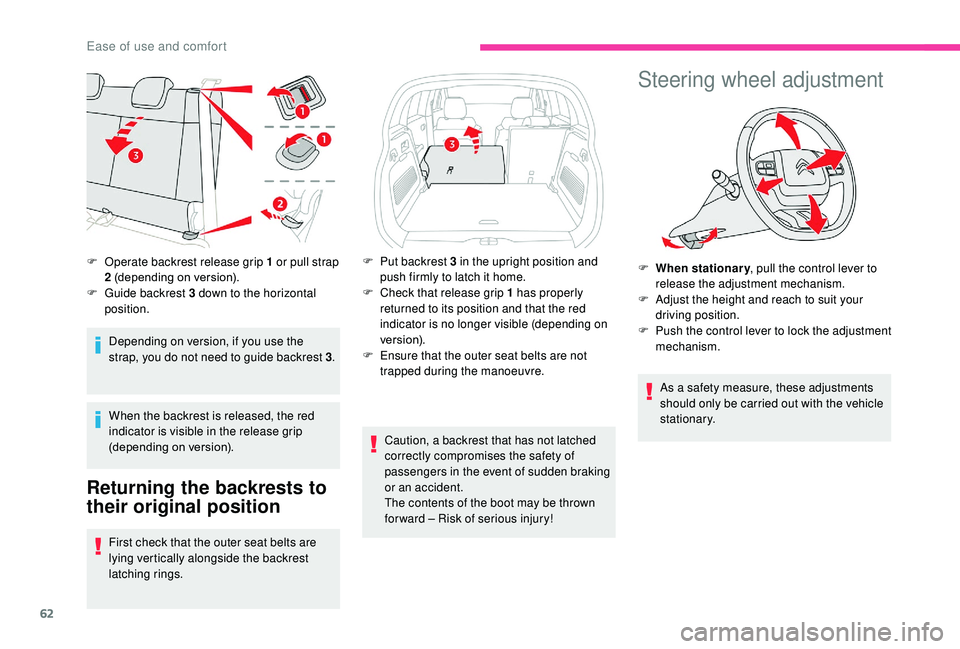
F
O
perate backrest release grip 1 or pull strap
2 (depending on version).
F
G
uide backrest 3 down to the horizontal
position. F
P
ut backrest 3 in the upright position and
push firmly to latch it home.
F
C
heck that release grip 1 has properly
returned to its position and that the red
indicator is no longer visible (depending on
ve r s i o n).
F
E
nsure that the outer seat belts are not
trapped during the manoeuvre.
Steering wheel adjustment
F When stationary , pull the control lever to
release the adjustment mechanism.
F
A
djust the height and reach to suit your
driving position.
F
P
ush the control lever to lock the adjustment
mechanism.
As a safety measure, these adjustments
should only be carried out with the vehicle
stationary.
Ease of use and comfort
Page 76 of 308
74
Front armrest
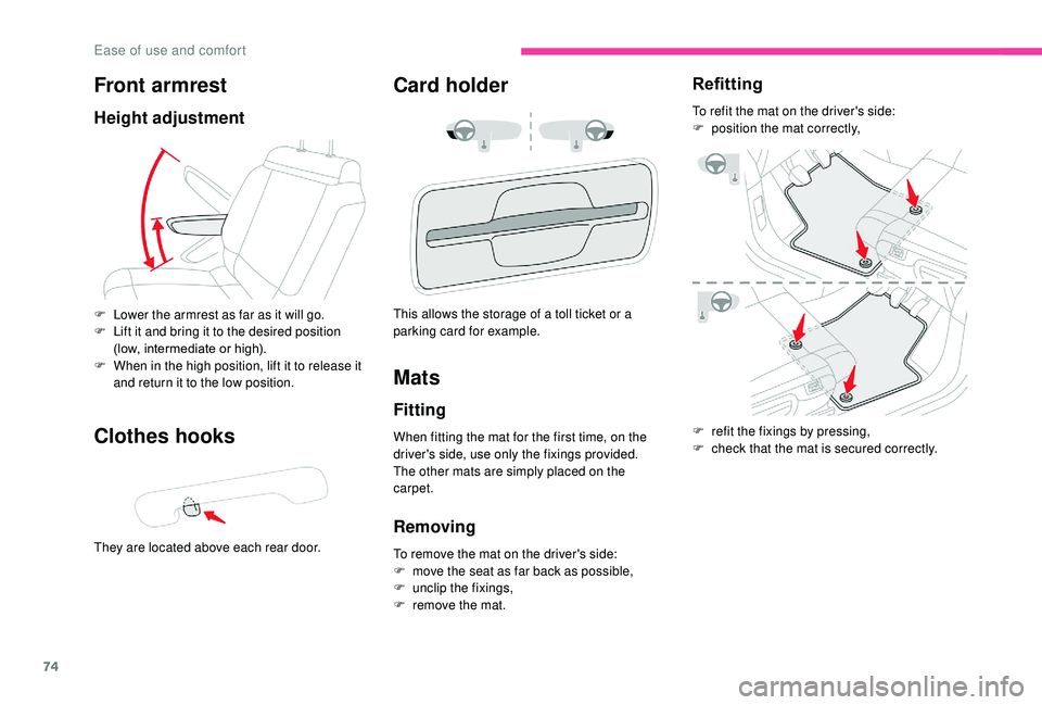
Height adjustment
Clothes hooks
They are located above each rear door.
Card holder
F Lower the armrest as far as it will go.
F L ift it and bring it to the desired position
(low, intermediate or high).
F
W
hen in the high position, lift it to release it
and return it to the low position. This allows the storage of a toll ticket or a
parking card for example.
Mats
Fitting
When fitting the mat for the first time, on the
driver's side, use only the fixings provided.
The other mats are simply placed on the
carpet.
Removing
To remove the mat on the driver's side:
F
m ove the seat as far back as possible,
F
un
clip the fixings,
F
r
emove the mat.
Refitting
To refit the mat on the driver's side:
F p osition the mat correctly,
F
r
efit the fixings by pressing,
F
c
heck that the mat is secured correctly.
Ease of use and comfort
Page 87 of 308

85
The system may suffer inter ference or not
work correctly:
-
u
nder poor visibility conditions (snow,
heavy rain, etc.),
-
i
f the windscreen in front of the camera
is dirty, misted or covered (by a sticker,
e t c .),
-
i
f the vehicle is facing highly reflective
signs.
When the system detects thick fog, it
temporarily deactivates the function.
The system is not able to detect:
-
r
oad users that do not have their own
lighting, such as pedestrians,
-
v
ehicles whose lighting is obscured
(for example, vehicles driving behind a
safety barrier on a motor way),
-
v
ehicles at the top or bottom of a
steep slope, on winding roads, on
crossroads.
Headlamp adjustment
To avoid causing a nuisance to other road
users, the height of the headlamp beams
should be adjusted according to the load in the
vehicle.
0. Driver only or driver + front passenger.
1. Driver + front passenger + rear
passengers + maximum authorised load. The initial setting is position 0.
Cornering lighting
If your vehicle is equipped with it, this system
makes use of the beam from a front foglamp
to illuminate the inside of a bend, when the
main or dipped beam headlamps are on and
the vehicle speed is below 25 mph (40 km/h)
(urban driving, winding road, junctions, parking
manoeuvres, etc.).
Clean the windscreen regularly,
particularly the area in front of the camera.
The internal sur face of the windscreen can
also become misted around the camera.
In humid and cold weather, demist the
windscreen regularly.
Do not allow snow to accumulate on the
bonnet or roof of the vehicle as this could
mask the camera's view.
2.
Driver only + maximum authorised load.
4
Lighting and visibility
Page 100 of 308
98
Switching off
Malfunction
If a fault occurs with the system,
this warning lamp comes on,
accompanied by the display of a
message in the instrument panel.
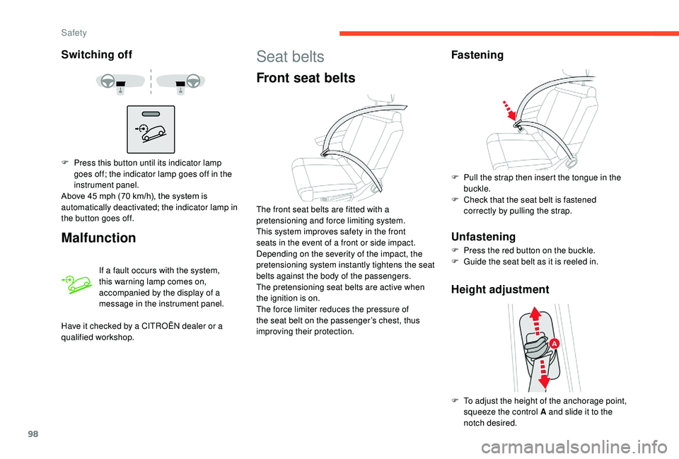
F
P
ress this button until its indicator lamp
goes off; the indicator lamp goes off in the
instrument panel.
Above 45
mph (70 km/h), the system is
automatically deactivated; the indicator lamp in
the button goes off.
Have it checked by a CITROËN dealer or a
qualified workshop.
Seat belts
Front seat belts
The front seat belts are fitted with a
pretensioning and force limiting system.
This system improves safety in the front
seats in the event of a front or side impact.
Depending on the severity of the impact, the
pretensioning system instantly tightens the seat
belts against the body of the passengers.
The pretensioning seat belts are active when
the ignition is on.
The force limiter reduces the pressure of
the seat belt on the passenger’s chest, thus
improving their protection.
Fastening
F Pull the strap then insert the tongue in the buckle.
F
C
heck that the seat belt is fastened
correctly by pulling the strap.
Unfastening
F Press the red button on the buckle.
F G uide the seat belt as it is reeled in.
Height adjustment
F To adjust the height of the anchorage point, squeeze the control A and slide it to the
notch desired.
Safety
Page 121 of 308
119
In case of towing
Driving with a trailer places greater
demands on the towing vehicle and
requires extra care from the driver.
Side wind
F Take into account the increased sensitivity to wind.
Cooling
Towing a trailer on a slope increases the
temperature of the coolant.
As the fan is electrically controlled, its cooling
capacity is not dependent on the engine speed.
F
T
o lower the engine speed, reduce your
speed.
The maximum towable load on an incline
depends on the gradient and the exterior
temperature.
In all cases, keep a check on the coolant
temperature.
Braking
Towing a trailer increases the braking distance.
To avoid overheating of the brakes, the use of
engine braking is recommended.
Ty r e s
F Check the tyre pressures of the towing vehicle and of the trailer, observing the
recommended pressures.
Lighting
F Check the electrical lighting and signalling on the trailer and the headlamp beam height
of your vehicle. If the exterior temperature is high, it is
recommended that the engine be allowed
to idle for 1 to 2
minutes after the vehicle
comes to a stop, to facilitate its cooling.
F
I
f this warning lamp and the
STOP warning lamp come on,
stop the vehicle and switch off
the engine as soon as possible. New vehicle
Do not pull a trailer before having driven at
least 600
miles (1,000 kilometres).
For more information on Headlamp
adjustment , refer to the corresponding
section.
The rear parking sensors will be
deactivated automatically to avoid the
audible signal if a genuine CITROËN
towbar is used.
Anti-theft protection
Electronic immobiliser
The keys contain an electronic chip which has
a secret code. When the ignition is switched
on, this code must be recognised in order for
starting to be possible.
A few seconds after switching off the ignition,
this system locks the engine control system,
therefore preventing the engine from being
started in the event of a break-in.
If the system fails, as reported by a message,
the engine will not start.
Contact a CITROËN dealer.
For safety and theft protection reasons,
never leave your electronic key in the
vehicle, even when you are close to it.
It is recommended that you keep it with
you.
6
Driving
Page 134 of 308
132
Head-up display
System which projects various information onto
a smoked blade in the driver's field of vision so
that they do not have to take their eyes off the
road.
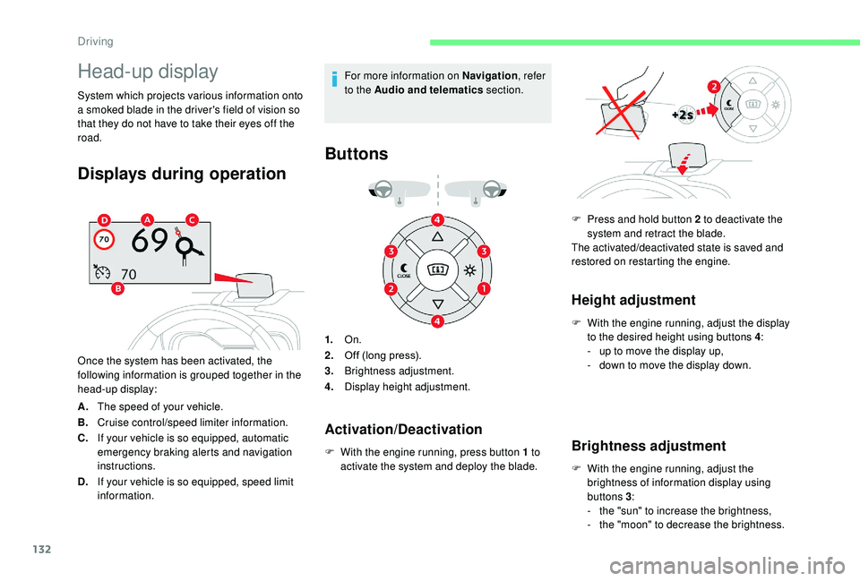
Displays during operation
Once the system has been activated, the
following information is grouped together in the
head-up display:
A.The speed of your vehicle.
B. Cruise control/speed limiter information.
C. If your vehicle is so equipped, automatic
emergency braking alerts and navigation
instructions.
D. If your vehicle is so equipped, speed limit
information. For more information on Navigation
, refer
to the Audio and telematics section.
Buttons
1.On.
2. Off (long press).
3. Brightness adjustment.
4. Display height adjustment.
F
W
ith the engine running, press button 1 to
activate the system and deploy the blade.
Height adjustment
F With the engine running, adjust the display to the desired height using buttons 4 :
-
u
p to move the display up,
-
d
own to move the display down.
Brightness adjustment
F With the engine running, adjust the brightness of information display using
buttons 3 :
-
t
he "sun" to increase the brightness,
-
t
he "moon" to decrease the brightness.
Activation/Deactivation
F Press and hold button 2 to deactivate the system and retract the blade.
The activated/deactivated state is saved and
restored on restarting the engine.
Driving
Page 171 of 308
169
Before each use
Check that the ball joint is correctly fitted,
verifying the follow points:
- the green mark on the star wheel is in
line with the white mark on the towball,
-
t
he star wheel is in contact with the
towball (position A ),
-
t
he security key lock is on and the key
removed; the star wheel can no longer
be operated,
-
t
he towball must not be able to move in
its carrier; test by shaking it with your
hand.
If the towball is not locked, the trailer can
detach – Risk of accident! During use
Never release the locking system with a
trailer or load carrier on the towball.
Never exceed the maximum authorised
weight for the vehicle – the Gross Train
Weight or GTW.
It is essential that the maximum
authorised load be complied with on the
towing device: if it is exceeded, this device
may detach from the vehicle - Risk of
accident!
Check that the trailer lamps work
c o r r e c t l y.
Before setting off, check the adjustment of
the headlamp beam height.
For more information on Headlamp
adjustment
, refer to the corresponding
section.
Following use
When travelling without a trailer or load
on a towbar-mounted carrier, the towball
must be removed and the protective plug
inserted in the carrier. This measure
applies particularly where the towball
might obscure visibility of the number
plate or its lighting.Fitting the towball
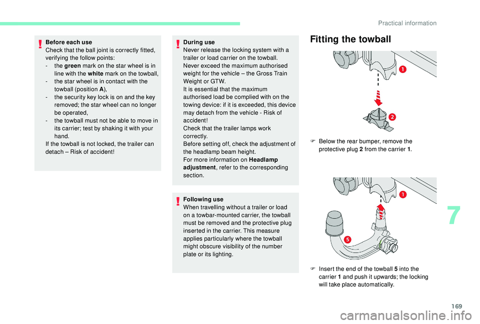
F Below the rear bumper, remove the protective plug 2 from the carrier 1 .
F
I
nsert the end of the towball 5 into the
carrier 1 and push it upwards; the locking
will take place automatically.
7
Practical information