height adjustment CITROEN C3 AIRCROSS 2023 User Guide
[x] Cancel search | Manufacturer: CITROEN, Model Year: 2023, Model line: C3 AIRCROSS, Model: CITROEN C3 AIRCROSS 2023Pages: 244, PDF Size: 7.09 MB
Page 73 of 244

71
Safety
5by a CITROËN dealer or a qualified
workshop.
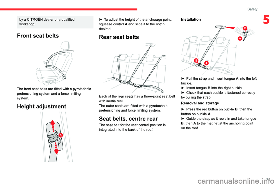
Front seat belts
The front seat belts are fitted with a pyrotechnic
pretensioning system and a force limiting
system.
Height adjustment
► To adjust the height of the anchorage point,
squeeze control A and slide it to the notch
desired.
Rear seat belts
Each of the rear seats has a three-point seat belt
with inertia reel.
The outer seats are fitted with a pyrotechnic
pretensioning and force limiting system.
Seat belts, centre rear
The seat belt for the rear central position is
integrated into the back of the roof.
Installation
► Pull the strap and insert tongue A into the left
buckle.
►
Insert tongue
B into the right buckle.
►
Check that each buckle is fastened correctly
by pulling the strap.
Removal and storage
► Press the red button on buckle B , then the
button on buckle A.
►
Guide the strap as it reels in and take tongue
B
, then A to the magnet at the anchoring point
on the roof.
Page 84 of 244

82
Safety
(b)To install a "rearward facing" child seat at
this seat position, the front passenger airbag
must be deactivated ("OFF").
(c) Only a "forward facing" child seat is
authorised at this seat position with the front
passenger airbag activated (" ON").
(d) Adjust the front passenger seat to the fully
backward position.
(e) To install a "rearward facing" or "forward
facing" child seat on a rear seat, move
the front seat forward, then straighten the
backrest to allow enough space for the child
seat and the child's legs.
(f) To install a "rearward facing" or "forward
facing" child seat on a rear seat, move the
rear seat backwards as far as possible, with
the backrest straightened.
(g) Adjust the seat to the fully backward
position.
(h) Adjust the head restraint to its highest
setting or remove the head restraint.
(i) Depending on version, refer to the
legislation in force in your country before
installing a child in this seat position.
(j) For universal child seat: groups 0, 0+ and 1.
(k) For universal child seat: groups 2 and 3
only. (l)
Seats not fitted with ISOFIX mountings.
(m) Remove the head restraint.
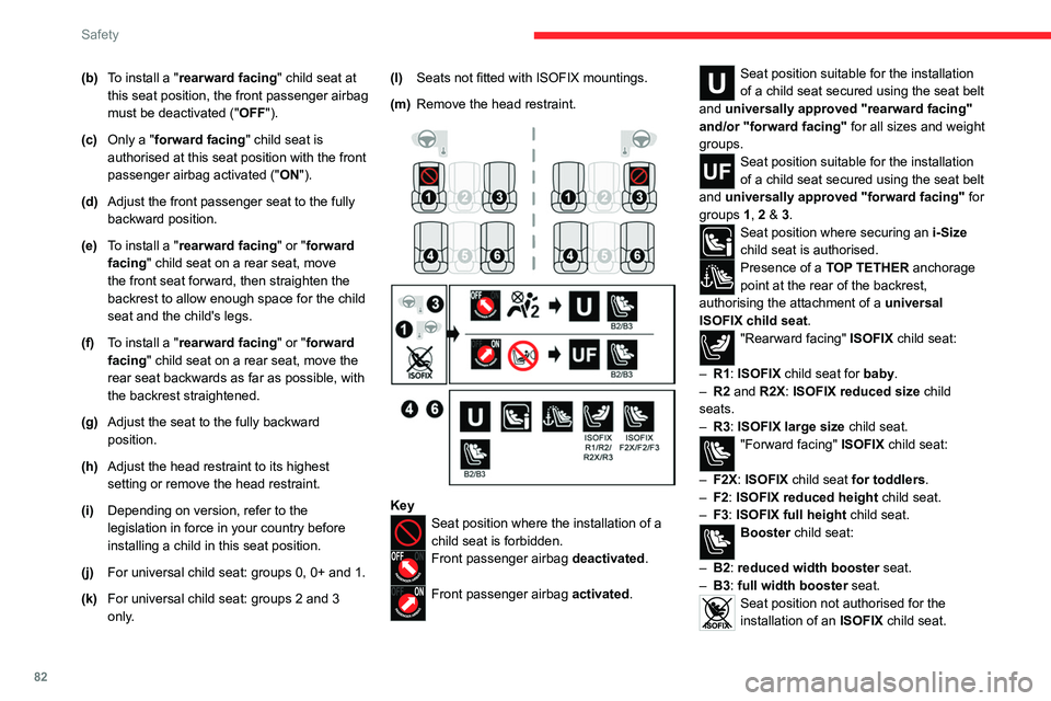
KeySeat position where the installation of a
child seat is forbidden.
Front passenger airbag deactivated.
Front passenger airbag activated.
Seat position suitable for the installation
of a child seat secured using the seat belt
and universally approved "rearward facing"
and/or "forward facing" for all sizes and weight
groups.
Seat position suitable for the installation
of a child seat secured using the seat belt
and universally approved "forward facing" for
groups 1, 2 & 3.
Seat position where securing an i-Size
child seat is authorised.
Presence of a TOP TETHER anchorage
point at the rear of the backrest,
authorising the attachment of a
universal
ISOFIX child seat .
"Rearward facing" ISOFIX child seat:
–
R1
: ISOFIX child seat for baby.
–
R2
and R2X: ISOFIX reduced size child
seats.
–
R3
: ISOFIX large size child seat.
"Forward facing" ISOFIX child seat:
–
F2X
: ISOFIX child seat for toddlers.
–
F2
: ISOFIX reduced height child seat.
–
F3
: ISOFIX full height child seat.
Booster child seat:
–
B2
: reduced width
booster seat.
–
B3
: full width
booster seat.
Seat position not authorised for the
installation of an ISOFIX child seat.
For seat adjustments, refer to the table
"Installing universal, ISOFIX and i-Size child
seats".
Manual child lock
The system prevents a rear door from being
opened using its interior handle.
The red control is located on the edge of
each rear door (indicated by a marking on the
bodywork).
Activation/Deactivation
► To activate the child lock, turn the built-in key
in the red control as far as possible: • To the right on the left-hand rear door.
• To the left on the right-hand rear door.
Page 100 of 244

98
Driving
A front or rear impact to the vehicle can
upset the sensors’ settings, which is not
always detected by the system: distance
measurements may be distorted.
The sensors do not systematically detect
obstacles that are too low (pavements, studs)
or too thin (trees, posts, wire fences).
Certain obstacles located in the sensors’ blind
spots may not be detected or may no longer
be detected during the manoeuvre.
Certain materials (fabrics) absorb sound
waves: pedestrians may not be detected.
Maintenance
Clean the bumpers and door mirrors and
the field of vision of the cameras regularly.
When washing your vehicle at high pressure,
direct the spray from at least 30
cm away
from the sensors and cameras.
Mats/Pedal trims
The use of mats or pedal trims not
approved by CITROËN may interfere with
the operation of the speed limiter or cruise
control.
To avoid any risk of jamming the pedals:
–
Ensure that the mat is secured correctly
.
–
Never fit one mat on top of another
.
Units of speed
Ensure that the units of speed displayed
on the instrument panel (mph or km/h) are
those for the country you are driving in.
If this is not the case, when the vehicle is
stationary, set the display to the required
units of speed so that it complies with what is
authorised locally.
In case of doubt, contact a CITROËN dealer
or a qualified workshop.
Head-up display
System which projects various information onto a
smoked blade placed in the driver's field of vision
to avoid the driver having to take their eyes off
the road.
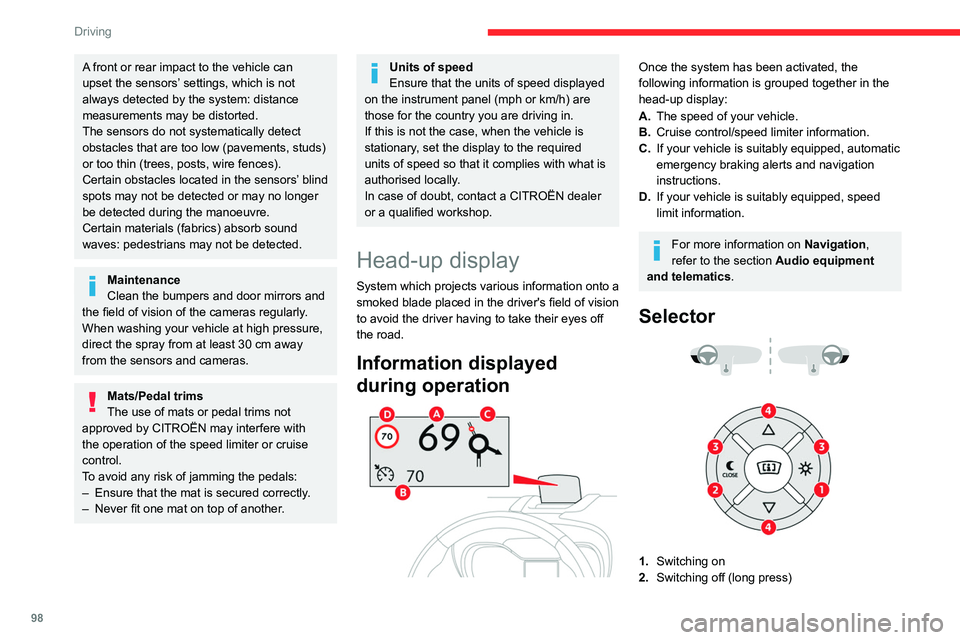
Information displayed
during operation
Once the system has been activated, the
following information is grouped together in the
head-up display:
A. The speed of your vehicle.
B. Cruise control/speed limiter information.
C. If your vehicle is suitably equipped, automatic
emergency braking alerts and navigation
instructions.
D. If your vehicle is suitably equipped, speed
limit information.
For more information on Navigation,
refer to the section Audio equipment
and telematics.
Selector
1. Switching on
2. Switching off (long press)
3.Brightness adjustment
4. Display height adjustment
Activation/Deactivation
► With the engine running, press button 1 to
activate the system and deploy the projection
blade.
► Press and hold button 2 to deactivate the
system and retract the projection blade.
The state of the system is saved when the
engine is switched off and restored on restarting.
Adjusting the height
► With the engine running, adjust the display to
the desired height using the buttons 4:
• up to move the display up,
• down to move the display down.
Page 101 of 244

99
Driving
63.Brightness adjustment
4. Display height adjustment
Activation/Deactivation
► With the engine running, press button 1 to
activate the system and deploy the projection
blade.
► Press and hold button 2 to deactivate the
system and retract the projection blade.
The state of the system is saved when the
engine is switched off and restored on restarting.
Adjusting the height
► With the engine running, adjust the display to
the desired height using the buttons 4
:
•
up to move the display up,
•
down to move the display down.
Brightness adjustment
► With the engine running, adjust the
brightness of the information display using the
buttons
3:
•
on the "sun" to increase the brightness,
•
on the "moon" to decrease the brightness.
When stationary or while driving, no
objects should be placed around the
projection blade (or in its recess) so as not to
impede its movement and correct operation.
In certain extreme weather conditions
(rain and/or snow, bright sunshine, etc.),
the head-up display may not be legible or
may suffer temporary interference.
Some sunglasses may hamper reading of the
information.
To clean the projection blade, use a clean,
soft cloth (such as a spectacles cloth or
microfibre cloth). Do not use a dry or abrasive
cloth, or detergent or solvent products, due to
the risk of scratching the projection blade or
damaging the non-reflective coating.
This system operates when the engine is running, and the settings are saved when
the ignition is switched off.
Memorising speeds
This function, used only for the speed limiter
and programmable cruise control, lets you
save speed settings that will subsequently be
proposed for the purpose of configuring these
two systems.
You can memorise multiple speed settings for
each of the two systems.
By default, some speed settings are already
memorised.
As a safety measure, the driver must only change speed settings when stationary.
Changing a speed setting
Speed settings can be activated,
deactivated, selected and changed in the
Driving
/ Vehicle touch screen menu.
"MEM" button
With this button, you can select a memorised
speed setting to use with the speed limiter or the
programmable cruise control.
Page 126 of 244

124
Practical information
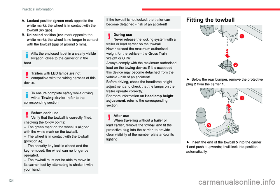
A. Locked position (green mark opposite the white mark); the wheel is in contact with the
towball (no gap).
B. Unlocked position (red mark opposite the white mark); the wheel is no longer in contact
with the towball (gap of around 5
mm).
Affix the enclosed label in a clearly visible location, close to the carrier or in the
boot.
Trailers with LED lamps are not compatible with the wiring harness of this
device.
To ensure complete safety while driving with a Towing device , refer to the
corresponding section.
Before each use
Verify that the towball is correctly fitted,
checking the follow points:
–
The green mark on the wheel is aligned
with the white mark on the towball.
–
The wheel is in contact with the towball
(position A
).
–
The security key lock is closed and the
key removed; the wheel can no longer be
operated.
–
The towball must not be able to move in
its carrier; test by attempting to shake it with
your hand.
If the towball is not locked, the trailer can
become detached - risk of an accident!
During use
Never release the locking system with a
trailer or load carrier on the towball.
Never exceed the maximum authorised
weight for the vehicle - the Gross Train
Weight or GTW.
Always comply with the maximum authorised
load on the towing device: if it is exceeded,
this device may become detached from the
vehicle - risk of an accident!
Before driving, check the headlamp height
adjustment and check that the lamps on the
trailer operate correctly.
For more information on Headlamp height
adjustment, refer to the corresponding
section.
After use
When travelling without a trailer or
load carrier, remove the towball and fit the
protective plug into the carrier, to provide
clear visibility of the number plate and/or its
lighting.
Fitting the towball
► Below the rear bumper , remove the protective
plug 2 from the carrier 1.
► Insert the end of the towball 5 into the carrier
1 and push it upwards; it will lock into position
automatically.