engine Citroen C3 DAG 2010 2.G Owner's Manual
[x] Cancel search | Manufacturer: CITROEN, Model Year: 2010, Model line: C3 DAG, Model: Citroen C3 DAG 2010 2.GPages: 203, PDF Size: 7.66 MB
Page 1 of 203

1
MONITORING
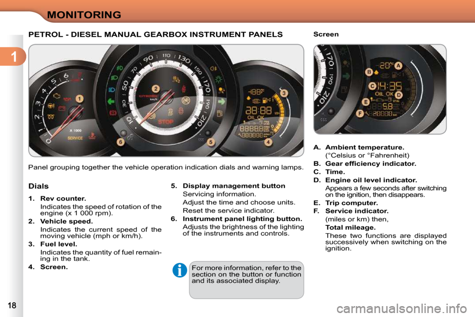
Panel grouping together the vehicle operation indication dials and warning lamps.
PETROL - DIESEL MANUAL GEARBOX INSTRUMENT PANELS
5. Display management button
Servicing information.
Adjust the time and choose units.
Reset the service indicator.
6. Instrument panel lighting button.
Adjusts the brightness of the lighting of the instruments and controls.
For more information, refer to the
section on the button or function
and its associated display.
Dials
1. Rev counter.
Indicates the speed of rotation of the engine (x 1 000 rpm).
2. Vehicle speed.
Indicates the current speed of the moving vehicle (mph or km/h).
3. Fuel level.
Indicates the quantity of fuel remain- ing in the tank.
4. Screen.
A. Ambient temperature.
(°Celsius or °Fahrenheit)
B. Gear
�e�f�fi� �c�i�e�n�c�y
indicator.
C. Time.
D. Engine oil level indicator.
Appears a few seconds after switching on the ignition, then disappears.
E. Trip computer.
F. Service indicato
r.
(miles or km) then,
Total mileage.
These two functions are displayed successively when switching on the
ignition.
Screen
Page 2 of 203

1
MONITORING
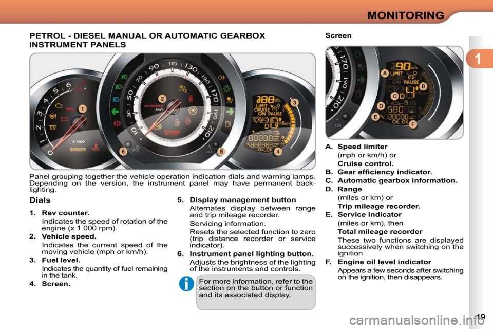
PETROL - DIESEL MANUAL OR AUTOMATIC GEARBOX
INSTRUMENT PANELS
Panel grouping together the vehicle operation indication dials and warning lamps.
Depending on the version, the instrument panel may have perman ent back-
lighting.
Dials
1. Rev counter.
Indicates the speed of rotation of the engine (x 1 000 rpm).
2. Vehicle speed.
Indicates the current speed of the moving vehicle (mph or km/h).
3. Fuel level.
Indicates the quantity of fuel remaining in the tank.
4. Screen.
5. Display management button
Alternates display between range and trip mileage recorder.
Servicing information.
Resets the selected function to zero (trip distance recorder or service
indicator).
6. Instrument panel lighting button.
Adjusts the brightness of the lighting of the instruments and controls.
For more information, refer to the
section on the button or function
and its associated display.
A. Speed limiter
(mph or km/h) or
Cruise control.
B. Gear
�e�f�fi� �c�i�e�n�c�y
indicator.
C. Automatic gearbox information.
D. Range
(miles or km) or
Trip mileage recorder.
E. Service indicator
(miles or km), then
Total mileage recorder
These two functions are displayed successively when switching on the
ignition
F. Engine oil level indicator
Appears a few seconds after switching on the ignition, then disappears.
Screen
Page 3 of 203

1
MONITORING
Indicator and warning lamps
Visual indicators informing the driver that a system is in operat ion (operation or
deactivation indicator lamps) or of the occurrence of a fault (wa rning lamp).
When the ignition is switched on
Certain warning lamps come on for a few seconds when the vehi cle's ignition is
switched on.
When the engine is started, these same warning lamps should switch off.
If they remain on, before moving off, refer to the information on the warning lamp concerned.
Operation indicator lamps
� �I�f� �o�n�e� �o�f� �t�h�e� �f�o�l�l�o�w�i�n�g� �i�n�d�i�c�a�t�o�r� �l�a�m�p�s� �c�o�m�e�s� �o�n�,� �t�h�i�s� �c�o�n�fi� �r�m�s� �t�h�a�t� �t�h�e� �c�o�r�r�e�s�p�o�n�d�i�n�g�
system has come into operation. The warning lamps may come
�o�n� �c�o�n�t�i�n�u�o�u�s�l�y� �(�fi� �x�e�d�)� �o�r� �fl� �a�s�h�.�
Certain warning lamps may
come on in two different modes.
Only by relating the type of light-
ing to the operating status of the
vehicle can it be ascertained
whether the situation is normal
or whether a fault has occurred.
Associated warnings
The switching on of certain warning lamps may be accompanied b y an audible
signal and a message on the multifunction screen.
Warning lamp is on Cause Action/Observations
Left-hand
direction
indicato
r � � �fl� �a�s�h�i�n�g� �w�i�t�h�
buzzer. The lighting stalk is pushed
down.
Right-hand
direction
indicator � � �fl� �a�s�h�i�n�g� �w�i�t�h�
buzzer.
The lighting stalk is pushed up.
Sidelamps � � �fi� �x�e�d�.� � The lighting stalk is in the
"Sidelamps" position. Turn the stalk to the desired position.
Dipped beam
headlamps � � �fi� �x�e�d�.� � The lighting stalk is in the
"Dipped beam headlamps"
position. Turn the stalk to the desired position.
Page 4 of 203

1
MONITORING
Front
foglamps � � �fi� �x�e�d�.� � The front foglamps are
switched on. Turn the ring on the stalk rearwards twice to
switch off the front foglamps.
Rear
foglamps � � �fi� �x�e�d�.� � The rear foglamps are
switched on. Turn the ring on the stalk rearwards to switch off
the rear foglamps.
Diesel engine
pre-heating � � �fi� �x�e�d�.� � The ignition switch is at the
2nd position (ignition on).
Wait until the warning lamp has switched off befor
e starting.
The duration for which the warning lamp is on is
determined by the climatic conditions.
Parking brake � � �fi� �x�e�d�.� � The parking brake is
applied or not properly
released. Release the parking brake to switch off the
warning lamp, keeping your foot on the brake
pedal.
Observe the safety recommendations.
For further information on the parking brake, refer
to the "Driving" section.
Engine
coolant
temperature � � �fi� �x�e�d� �b�l�u�e� � �. On starting the engine, it
indicates that the engine is
cold. After a few minutes driving, it swiches off to
indicate that the engine temperature is normal.
In order to protect your engine, avoid driving too
hard until the warning lamp has switched off.
Foot on the
brake pedal � � �fi� �x�e�d�.� � With an automatic gearbox,
you have forgotten to press
the brake pedal to come out
of the
P postion. With the engine running, before releasing the
parking brake you must press the brake pedal to
unlock the the automatic gear selector lever and
come out of the
P position.
Automatic
wiping � � �fi� �x�e�d�.� � The wiper control is pushed
downwards. Automatic front wiping is activated.
Main beam
headlamps � � �fi� �x�e�d�.� � The lighting stalk is pulled
towards you. Pull the stalk to return to dipped beam
headlamps.
Warning lamp is on Cause Action/Observations
Page 6 of 203

1
MONITORING
Warning lamps
When the engine is running or the vehicle is
being driven, the switching on of one of the fol-
lowing warning lamps indicates a fault which
requires action on the part of the driver.
Any fault resulting in the switching on of a warni ng lamp must be investigated
further by reading the associated message on the mu ltifunction screen.
If you encounter any problems, do not hesitate to contact a CITROËN dealer.
STOP
� � �fi� �x�e�d�,� �a�s�s�o�c�i�a�t�e�d�
with another warning
lamp and
accompanied by
an audible signal.
It is associated with the
braking system or the
engine coolant temperature. Stop as soon as it is safe to do so.
Park, switch off the ignition and call a CITROËN
dealer.
Service temporarily.
A minor fault has occurred
for which there is no
�s�p�e�c�i�fi� �c� �w�a�r�n�i�n�g� �l�a�m�p�.� Identify the fault by reading the message shown
on the screen, such as, for example:
- the engine oil level,
- the screenwash level,
- the remote control battery,
� � �-� � �s�a�t�u�r�a�t�i�o�n� �o�f� �t�h�e� �p�a�r�t�i�c�l�e� �e�m�i�s�s�i�o�n� �fi� �l�t�e�r
(Diesel).
For any other faults, contact a CITROËN dealer.
� � �fi� �x�e�d�.� � A major fault has occurred
for which there is no
�s�p�e�c�i�fi� �c� �w�a�r�n�i�n�g� �l�a�m�p�.� Identify the fault by reading the message shown
on the screen and contact a CITROËN dealer.
Braking � � �fi� �x�e�d�.� �
The braking system
�fl� �u�i�d� �l�e�v�e�l� �h�a�s� �d�r�o�p�p�e�d�
�s�i�g�n�i�fi� �c�a�n�t�l�y�.� � �T�o�p� �u�p� �w�i�t�h� �b�r�a�k�e� �fl� �u�i�d� �r�e�c�o�m�m�e�n�d�e�d� �b�y�
CITROËN.
If the problem persists, have the system checked
by a CITROËN dealer.
+
� � �fi� �x�e�d�,� �a�s�s�o�c�i�a�t�e�d� with the ABS
warning lamp. The electronic brake force
distribution (EBFD) system
has a fault. Have it checked by a CITROËN dealer.
Warning lamp is on Cause Action/Observations
Page 7 of 203

1
MONITORING
Anti-lock
Braking System (ABS) � � �fi� �x�e�d�.� �
The anti-lock braking
system has a fault. The vehicle retains conventional braking.
Drive carefully at reduced speed and contact a
CITROËN dealer without delay.
Dynamic
stability control
(ESP/ASR) � � �fl� �a�s�h�i�n�g�.� �
The ESP/ASR regulation is
active. The system optimises traction and improves the
directional stability of the vehicle.
� � �fi� �x�e�d�.� � Unless it has been
deactivated with the indicator
lamp on the button on, the
ESP/ASR system is faulty. Have it checked by a CITROËN dealer.
Engine
autodiagnosis system � � �fi� �x�e�d�.� �
The emission control
system has a fault.
This lamp should switch off when the engine is star
ted.
If it does not switch off, contact a CITROËN
dealer urgently.
� � �fl� �a�s�h�i�n�g�.� � The engine management
system has a fault. Risk of destruction of the catalytic convertor.
Have it checked by a CITROËN dealer.
Low fuel
level � � �fi� �x�e�d�.� � � �W�h�e�n� �i�t� �fi� �r�s�t� �c�o�m�e�s� �o�n� �t�h�e�r�e�
remains
approximately
5 litres of
fuel in the tank. You must refuel as soon as possible to avoid
running out of fuel.
This warning lamp will come on every time the
�i�g�n�i�t�i�o�n� �i�s� �s�w�i�t�c�h�e�d� �o�n�,� �u�n�t�i�l� �a� �s�u�f�fi� �c�i�e�n�t� �a�d�d�i�t�i�o�n�
of fuel is made.
Fuel tank capacity: approximately 50 litres
(petrol) or 48 litres (Diesel).
Never continue to drive until you run out of fuel
as this could damage the emission control and
injection systems.
Warning lamp is on Cause Action/Observations
Page 8 of 203

1
MONITORING
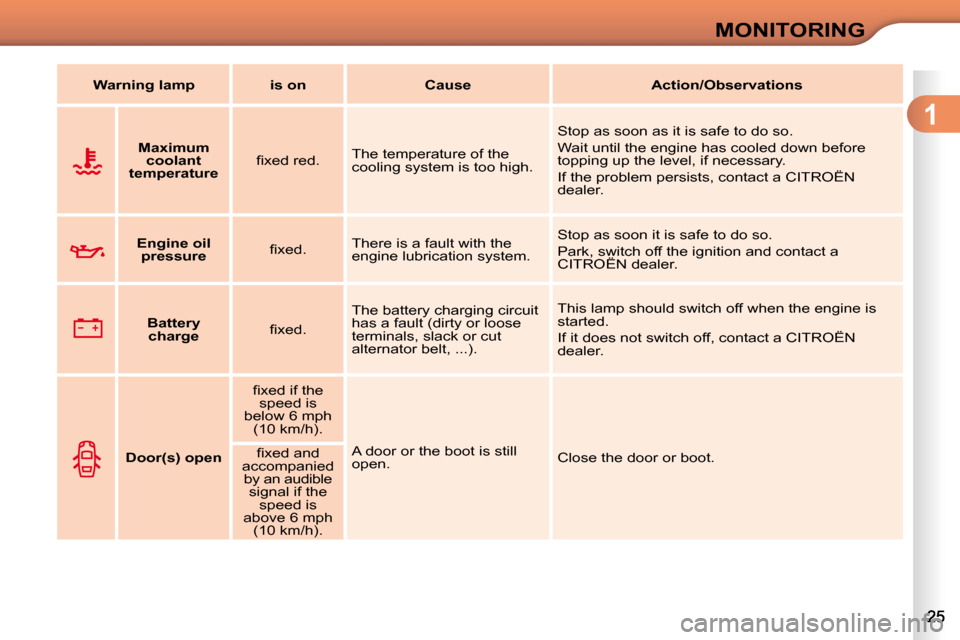
Maximum
coolant
temperature � � �fi� �x�e�d� �r�e�d�.� �
The temperature of the
cooling system is too high. Stop as soon as it is safe to do so.
Wait until the engine has cooled down before
topping up the level, if necessary.
If the problem persists, contact a CITROËN
dealer.
Engine oil
pressure � � �fi� �x�e�d�.� � There is a fault with the
engine lubrication system. Stop as soon it is safe to do so.
Park, switch off the ignition and contact a
CITROËN dealer.
Battery
charge � � �fi� �x�e�d�.� � The battery charging circuit
has a fault (dirty or loose
terminals, slack or cut
alternator belt, ...). This lamp should switch off when the engine is
started.
If it does not switch off, contact a CITROËN
dealer.
Door(s) open � � �fi� �x�e�d� �i�f� �t�h�e�
speed is
below 6 mph (10 km/h).
A door or the boot is still
open. Close the door or boot.
� � �fi� �x�e�d� �a�n�d
accompanied by an audible signal if the speed is
above 6 mph (10 km/h).
Warning lamp is on Cause Action/Observations
Page 9 of 203

1
MONITORING
Airbags temporarily.
This lamp comes on for
a few seconds when you
turn on the ignition, then
switches off. This lamp should switch off when the engine is
started.
If it does not switch off, contact a CITROËN
dealer.
� � �fi� �x�e�d�.� � One of the airbag or seat
belt pretensioner systems
has a fault. Have it checked by a CITROËN dealer.
Seat belt not
fastened/
unfastened � � �fi� �x�e�d� �t�h�e�n�
�fl� �a�s�h�i�n�g�
accompanied by an
increasing
audible signal. The driver and/or the front
passenger has not fastened
or has unfastened their seat
belt.
Pull the strap then insert the tongue in the
buckle.
Water in
Diesel � � �fi� �x�e�d�.� � � �T�h�e� �d�i�e�s�e�l� �fi� �l�t�e�r� �c�o�n�t�a�i�n�s�
water. Risk of damage to the injection system on Diesel
engines.
Contact a CITROËN dealer without delay.
Power
steering � �fi� �x�e�d�.� The power steering has a
fault. Drive carefully at reduced speed.
Have it checked by a CITROËN dealer.
+
Particle
emissions
�fi� �l�t�e�r� �(�D�i�e�s�e�l�)
� �fi� �x�e�d�,� �a�s�s�o�c�i�a�t�e�d�
temporarily with lighting of the
service warning lamp. This indicates that the
�p�a�r�t�i�c�l�e� �e�m�i�s�s�i�o�n�s� �fi� �l�t�e�r� �i�s�
starting to become
saturated. As soon as driving conditions allow, regenerate
�t�h�e� �fi� �l�t�e�r� �b�y� �d�r�i�v�i�n�g� �a�t� �a� �s�p�e�e�d� �o�f� �a�t� �l�e�a�s�t� �3�5� �m�p�h
�
(60 km/h) until the service warning lamp switches o ff.
� �fi� �x�e�d�,� �a�s�s�o�c�i�a�t�e�d�
temporarily with
lighting of the service warning lamp. This indicates the minimum
level for the Diesel fuel
additive reservoir. Have the reservoir topped up as soon as possible
by a CITROËN dealer.
Warning lamp is on Cause Action/Observations
Page 13 of 203

1
MONITORING
The level read will only be cor-
rect if the vehicle is on level
ground and the engine has been
off for more than 15 minutes.
Engine oil level indicator
System which informs the driver whether
the engine oil level is correct or not.
This information is indicated for a few
seconds when the ignition is switched
on, after the service information.
Oil level correct
� �T�h�i�s� �i�s� �i�n�d�i�c�a�t�e�d� �b�y� �t�h�e� �fl� �a�s�h�i�n�g� �o�f� �
"OIL" ,
linked with the service warning lamp, ac-
companied by an audible signal and a
message on the multifunction screen.
� �I�f� �t�h�e� �l�a�c�k� �o�f� �o�i�l� �i�s� �c�o�n�fi� �r�m�e�d� �b�y� �a� �c�h�e�c�k�
using the dipstick, it is essential that the
level is topped up to prevent damage to
the engine.
Lack of oil
� �T�h�i�s� �i�s� �i�n�d�i�c�a�t�e�d� �b�y� �t�h�e� �fl� �a�s�h�i�n�g� �o�f�
"OIL
--" . Consult a CITROËN dealer.
Oil level indicator fault
Dipstick
There are 2 marks on the
dipstick:
- A = max; never exceed
this level (risk of dam-
age to the engine),
- B = min; top up the level
�v�i�a� �t�h�e� �o�i�l� �fi� �l�l�e�r� �c�a�p�,� �u�s�i�n�g�
the grade of oil suited to
your engine.
Refer to the "Checks" section to locate
�t�h�e� �d�i�p�s�t�i�c�k� �a�n�d� �t�h�e� �o�i�l� �fi� �l�l�e�r� �c�a�p� �o�n� �y�o�u�r�
engine.
Page 38 of 203

3
COMFORT
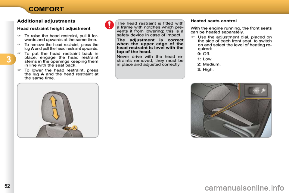
Additional adjustments
Head restraint height adjustment
� � � �T�o� �r�a�i�s�e� �t�h�e� �h�e�a�d� �r�e�s�t�r�a�i�n�t�,� �p�u�l�l� �i�t� �f�o�r�-
�w�a�r�d�s� �a�n�d� �u�p�w�a�r�d�s� �a�t� �t�h�e� �s�a�m�e� �t�i�m�e�.�
�
�T�o� �r�e�m�o�v�e� �t�h�e� �h�e�a�d� �r�e�s�t�r�a�i�n�t�,� �p�r�e�s�s� �t�h�e�
lug A� � �a�n�d� �p�u�l�l� �t�h�e� �h�e�a�d� �r�e�s�t�r�a�i�n�t� �u�p�w�a�r�d�s�.�
� � � �T�o� �p�u�t� �t�h�e� �h�e�a�d� �r�e�s�t�r�a�i�n�t� �b�a�c�k� �i�n�
�p�l�a�c�e�,� �e�n�g�a�g�e� �t�h�e� �h�e�a�d� �r�e�s�t�r�a�i�n�t�
stems in the openings keeping them
�i�n� �l�i�n�e� �w�i�t�h� �t�h�e� �s�e�a�t� �b�a�c�k�.�
� � � �T�o� �l�o�w�e�r� �t�h�e� �h�e�a�d� �r�e�s�t�r�a�i�n�t�,� �p�r�e�s�s�
the lug A� � �a�n�d� �t�h�e� �h�e�a�d� �r�e�s�t�r�a�i�n�t� �a�t�
�t�h�e� �s�a�m�e� �t�i�m�e�.� � Heated seats control
With the engine running, the front seats
�c�a�n� �b�e� �h�e�a�t�e�d� �s�e�p�a�r�a�t�e�l�y�.�
� � � �U�s�e� �t�h�e� �a�d�j�u�s�t�m�e�n�t� �d�i�a�l�,� �p�l�a�c�e�d� �o�n�
�t�h�e� �s�i�d�e� �o�f� �e�a�c�h� �f�r�o�n�t� �s�e�a�t�,� �t�o� �s�w�i�t�c�h�
�o�n� �a�n�d� �s�e�l�e�c�t� �t�h�e� �l�e�v�e�l� �o�f� �h�e�a�t�i�n�g� �r�e�-
�q�u�i�r�e�d�:� �
0: � � � � �O�f�f�.�
1
: � � �L�o�w�.�
2
: � � �M�e�d�i�u�m�.�
3
: � � �H�i�g�h�.� � �
� �T�h�e� �h�e�a�d� �r�e�s�t�r�a�i�n�t� �i�s� �fi� �t�t�e�d� �w�i�t�h�
a frame with notches which pre-
�v�e�n�t�s� �i�t� �f�r�o�m� �l�o�w�e�r�i�n�g�;� �t�h�i�s� �i�s� �a�
�s�a�f�e�t�y� �d�e�v�i�c�e� �i�n� �c�a�s�e� �o�f� �i�m�p�a�c�t�.�
The adjustment is correct
when the upper edge of the
head restraint is level with the
top of the head.
� �N�e�v�e�r� �d�r�i�v�e� �w�i�t�h� �t�h�e� �h�e�a�d� �r�e�-
�s�t�r�a�i�n�t�s� �r�e�m�o�v�e�d�;� �t�h�e�y� �m�u�s�t� �b�e�
�i�n� �p�l�a�c�e� �a�n�d� �a�d�j�u�s�t�e�d� �c�o�r�r�e�c�t�l�y�.� � �