tow Citroen C3 PICASSO RHD 2014 1.G Owner's Guide
[x] Cancel search | Manufacturer: CITROEN, Model Year: 2014, Model line: C3 PICASSO RHD, Model: Citroen C3 PICASSO RHD 2014 1.GPages: 288, PDF Size: 8.38 MB
Page 150 of 288
148
Parking brake
If excessive travel or a loss of
effectiveness of this system is
noticed, the parking brake must be
checked, even between two services.
Manual gearbox
The gearbox does not require any
maintenance (no oil change).
Refer to the maintenance and
warranty guide for the checking
interval for this component.For information on checking brake
disc wear, contact a CITROËN dealer
or a qualified workshop.
Brake disc wear
Brake wear depends on the style
of driving, particularly in the case
of vehicles used in town, over short
distances. It may be necessary to have
the condition of the brakes checked,
even between vehicle services.
Brake pads
The gearbox does not require any
maintenance (no oil change).
Refer to the maintenance and
warranty guide for details of the
checking interval for this component.
Electronic gearboxonly use products recommended by
CITRoËn or products of equivalent
quality and specification.
In order to optimise the operation of
units as important as those in the
braking system, CITR
oËn
selects and
offers very specific products.
After washing the vehicle, dampness,
or in wintry conditions, ice can form
on the brake discs and pads: braking
efficiency may be reduced. Make light
brake applications to dry and defrost
the brakes.
Checking this system must be done by a
CITROËN dealer or a qualified workshop.
Unless there is a leak in the circuit, a drop in
the brake fluid level indicates that the brake
pads are worn.
Checks
Page 152 of 288

150
F Switch off the ignition.
F S ecure the speed limit sticker inside the
vehicle. F
U ncoil the pipe stowed under the
compressor.
F
C
onnect the pipe from the compressor to
the sealant cartridge.
F
T
urn the the sealant cartridge and secure it
in the cut-out provided on the compressor.
av
oid removing any foreign bodies
which have penetrated into the tyre. F
R emove the valve cap from the tyre to be
repaired, and place it in a clean area.
F
C
onnect the hose from the sealant
cartridge to the valve of the tyre to be
repaired and tighten firmly.
Repair procedure
Practical information
Page 153 of 288
151
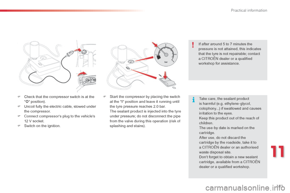
F Check that the compressor switch is at the "O " position).
F
U
ncoil fully the electric cable, stowed under
the compressor.
F
C
onnect compressor's plug to the vehicle's
12 V socket.
F
S
witch on the ignition. Take care, the sealant product
is harmful (e.g. ethylene-glycol,
colophony...) if swallowed and causes
irritation to the eyes.
ke
ep this product out of the reach of
children.
The use-by date is marked on the
cartridge.
af
ter use, do not discard the
cartridge by the roadside, take it to
a CITR
oËn
dealer or an authorised
waste disposal site.
Don't forget to obtain a new sealant
cartridge, available from a CITR
oËn
dealer or a qualified workshop.
F
S tart the compressor by placing the switch
at the " I" position and leave it running until
the tyre pressure reaches 2.0 bar.
T
he sealant product is injected into the tyre
under pressure; do not disconnect the pipe
from the valve during this operation (risk of
splashing and stains). If after around 5 to 7 minutes the
pressure is not attained, this indicates
that the tyre is not repairable; contact
a CITR
oËn
dealer or a qualified
workshop for assistance.
11
Practical information
Page 154 of 288
152
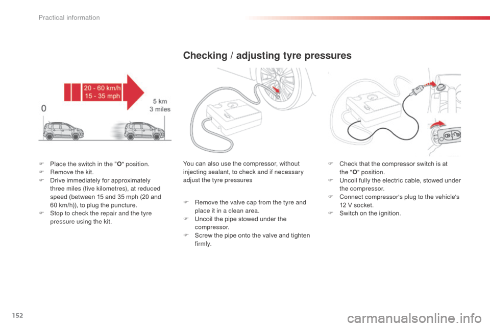
F Place the switch in the "O" position.
F R emove the kit.
F
D
rive immediately for approximately
three miles (five kilometres), at reduced
speed (between 15 and 35 mph (20 and
60
km/h)), to plug the puncture.
F
S
top to check the repair and the tyre
pressure using the kit.
Checking / adjusting tyre pressures
You can also use the compressor, without
injecting sealant, to check and if necessary
adjust the tyre pressures
F
R
emove the valve cap from the tyre and
place it in a clean area.
F
U
ncoil the pipe stowed under the
compressor.
F
S
crew the pipe onto the valve and tighten
f i r m l y. F
C heck that the compressor switch is at
the
"O " position.
F
U
ncoil fully the electric cable, stowed under
the compressor.
F
C
onnect compressor's plug to the vehicle's
12 V socket.
F
S
witch on the ignition.
Practical information
Page 155 of 288

153
F Start the compressor by placing the switch at the " I" position and adjust the pressure
to the value shown on the vehicle's tyre
pressure label.
T
o deflate: press the black button on the
compressor pipe, at the valve connector.
F
o
n
ce the correct pressure is reached, put
the switch to the " O" position.
F
R
emove the kit then stow it.
Tyre under-inflation detection
After repair of the tyre, the warning
lamp will remain on until the system is
reinitialised.
For more information, refer to the
"Under-inflation detection" section.
Should the pressure of one or more
tyres be adjusted, it is necessary to
reinitialise the under-inflation detection
system.
Refer to the "Under-inflation detection"
section.
11
Practical information
Page 156 of 288
154
Changing a wheel
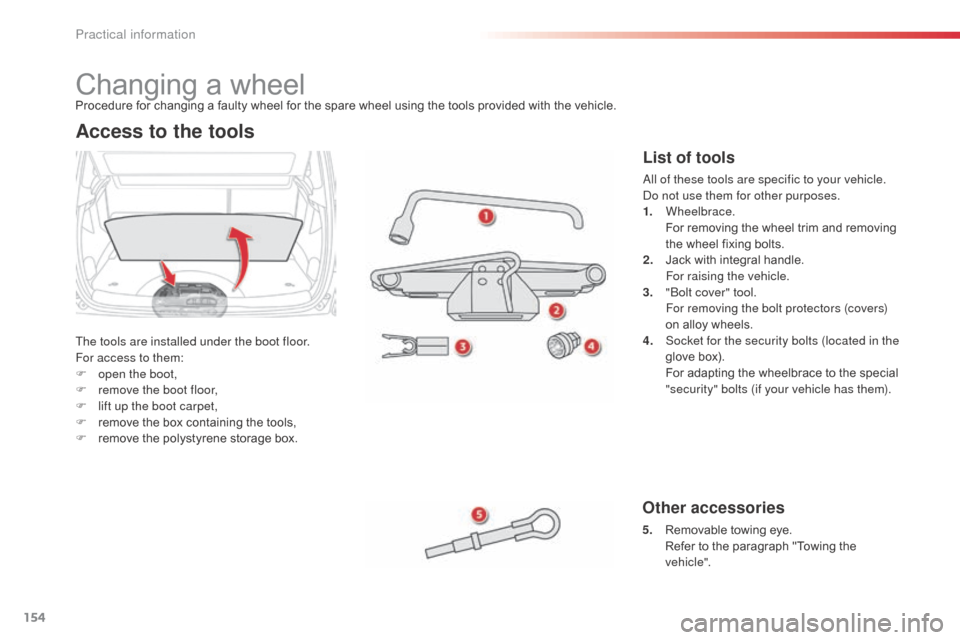
The tools are installed under the boot floor.
For access to them:
F
o
pen the boot,
F
r
emove the boot floor,
F
l
ift up the boot carpet,
F
r
emove the box containing the tools,
F
r
emove the polystyrene storage box.
Other accessories
5. Removable towing eye. R efer to the paragraph "Towing the
vehicle".
Access to the tools
Procedure for changing a faulty wheel for the spare wheel using the tools provided with the vehicle.
List of tools
all of these tools are specific to your vehicle. do n ot use them for other purposes.
1.
Wheelbrace.
F
or removing the wheel trim and removing
the wheel fixing bolts.
2.
J
ack with integral handle.
F
or raising the vehicle.
3.
"bo
lt cover" tool.
F
or removing the bolt protectors (covers)
on alloy wheels.
4.
S
ocket for the security bolts (located in the
glove box).
F
or adapting the wheelbrace to the special
"security" bolts (if your vehicle has them).
Practical information
Page 158 of 288
156
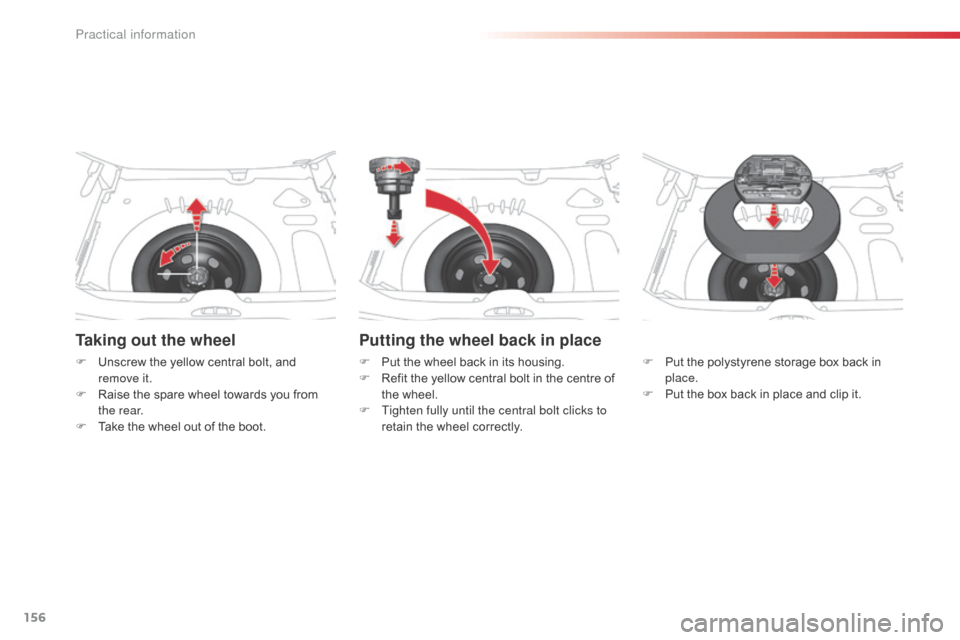
Taking out the wheel
F Unscrew the yellow central bolt, and remove it.
F
R
aise the spare wheel towards you from
the rear.
F
T
ake the wheel out of the boot.
Putting the wheel back in place
F Put the wheel back in its housing.
F R efit the yellow central bolt in the centre of
the wheel.
F
T
ighten fully until the central bolt clicks to
retain the wheel correctly. F
P ut the polystyrene storage box back in
place.
F
P
ut the box back in place and clip it.
Practical information
Page 164 of 288
162
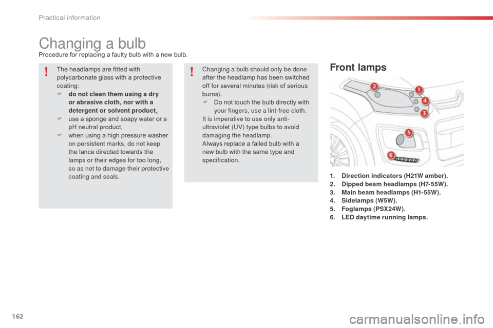
Changing a bulbProcedure for replacing a faulty bulb with a new bulb.1.
D
irection indicators (H21W amber).
2.
D
ipped beam headlamps (H7-55W).
3.
M
ain beam headlamps (H1-55W).
4.
S
idelamps (W5W).
5.
F
oglamps (PSX24W).
6.
L
ED daytime running lamps.
Front lampsThe headlamps are fitted with
polycarbonate glass with a protective
coating:
F
d
o not clean them using a dr y
or abrasive cloth, nor with a
detergent or solvent product,
F
u
se a sponge and soapy water or a
pH neutral product,
F
w
hen using a high pressure washer
on persistent marks, do not keep
the lance directed towards the
lamps or their edges for too long,
so as not to damage their protective
coating and seals. Changing a bulb should only be done
after the headlamp has been switched
off for several minutes (risk of serious
burns).
F
D
o not touch the bulb directly with
your fingers, use a lint-free cloth.
It is imperative to use only anti-
ultraviolet (UV) type bulbs to avoid
damaging the headlamp.
Always replace a failed bulb with a
new bulb with the same type and
specification.
Practical information
Page 167 of 288
165
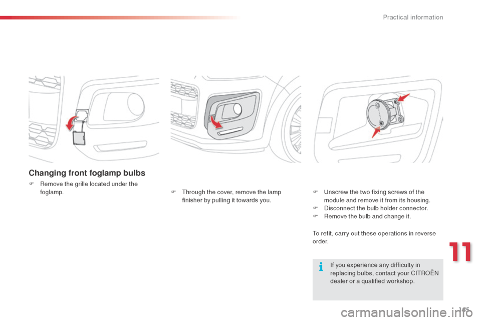
Changing front foglamp bulbs
F Remove the grille located under the foglamp.
If you experience any difficulty in
replacing bulbs, contact your CITR
oËn
dealer or a qualified workshop.
F
T
hrough the cover, remove the lamp
finisher by pulling it towards you. F
U
nscrew the two fixing screws of the
module and remove it from its housing.
F
d
i
sconnect the bulb holder connector.
F
R
emove the bulb and change it.
To refit, carry out these operations in reverse
o r d e r.
11
Practical information
Page 185 of 288
183
Towing the vehicle
Access to the tools
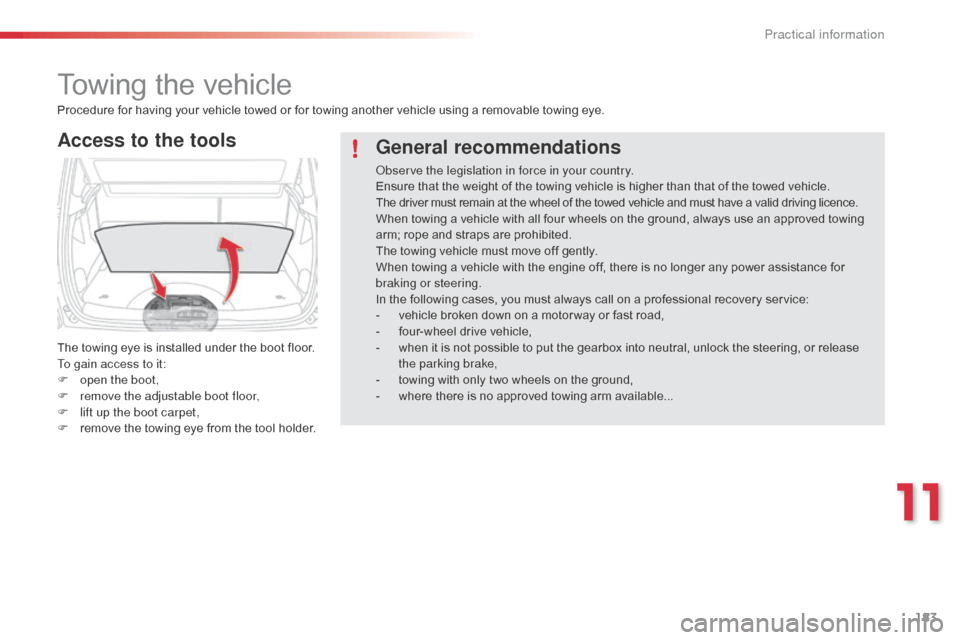
The towing eye is installed under the boot floor.
To gain access to it:
F
o
pen the boot,
F
r
emove the adjustable boot floor,
F
l
ift up the boot carpet,
F
r
emove the towing eye from the tool holder.
Procedure for having your vehicle towed or for towing another vehicle using a removable towing eye.
General recommendations
observe the legislation in force in your country.
Ensure that the weight of the towing vehicle is higher than that of the towed vehicle.
The driver must remain at the wheel of the towed vehicle and must have a valid driving licence.
When towing a vehicle with all four wheels on the ground, always use an approved towing
arm; rope and straps are prohibited.
The towing vehicle must move off gently.
When towing a vehicle with the engine off, there is no longer any power assistance for
braking or steering.
In the following cases, you must always call on a professional recovery service:
-
v
ehicle broken down on a motor way or fast road,
-
f
our-wheel drive vehicle,
-
w
hen it is not possible to put the gearbox into neutral, unlock the steering, or release
the parking brake,
-
t
owing with only two wheels on the ground,
-
w
here there is no approved towing arm available...
11
Practical information