hub Citroen C4 2005 2.G User Guide
[x] Cancel search | Manufacturer: CITROEN, Model Year: 2005, Model line: C4, Model: Citroen C4 2005 2.GPages: 462, PDF Size: 10.48 MB
Page 265 of 462
![Citroen C4 2005 2.G User Guide Downloaded from www.Manualslib.com manuals search engine 259
ENGINE
CHECKING AND SETTING THE VALVE TIMING
Engine: WJY
Tools.
[1]Pliers for remving plastic pins: 7504-T or (-).1311
[2]Flywheel peg: 701 Citroen C4 2005 2.G User Guide Downloaded from www.Manualslib.com manuals search engine 259
ENGINE
CHECKING AND SETTING THE VALVE TIMING
Engine: WJY
Tools.
[1]Pliers for remving plastic pins: 7504-T or (-).1311
[2]Flywheel peg: 701](/img/9/4138/w960_4138-264.png)
Downloaded from www.Manualslib.com manuals search engine 259
ENGINE
CHECKING AND SETTING THE VALVE TIMING
Engine: WJY
Tools.
[1]Pliers for remving plastic pins: 7504-T or (-).1311
[2]Flywheel peg: 7014-T.J or (-).0188 Y
[3]Injection pump setting peg Ø 6 mm : (-).0188 H
[4]Screw H M8 : (-).0188 E
[5]Belt retaining pin: (-).0188 K
[6] Square for adjusting belt tension: (-).0188 J1
[7] Belt tension measuring instrument, with digital display: SEEM CTG 105.5M
Checking the timing.
Peg the flywheel, using tool [2].
Peg the camshaft hub, using tool [4].
Peg the injection pump hub, using tool[3].
IMPERATIVE: If the pegging proves impossible, repeat the setting of the timing.
B1BP2FTC
B1EP16PD
XSARA
Angl.-t2-page240-282-2005 9/01/06 10:16 Page 259
Page 267 of 462
![Citroen C4 2005 2.G User Guide Downloaded from www.Manualslib.com manuals search engine 261
ENGINE
CHECKING AND SETTING THE VALVE TIMING
Engine: WJY
Setting the timing (continued).
Peg the camshaft hub, using tool[4].
Peg the injec Citroen C4 2005 2.G User Guide Downloaded from www.Manualslib.com manuals search engine 261
ENGINE
CHECKING AND SETTING THE VALVE TIMING
Engine: WJY
Setting the timing (continued).
Peg the camshaft hub, using tool[4].
Peg the injec](/img/9/4138/w960_4138-266.png)
Downloaded from www.Manualslib.com manuals search engine 261
ENGINE
CHECKING AND SETTING THE VALVE TIMING
Engine: WJY
Setting the timing (continued).
Peg the camshaft hub, using tool[4].
Peg the injection pump hub, using tool[3].
Slacken screws (5)and (6).
Slacken screw (9)of the tensioner roller (8).
Remove the timing belt.
Refitting.
Retighten screws (5)and (6) by hand.
Turn the pinions (10)and(7)clockwise in order to place them at end of slots.
Fit the timing belt on the crankshaft.
Hold the belt, using tool [5].
Position the timing belt in the following sequence:
- Guide roller (11).
- Injection pump pinion (7).
- Camshaft pinion (10).
- Coolant pump pinion (12).
- Tensioner roller (8).
B1EP16PDB1EP1EDCB1EP132C
XSARA
B1EP1EEC
Angl.-t2-page240-282-2005 9/01/06 10:16 Page 261
Page 268 of 462
Downloaded from www.Manualslib.com manuals search engine 262
ENGINECHECKING AND SETTING THE VALVE TIMING
Engine: WJY
B1EP1EDC
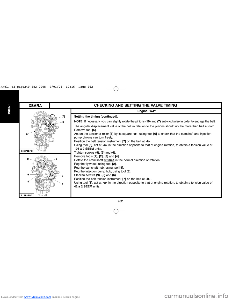
Setting the timing (continued).
NOTE:If necessary, you can slightly rotate the pinions (10)and (7)anti-clockwise in order to engage the belt.
The angular displacement value of the belt in relation to the pinions should not be more than half a tooth.
Remove tool [5].
Act on the tensioner roller (8)by its square «a», using tool [6]to check that the camshaft and injection
pump pinions can turn freely.
Position the belt tension instrument [7]on the belt at «b».
Using tool [6], act at «a»in the direction opposite to that of engine rotation, to obtain a tension value of
106 ± 2 SEEMunits.
Tighten screws (9), (5) and (6).
Remove tools [7], [2], [3]and [4].
Rotate the crankshaft 8 times
in the normal direction of rotation.
Peg the flywheel, using tool [2].
Peg the camshaft hub, using tool [4].
Peg the injection pump hub, using tool [3].
Slacken screws (9), (5)and (6).
Position the belt tension instrument [7]on the belt at «b».
Using tool [6], act at «a»in the direction opposite to that of engine rotation, to obtain a tension value of
42 ± 2 SEEMunits.
B1EP1EFC
XSARA
Angl.-t2-page240-282-2005 9/01/06 10:16 Page 262
Page 269 of 462
Downloaded from www.Manualslib.com manuals search engine 263
ENGINE
CHECKING AND SETTING THE VALVE TIMING
Engine: WJY
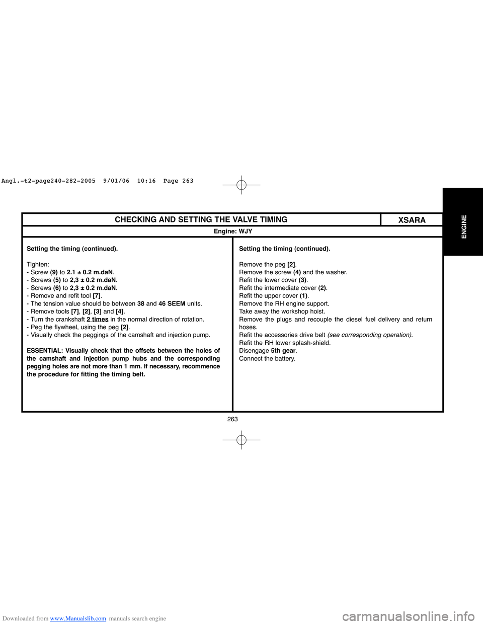
Setting the timing (continued).
Tighten:
- Screw (9)to 2.1 ± 0.2 m.daN.
- Screws (5)to 2,3 ± 0.2 m.daN.
- Screws (6)to 2,3 ± 0.2 m.daN.
- Remove and refit tool [7].
- The tension value should be between 38 and 46 SEEMunits.
- Remove tools [7], [2], [3]and [4].
- Turn the crankshaft 2 times
in the normal direction of rotation.
- Peg the flywheel, using the peg [2].
- Visually check the peggings of the camshaft and injection pump.
ESSENTIAL: Visually check that the offsets between the holes of
the camshaft and injection pump hubs and the corresponding
pegging holes are not more than 1 mm. If necessary, recommence
the procedure for fitting the timing belt.
XSARA
Setting the timing (continued).
Remove the peg [2].
Remove the screw (4)and the washer.
Refit the lower cover (3).
Refit the intermediate cover (2).
Refit the upper cover (1).
Remove the RH engine support.
Take away the workshop hoist.
Remove the plugs and recouple the diesel fuel delivery and return
hoses.
Refit the accessories drive belt
(see corresponding operation).
Refit the RH lower splash-shield.
Disengage 5th gear.
Connect the battery.
Angl.-t2-page240-282-2005 9/01/06 10:16 Page 263
Page 313 of 462
Downloaded from www.Manualslib.com manuals search engine 307
CLUTCH
GEARBOX
TRANSMISSION
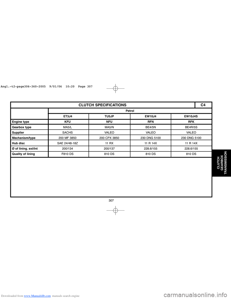
CLUTCH SPECIFICATIONS
Engine type KFU NFU RFN RFK
Gearbox type MA5/L MA5/N BE4/5N BE4R/5S
SupplierSACHS VALEO VALEO VALEO
Mechanism/type200 MF 3850 200 CPX 3850 230 DNG 5100 230 DNG 5100
Hub discSAE 24/48-18Z 11 RX 11 R 14X 11 R 14X
Ø of lining. ext/int200/134 200/137 228.6/155 228.6/155
Quality of liningF810 DS 810 DS 810 DS 810 DS
ET3J4 TU5JP EW10J4 EW10J4S
Petrol
C4
Angl.-t2-page306-360-2005 9/01/06 10:20 Page 307
Page 314 of 462
Downloaded from www.Manualslib.com manuals search engine 308
CLUTCH
GEARBOX
TRANSMISSION
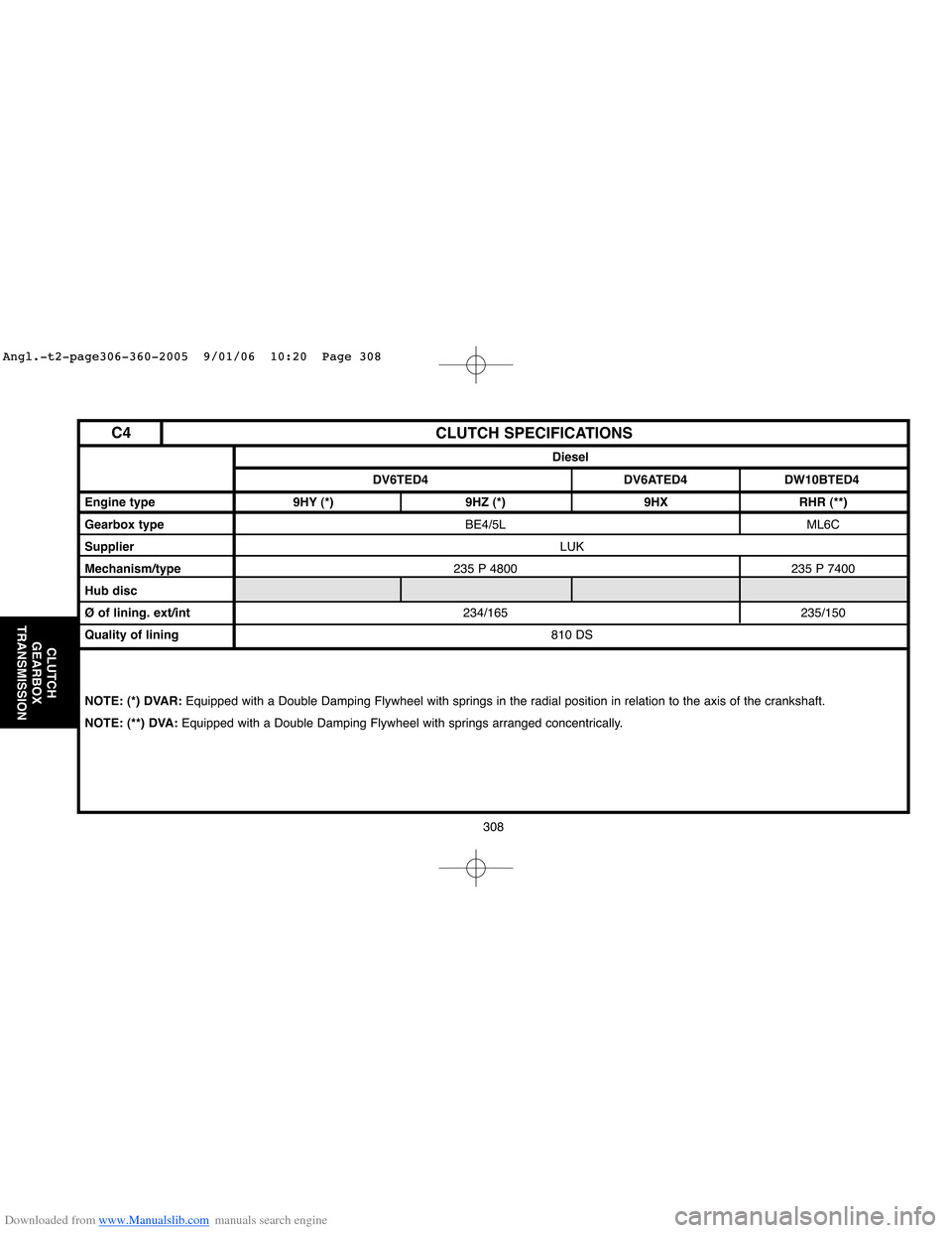
CLUTCH SPECIFICATIONS
Engine type 9HY (*) 9HZ (*) 9HX RHR (**)
Gearbox type BE4/5L ML6C
SupplierLUK
Mechanism/type235 P 4800 235 P 7400
Hub disc
Ø of lining. ext/int234/165 235/150
Quality of lining810 DS
NOTE: (*) DVAR: Equipped with a Double Damping Flywheel with springs in the radial position in relation to the axis of the crankshaft.
NOTE: (**) DVA: Equipped with a Double Damping Flywheel with springs arranged concentrically.
DV6TED4 DV6ATED4 DW10BTED4
Diesel
C4
Angl.-t2-page306-360-2005 9/01/06 10:20 Page 308
Page 315 of 462
Downloaded from www.Manualslib.com manuals search engine CLUTCH
GEARBOX
TRANSMISSION
309
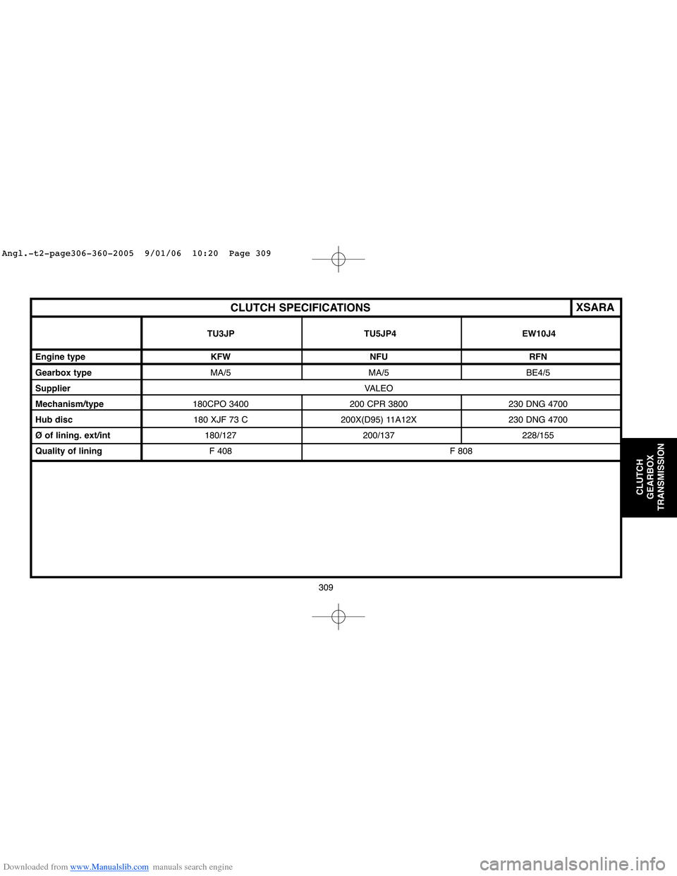
CLUTCH SPECIFICATIONS
Engine type KFW NFU RFN
Gearbox type MA/5 MA/5 BE4/5
SupplierVALEO
Mechanism/type180CPO 3400 200 CPR 3800 230 DNG 4700
Hub disc180 XJF 73 C 200X(D95) 11A12X 230 DNG 4700
Ø of lining. ext/int180/127 200/137 228/155
Quality of liningF 408 F 808
TU3JP TU5JP4 EW10J4
XSARA
Angl.-t2-page306-360-2005 9/01/06 10:20 Page 309
Page 316 of 462
Downloaded from www.Manualslib.com manuals search engine 310
CLUTCH
GEARBOX
TRANSMISSION
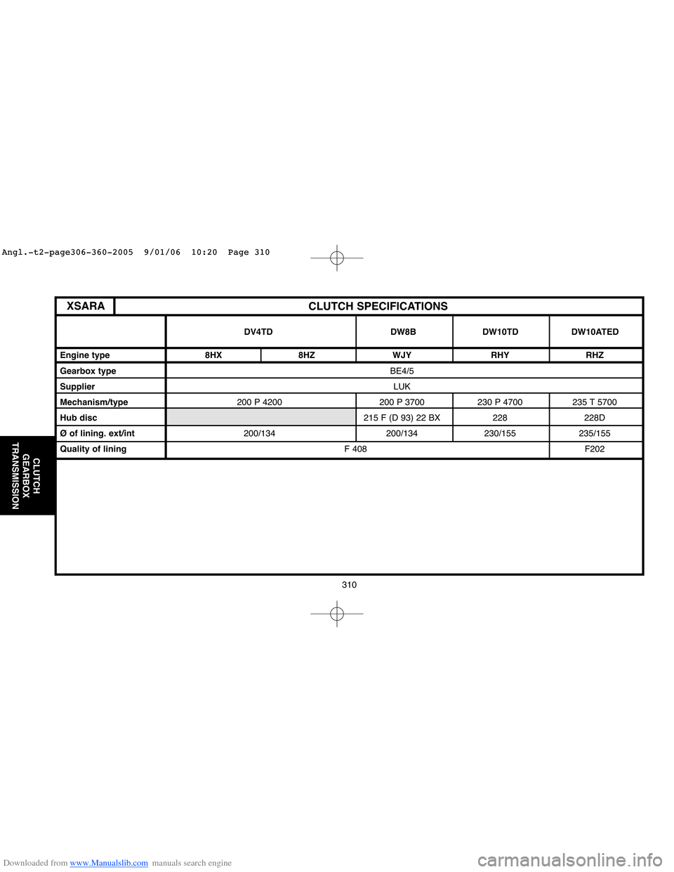
CLUTCH SPECIFICATIONS
Engine type 8HX 8HZ WJY RHY RHZ
Gearbox type BE4/5
SupplierLUK
Mechanism/type200 P 4200 200 P 3700 230 P 4700 235 T 5700
Hub disc215 F (D 93) 22 BX 228 228D
Ø of lining. ext/int200/134 200/134 230/155 235/155
Quality of liningF 408 F202
DV4TD DW8B DW10TD DW10ATED
XSARA
Angl.-t2-page306-360-2005 9/01/06 10:20 Page 310
Page 317 of 462
Downloaded from www.Manualslib.com manuals search engine 311
CLUTCH
GEARBOX
TRANSMISSION
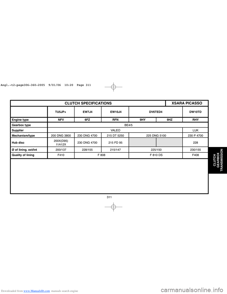
CLUTCH SPECIFICATIONS
Engine type NFV 6FZ RFN 9HY 9HZ RHY
Gearbox type BE4/5
SupplierVALEO LUK
Mechanism/type200 DNG 3800 230 DNG 4700 215 DT 5250 225 DNG 5100 230 P 4700
Hub disc200X(D95)
230 DNG 4700 215 FD 95 228
11A12X
Ø of lining. ext/int200/137 228/155 215/147 225/150 230/155
Quality of liningF410 F 808 F 810 DS F408
TU5JP+ EW7J4 EW10J4 DV6TED4 DW10TD
XSARA PICASSO
Angl.-t2-page306-360-2005 9/01/06 10:20 Page 311
Page 371 of 462
Downloaded from www.Manualslib.com manuals search engine 365
AXLES
SUSPENSION
STEERING
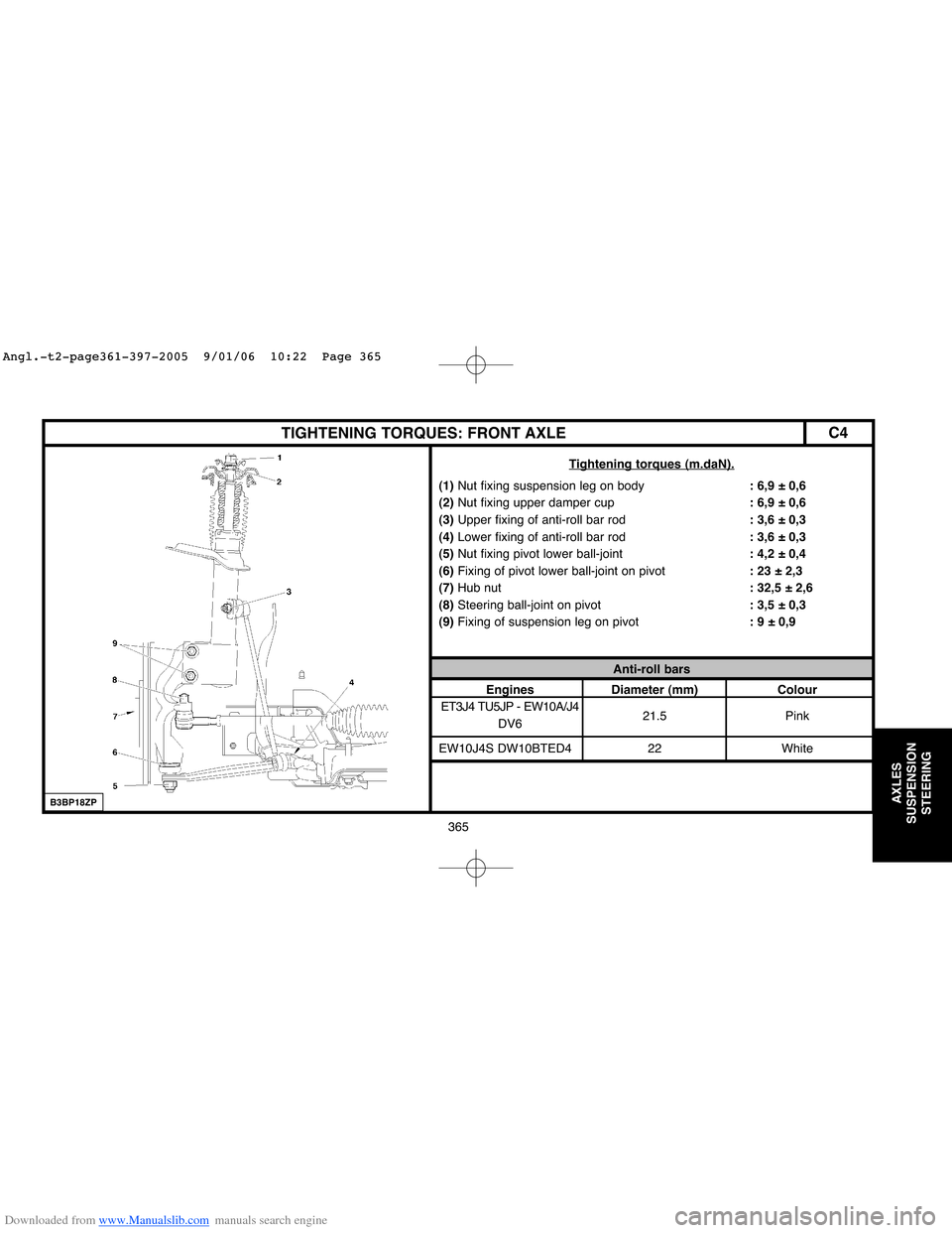
C4TIGHTENING TORQUES: FRONT AXLE
Tightening torques (m.daN).
(1)Nut fixing suspension leg on body: 6,9 ± 0,6
(2) Nut fixing upper damper cup: 6,9 ± 0,6
(3)Upper fixing of anti-roll bar rod: 3,6 ± 0,3
(4)Lower fixing of anti-roll bar rod: 3,6 ± 0,3
(5)Nut fixing pivot lower ball-joint: 4,2 ± 0,4
(6)Fixing of pivot lower ball-joint on pivot: 23 ± 2,3
(7)Hub nut: 32,5 ± 2,6
(8)Steering ball-joint on pivot: 3,5 ± 0,3
(9)Fixing of suspension leg on pivot: 9 ± 0,9
Anti-roll bars
Engines Diameter (mm) Colour
ET3J4 TU5JP - EW10A/J4
DV621.5 Pink
EW10J4S DW10BTED4 22 White
B3BP18ZP
Angl.-t2-page361-397-2005 9/01/06 10:22 Page 365