start Citroen C4 2005 2.G User Guide
[x] Cancel search | Manufacturer: CITROEN, Model Year: 2005, Model line: C4, Model: Citroen C4 2005 2.GPages: 462, PDF Size: 10.48 MB
Page 204 of 462
Downloaded from www.Manualslib.com manuals search engine ENGINE
198
CHECKING THE VALVE TIMING
Engine: NFU
Remove the sparking plugs, to facilitate rotation of the crankshaft.
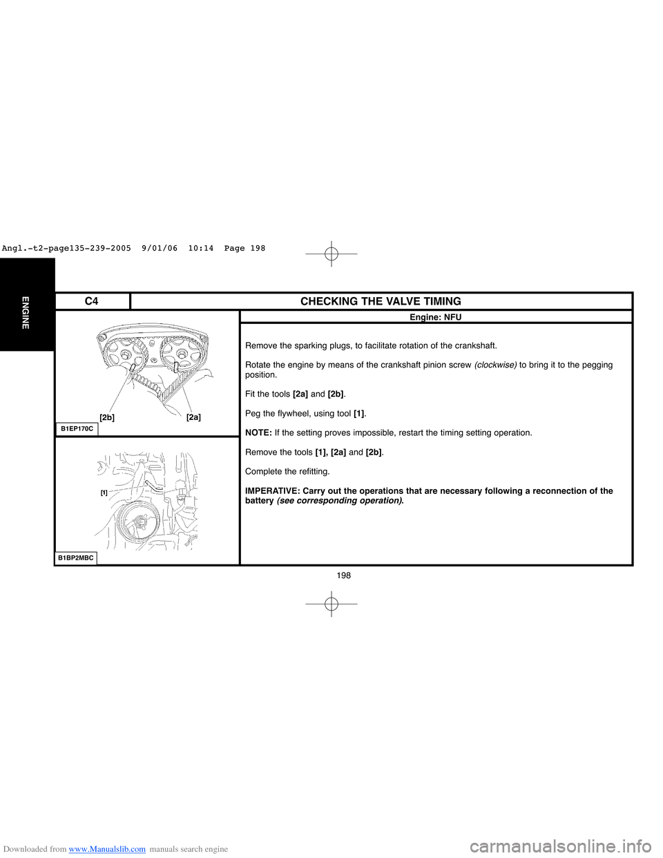
Rotate the engine by means of the crankshaft pinion screw
(clockwise)to bring it to the pegging
position.
Fit the tools [2a]and [2b].
Peg the flywheel, using tool [1].
NOTE:If the setting proves impossible, restart the timing setting operation.
Remove the tools [1], [2a]and [2b].
Complete the refitting.
IMPERATIVE: Carry out the operations that are necessary following a reconnection of the
battery
(see corresponding operation).
B1EP170C
B1BP2MBC
C4
Angl.-t2-page135-239-2005 9/01/06 10:14 Page 198
Page 208 of 462
Downloaded from www.Manualslib.com manuals search engine 202
ENGINECHECKING AND SETTING THE VALVE TIMING
Engine: NFU
Adjusting the fitting tension of the timing belt.
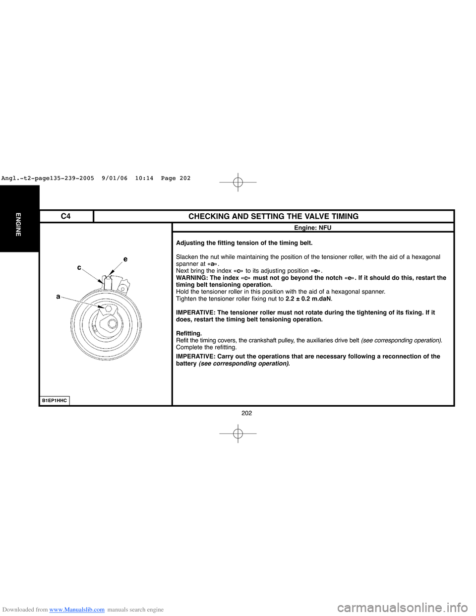
Slacken the nut while maintaining the position of the tensioner roller, with the aid of a hexagonal
spanner at «a».
Next bring the index «c»to its adjusting position «e».
WARNING: The index «c» must not go beyond the notch «e». If it should do this, restart the
timing belt tensioning operation.
Hold the tensioner roller in this position with the aid of a hexagonal spanner.
Tighten the tensioner roller fixing nut to 2.2 ± 0.2 m.daN.
IMPERATIVE: The tensioner roller must not rotate during the tightening of its fixing. If it
does, restart the timing belt tensioning operation.
Refitting.
Refit the timing covers, the crankshaft pulley, the auxiliaries drive belt
(see corresponding operation).
Complete the refitting.
IMPERATIVE: Carry out the operations that are necessary following a reconnection of the
battery
(see corresponding operation).
B1EP1HHC
C4
Angl.-t2-page135-239-2005 9/01/06 10:14 Page 202
Page 214 of 462
Downloaded from www.Manualslib.com manuals search engine 208
ENGINECHECKING AND SETTING THE VALVE TIMING
Engine: RFJ
Tensioning the timing belt.
Refitting (continued).
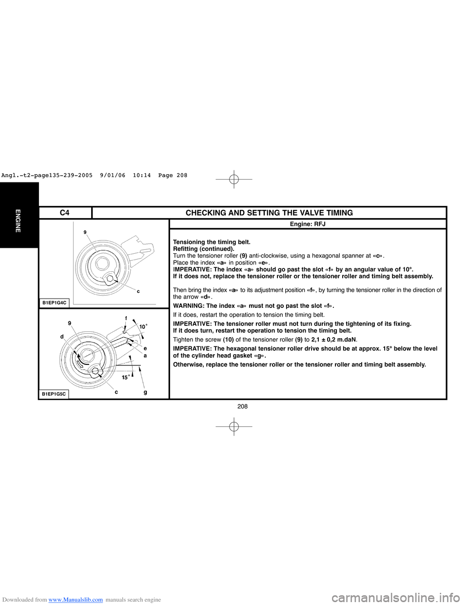
Turn the tensioner roller (9)anti-clockwise, using a hexagonal spanner at «c».
Place the index «a»in position «e».
IMPERATIVE: The index «a» should go past the slot «f» by an angular value of 10°.
If it does not, replace the tensioner roller or the tensioner roller and timing belt assembly.
Then bring the index «a»to its adjustment position «f», by turning the tensioner roller in the direction of
the arrow «d».
WARNING: The index «a» must not go past the slot «f».
If it does, restart the operation to tension the timing belt.
IMPERATIVE: The tensioner roller must not turn during the tightening of its fixing.
If it does turn, restart the operation to tension the timing belt.
Tighten the screw (10)of the tensioner roller (9)to 2,1 ± 0,2 m.daN.
IMPERATIVE: The hexagonal tensioner roller drive should be at approx. 15° below the level
of the cylinder head gasket «g».
Otherwise, replace the tensioner roller or the tensioner roller and timing belt assembly.
B1EP1G4C
B1EP1G5C
C4
Angl.-t2-page135-239-2005 9/01/06 10:14 Page 208
Page 221 of 462
Downloaded from www.Manualslib.com manuals search engine 215
ENGINE
CHECKING AND SETTING THE VALVE TIMING
Engine: RFN
Tensioning the timing belt.
Refitting (continued).
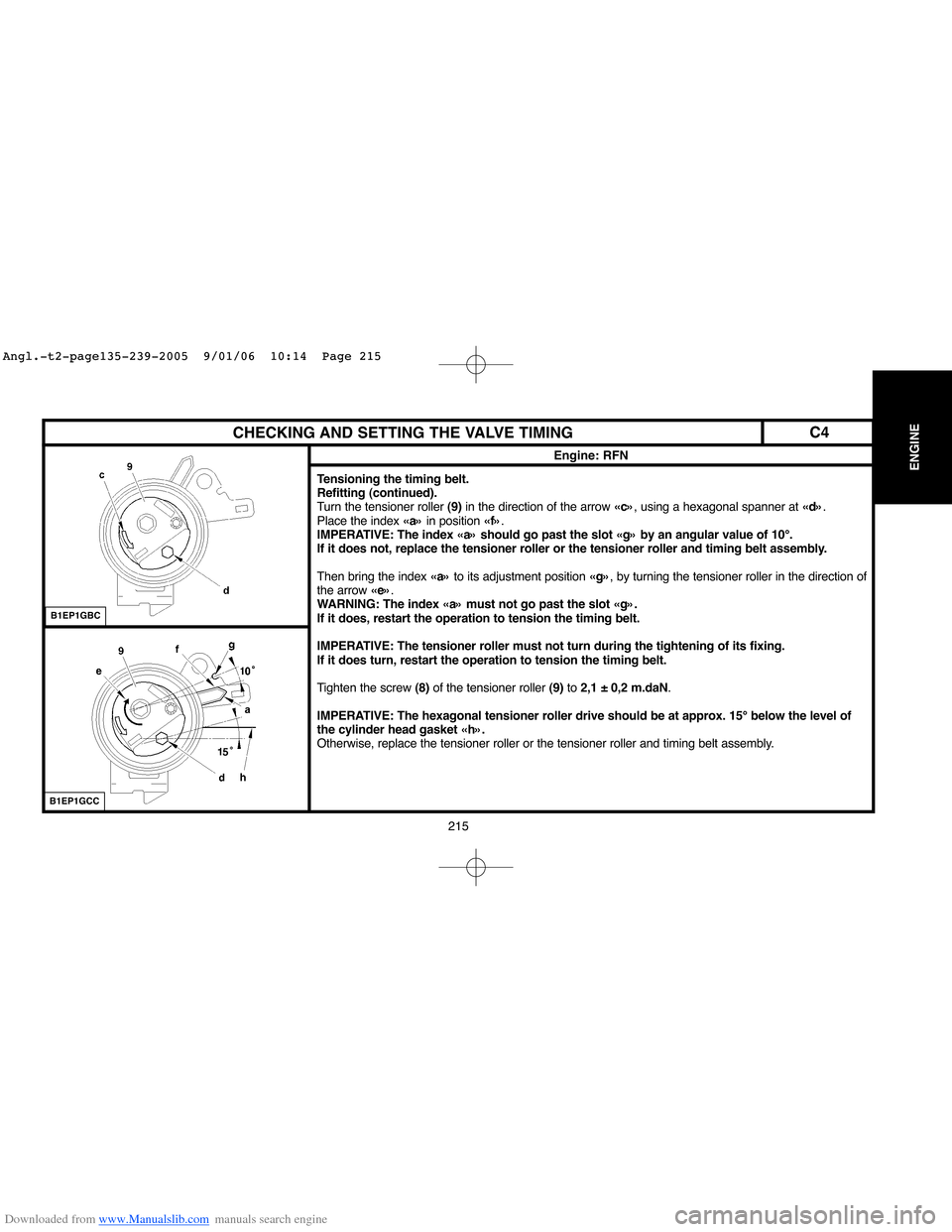
Turn the tensioner roller (9)in the direction of the arrow «c», using a hexagonal spanner at «d».
Place the index «a»in position «f».
IMPERATIVE: The index «a» should go past the slot «g» by an angular value of 10°.
If it does not, replace the tensioner roller or the tensioner roller and timing belt assembly.
Then bring the index «a»to its adjustment position «g», by turning the tensioner roller in the direction of
the arrow «e».
WARNING: The index «a» must not go past the slot «g».
If it does, restart the operation to tension the timing belt.
IMPERATIVE: The tensioner roller must not turn during the tightening of its fixing.
If it does turn, restart the operation to tension the timing belt.
Tighten the screw (8)of the tensioner roller (9)to 2,1 ± 0,2 m.daN.
IMPERATIVE: The hexagonal tensioner roller drive should be at approx. 15° below the level of
the cylinder head gasket «h».
Otherwise, replace the tensioner roller or the tensioner roller and timing belt assembly.
B1EP1GBC
B1EP1GCC
C4
Angl.-t2-page135-239-2005 9/01/06 10:14 Page 215
Page 236 of 462
Downloaded from www.Manualslib.com manuals search engine 230
ENGINECHECKING AND SETTING THE VALVE TIMING
Engine: RFK
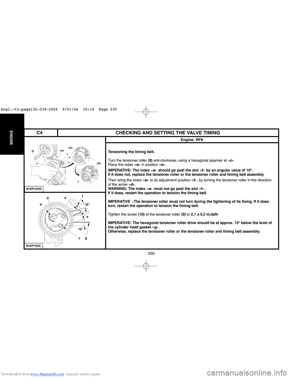
Tensioning the timing belt.
Turn the tensioner roller (9)anti-clockwise, using a hexagonal spanner at «c».
Place the index «a»in position «e».
IMPERATIVE: The index «a» should go past the slot «f» by an angular value of 10°.
If it does not, replace the tensioner roller or the tensioner roller and timing belt assembly.
Then bring the index «a»to its adjustment position «f», by turning the tensioner roller in the direction
of the arrow «d».
WARNING: The index «a» must not go past the slot «f».
If it does, restart the operation to tension the timing belt.
IMPERATIVE : The tensioner roller must not turn during the tightening of its fixing. If it does
turn, restart the operation to tension the timing belt.
Tighten the screw (10)of the tensioner roller (9)to 2,1 ± 0,2 m.daN.
IMPERATIVE: The hexagonal tensioner roller drive should be at approx. 15° below the level of
the cylinder head gasket «g».
Otherwise, replace the tensioner roller or the tensioner roller and timing belt assembly.
B1EP1GXD
B1EP1GZC
C4
Angl.-t2-page135-239-2005 9/01/06 10:14 Page 230
Page 251 of 462
Downloaded from www.Manualslib.com manuals search engine 245
ENGINE
CHECKING AND SETTING THE VALVE TIMING
Engines: 9HX - 9HY - 9HZ
Checking and setting the timing (continued).
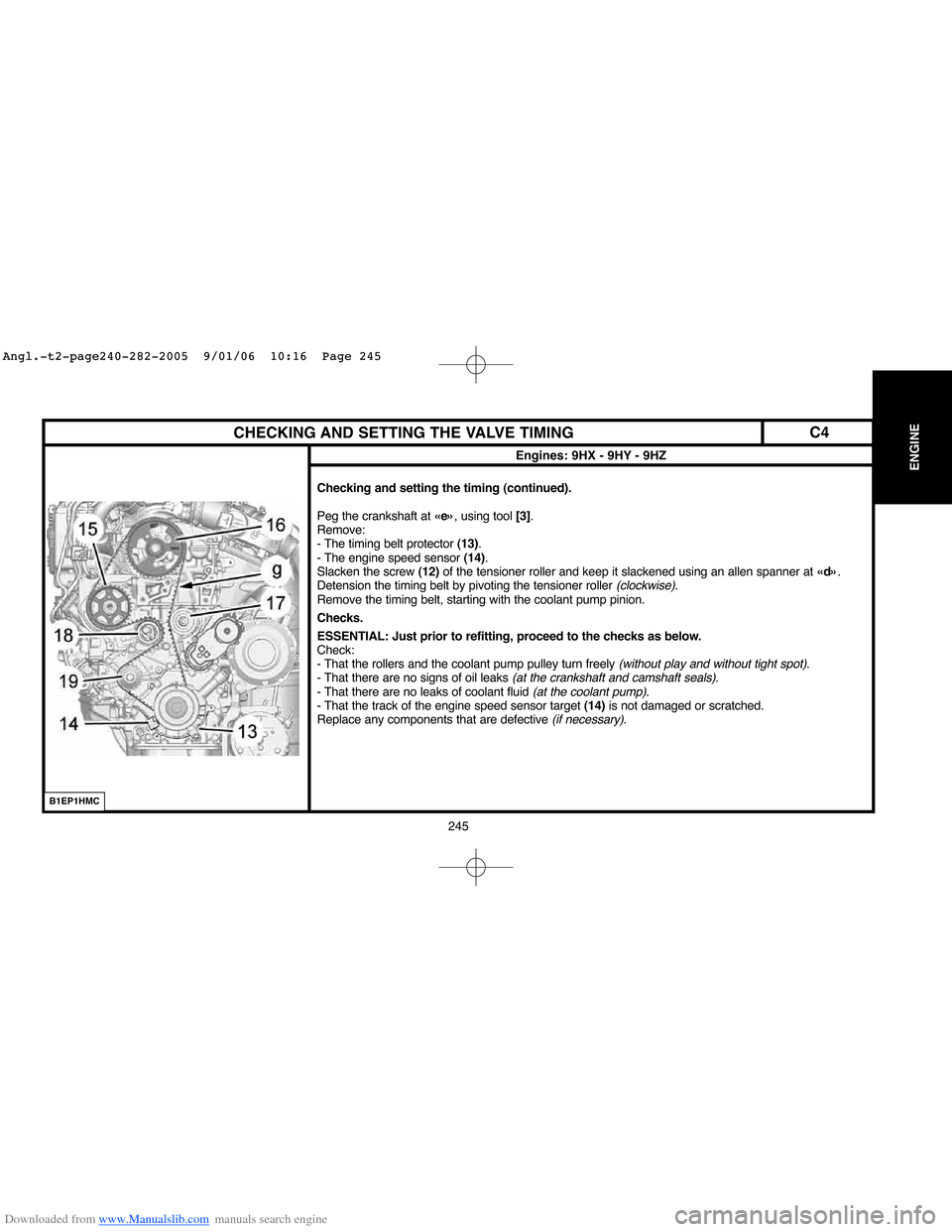
Peg the crankshaft at «e», using tool [3].
Remove:
- The timing belt protector (13).
- The engine speed sensor (14).
Slacken the screw (12)of the tensioner roller and keep it slackened using an allen spanner at «d».
Detension the timing belt by pivoting the tensioner roller
(clockwise).
Remove the timing belt, starting with the coolant pump pinion.
Checks.
ESSENTIAL: Just prior to refitting, proceed to the checks as below.
Check:
- That the rollers and the coolant pump pulley turn freely
(without play and without tight spot).
- That there are no signs of oil leaks (at the crankshaft and camshaft seals).
- That there are no leaks of coolant fluid (at the coolant pump).
- That the track of the engine speed sensor target (14)is not damaged or scratched.
Replace any components that are defective
(if necessary).
B1EP1HMC
C4
Angl.-t2-page240-282-2005 9/01/06 10:16 Page 245
Page 261 of 462
Downloaded from www.Manualslib.com manuals search engine 255
ENGINE
CHECKING AND SETTING THE VALVE TIMING
Engines: 9HZ - 9HY
B1EP1E6D
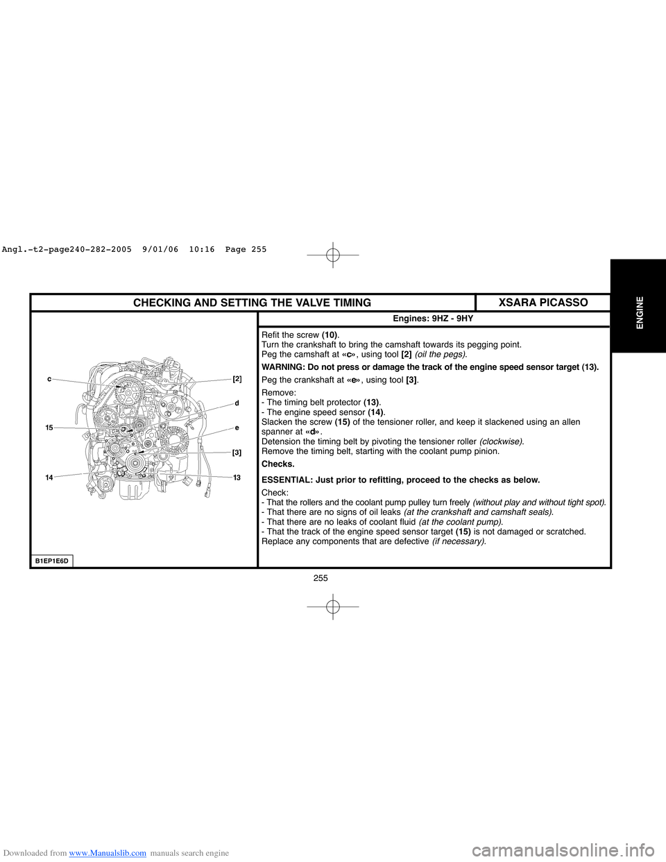
Refit the screw (10).
Turn the crankshaft to bring the camshaft towards its pegging point.
Peg the camshaft at «c», using tool [2]
(oil the pegs).
WARNING: Do not press or damage the track of the engine speed sensor target (13).
Peg the crankshaft at «e», using tool [3].
Remove:
- The timing belt protector (13).
- The engine speed sensor (14).
Slacken the screw (15)of the tensioner roller, and keep it slackened using an allen
spanner at «d».
Detension the timing belt by pivoting the tensioner roller
(clockwise).
Remove the timing belt, starting with the coolant pump pinion.
Checks.
ESSENTIAL: Just prior to refitting, proceed to the checks as below.
Check:
- That the rollers and the coolant pump pulley turn freely
(without play and without tight spot).
- That there are no signs of oil leaks (at the crankshaft and camshaft seals).
- That there are no leaks of coolant fluid (at the coolant pump).
- That the track of the engine speed sensor target (15)is not damaged or scratched.
Replace any components that are defective
(if necessary).
XSARA PICASSO
Angl.-t2-page240-282-2005 9/01/06 10:16 Page 255
Page 284 of 462
Downloaded from www.Manualslib.com manuals search engine 278 278
ENGINECHECKING AND SETTING THE VALVE TIMING
Engine: RHR
Refitting.
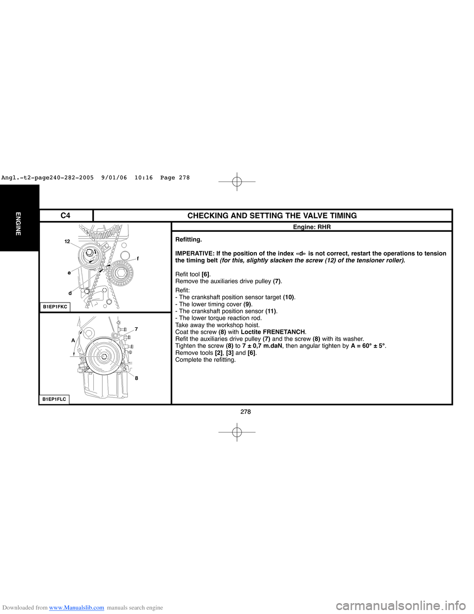
IMPERATIVE: If the position of the index «d» is not correct, restart the operations to tension
the timing belt
(for this, slightly slacken the screw (12) of the tensioner roller).
Refit tool [6].
Remove the auxiliaries drive pulley (7).
Refit:
- The crankshaft position sensor target (10).
- The lower timing cover (9).
- The crankshaft position sensor (11).
- The lower torque reaction rod.
Take away the workshop hoist.
Coat the screw (8)with Loctite FRENETANCH.
Refit the auxiliaries drive pulley (7) and the screw (8)with its washer.
Tighten the screw (8)to 7 ± 0,7 m.daN, then angular tighten by A= 60°±5°.
Remove tools [2], [3] and [6].
Complete the refitting.
B1EP1FKC
B1EP1FLC
C4
Angl.-t2-page240-282-2005 9/01/06 10:16 Page 278
Page 289 of 462
![Citroen C4 2005 2.G User Guide Downloaded from www.Manualslib.com manuals search engine 283
INJECTION
CHECKS: LOW PRESSURE FUEL SUPPLY CIRCUIT
Tools.
[1] Ø 10 mmlow pressure connector: 4215-T
[2]Pressure gauge for testing boost pr Citroen C4 2005 2.G User Guide Downloaded from www.Manualslib.com manuals search engine 283
INJECTION
CHECKS: LOW PRESSURE FUEL SUPPLY CIRCUIT
Tools.
[1] Ø 10 mmlow pressure connector: 4215-T
[2]Pressure gauge for testing boost pr](/img/9/4138/w960_4138-288.png)
Downloaded from www.Manualslib.com manuals search engine 283
INJECTION
CHECKS: LOW PRESSURE FUEL SUPPLY CIRCUIT
Tools.
[1] Ø 10 mmlow pressure connector: 4215-T
[2]Pressure gauge for testing boost pressure: 4073-T.A Toolkit 4073-T
IMPERATIVE: Respect the safety and cleanliness specific to high pressure diesel injection
engines.
Link tools [1]and [2] in series between the fuel high pressure pump and the fuel filter.
ESSENTIAL: Check that the tool [2] is clean.
Check the negative pressure according to the table below:
Vacuum Observations
10 ± 5 cmHgEngine driven by the starter motor
20 ± 5 cmHgEngine running under full load
60 ± 5 cmHgSupply circuit obstructed
(full tank strainer, piping, fuel filter)
B1BP2WHC
Engines: 8HX - 8HZ
XSARA
Angl.-t2-page283-305-2005 9/01/06 10:18 Page 283
Page 290 of 462
![Citroen C4 2005 2.G User Guide Downloaded from www.Manualslib.com manuals search engine 284
INJECTION
CHECKS: LOW PRESSURE FUEL SUPPLY CIRCUIT
Tools.
[1] Ø 10 mmlow pressure connector: 4215-T
[2]Pressure gauge for testing boost pr Citroen C4 2005 2.G User Guide Downloaded from www.Manualslib.com manuals search engine 284
INJECTION
CHECKS: LOW PRESSURE FUEL SUPPLY CIRCUIT
Tools.
[1] Ø 10 mmlow pressure connector: 4215-T
[2]Pressure gauge for testing boost pr](/img/9/4138/w960_4138-289.png)
Downloaded from www.Manualslib.com manuals search engine 284
INJECTION
CHECKS: LOW PRESSURE FUEL SUPPLY CIRCUIT
Tools.
[1] Ø 10 mmlow pressure connector: 4215-T
[2]Pressure gauge for testing boost pressure: 4073-T.A Toolkit 4073-T
IMPERATIV: Respect the safety and cleanliness specific to high pressure diesel injection
engines.
Remove the air filter duct.
Link tool [1]in series, downstream of the injectors, between the fuel high pressure pump and the
fuel filter at «a»and «b».
WARNING: Any checking of pressure downstream of the fuel filter is prohibited.
Switch on the ignition.
Check the pressure :
Vacuum measured by the pressure gauge [2]:
Vacuum Observations
10 ± 0,5 cmHgEngine driven by the starter motor.
20 ± 0,5 cmHgEngine running under full load
60 ± 0,5 cmHgSupply circuit obstructed
(full tank strainer, piping, fuel filter)
B1CP0GFD
Engines: 9HX - 9HY - 9HZ
C4
Angl.-t2-page283-305-2005 9/01/06 10:18 Page 284