drain Citroen C4 2005 2.G Owner's Manual
[x] Cancel search | Manufacturer: CITROEN, Model Year: 2005, Model line: C4, Model: Citroen C4 2005 2.GPages: 462, PDF Size: 10.48 MB
Page 353 of 462
Downloaded from www.Manualslib.com manuals search engine 347
CLUTCH
GEARBOX
TRANSMISSION
TIGHTENING TORQUES: AL4 AUTOMATIC GEARBOX
Engines: NFU - RFJ
B2CP3EDD
B2CP3X7D
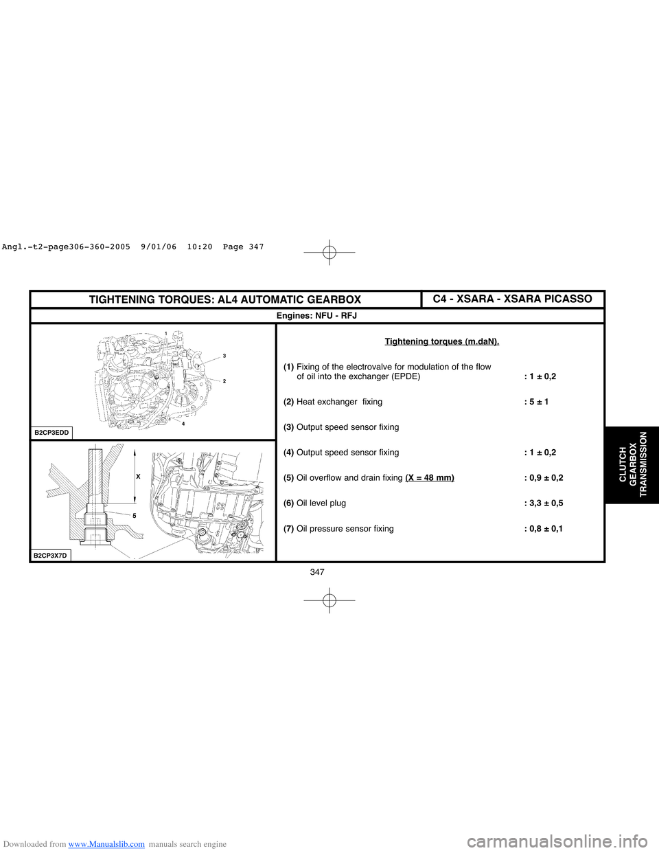
Tightening torques (m.daN).
(1) Fixing of the electrovalve for modulation of the flow
of oil into the exchanger (EPDE): 1 ± 0,2
(2)Heat exchanger fixing: 5 ± 1
(3) Output speed sensor fixing
(4)Output speed sensor fixing: 1 ± 0,2
(5)Oil overflow and drain fixing(X = 48 mm)
: 0,9 ± 0,2
(6)Oil level plug: 3,3 ± 0,5
(7)Oil pressure sensor fixing: 0,8 ± 0,1
C4 - XSARA - XSARA PICASSO
Angl.-t2-page306-360-2005 9/01/06 10:20 Page 347
Page 379 of 462
Downloaded from www.Manualslib.com manuals search engine 373
AXLES
SUSPENSION
STEERING
CHECKING THE POWER STEERING ASSISTANCE PRESSURE
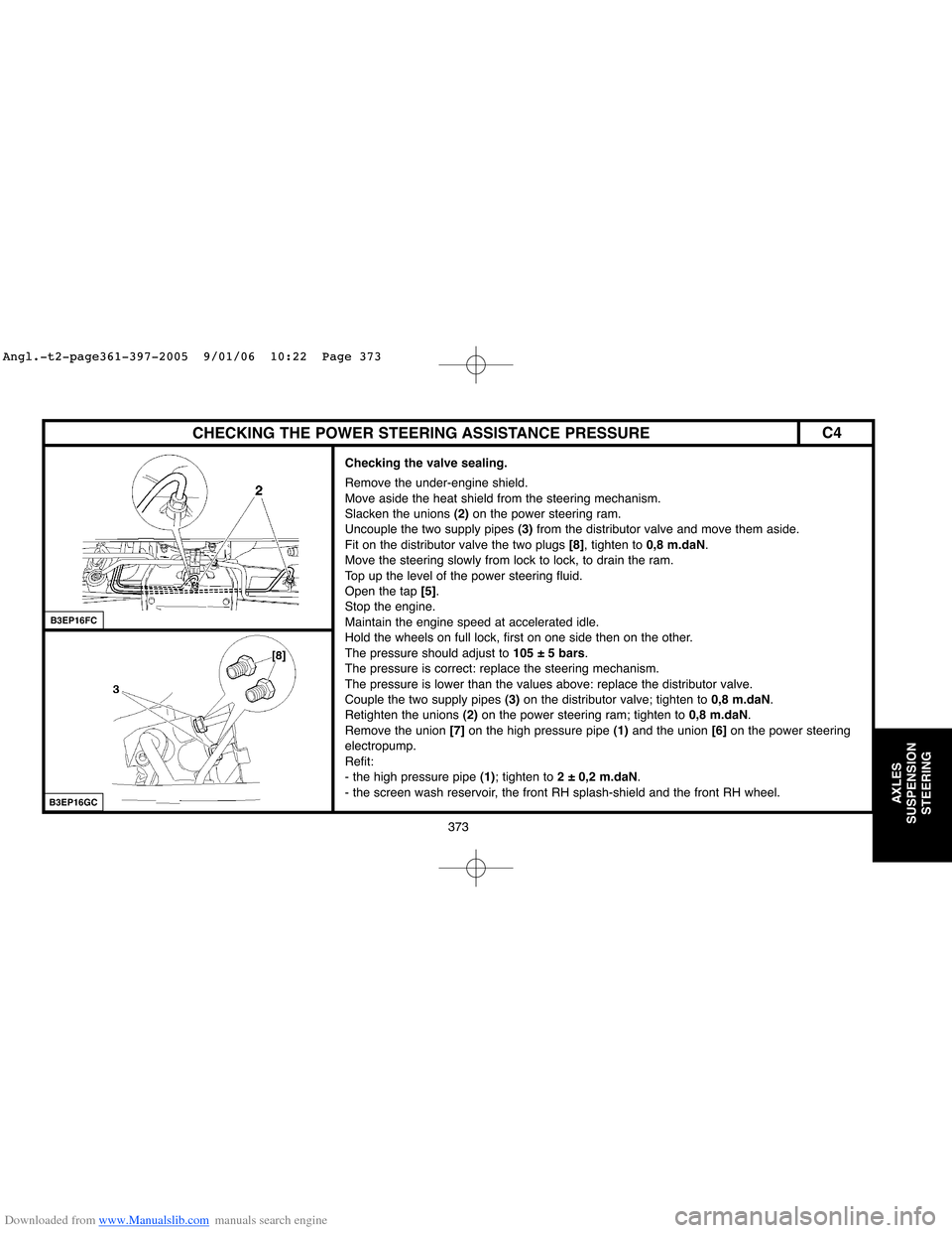
Checking the valve sealing.
Remove the under-engine shield.
Move aside the heat shield from the steering mechanism.
Slacken the unions (2)on the power steering ram.
Uncouple the two supply pipes (3)from the distributor valve and move them aside.
Fit on the distributor valve the two plugs [8], tighten to 0,8 m.daN.
Move the steering slowly from lock to lock, to drain the ram.
Top up the level of the power steering fluid.
Open the tap [5].
Stop the engine.
Maintain the engine speed at accelerated idle.
Hold the wheels on full lock, first on one side then on the other.
The pressure should adjust to 105 ± 5 bars.
The pressure is correct: replace the steering mechanism.
The pressure is lower than the values above: replace the distributor valve.
Couple the two supply pipes (3)on the distributor valve; tighten to 0,8 m.daN.
Retighten the unions (2)on the power steering ram; tighten to 0,8 m.daN.
Remove the union [7]on the high pressure pipe (1)and the union [6]on the power steering
electropump.
Refit:
- the high pressure pipe (1); tighten to 2 ± 0,2 m.daN.
- the screen wash reservoir, the front RH splash-shield and the front RH wheel.
B3EP16FC
B3EP16GC
C4
Angl.-t2-page361-397-2005 9/01/06 10:22 Page 373
Page 412 of 462
![Citroen C4 2005 2.G Owners Manual Downloaded from www.Manualslib.com manuals search engine 406
BRAKES
B3FP7EQC
BLEEDING AND FILLING THE BRAKING SYSTEM
Tools.
[1]Bleeding apparatus: «LURO» or similar
[2]LEXIA diagnostic tool: 4171-T
Citroen C4 2005 2.G Owners Manual Downloaded from www.Manualslib.com manuals search engine 406
BRAKES
B3FP7EQC
BLEEDING AND FILLING THE BRAKING SYSTEM
Tools.
[1]Bleeding apparatus: «LURO» or similar
[2]LEXIA diagnostic tool: 4171-T](/img/9/4138/w960_4138-411.png)
Downloaded from www.Manualslib.com manuals search engine 406
BRAKES
B3FP7EQC
BLEEDING AND FILLING THE BRAKING SYSTEM
Tools.
[1]Bleeding apparatus: «LURO» or similar
[2]LEXIA diagnostic tool: 4171-T
[3]PROXIA diagnostic tool: 4165-T
NOTE:Bleeding of the secondary braking circuit is done with the aid of diagnostic tools [2]and [3].
Draining of the brake fluid reservoir.
Remove the screws (3)and the battery tray (2).
Remove the filter of the brake fluid reservoir (4).
Drain the brake fluid reservoir (4)to the maximum extent
(if necessary, use a clean syringe).
Remove the screws (1).
Uncouple the clickfit union at «a».
Remove the brake fluid reservoir (4).
C4
Angl.-t2-PAGE398-427-2005 9/01/06 10:24 Page 406
Page 433 of 462
Downloaded from www.Manualslib.com manuals search engine 427
BRAKES
BLEEDING THE BRAKING SYSTEMXSARA PICASSO
Tools Bleeding equipment of type «LURO» or similar.
IMPERATIVE: For bleeding the secondary circuit, use ELIT, LEXIA or PROXIA diagnostic tools.
Draining.
Drain the brake fluid reservoir as empty as possible using a syringe.
Disconnect the brake fluid warning lamp connector.
Retrieve the brake fluid reservoir from its supply pipes by pulling upwards.
Finish emptying the reservoir of brake fluid.
Clean the brake fluid reservoir.
Refit the brake fluid reservoir.
Reconnect the brake fluid warning lamp connector.
Filling.
Refill the reservoir with brake fluid.
WARNING: Use only the recommended hydraulic fluids.
Bleeding.
NOTE:Two technicians are required.
IMPERATIVE: During bleed operations, ensure that the level of brake fluid is maintained
in the reservoir and top it up, use only new brake fluid.
Bleed each wheel cylinder, proceeding in the following order:
- Rear right hand wheel.
- Front left hand wheel.
- Rear left hand wheel.
- Front right hand wheel.
Angl.-t2-PAGE398-427-2005 9/01/06 10:24 Page 427
Page 435 of 462
Downloaded from www.Manualslib.com manuals search engine 429
AIR
CONDITIONING
ESSENTIAL: The compressor lubricant is extremely hygroscopic; always use FRESH oil.
Checking the compressor oil level
There are three specific cases:
- 1/Repairs to a system without leaks.
- 2/Slow leak.
- 3/Fast leak.
1/ Repairing a system without leaks.
a) - Using draining/recovery equipment not fitted with an oil decanter.
- Drain the system as slowly as possible via the LOW PRESSUREvalve, so as not to lose any oil.
- No more oil should be added when filling the system with R 134.afluid.
b) - Using draining/filling equipment fitted with an oil decanter.
- Drain the R 134.afluid from the system in accordance with the instructions in the equipment handbook.
- Measure the amount of oil recovered.
- Add the same amount of NEWoil when filling the system with R 134.afluid.
c) - Replacing a compressor.
- Remove the old compressor, drain it and measure the oil quantity.
- Drain the new compressor
(supplied full), so that the same amount of NEWoil is left in the compressor as was in the old compressor.
- No more oil should be added when filling the system with R 134.a fluid.
SPECIAL FEATURES: AIR CONDITIONING SYSTEM (R 134.a)
Compressor lubricant
Angl.-t2-page428-456-2005 9/01/06 10:25 Page 429
Page 436 of 462
Downloaded from www.Manualslib.com manuals search engine 430
AIR
CONDITIONING
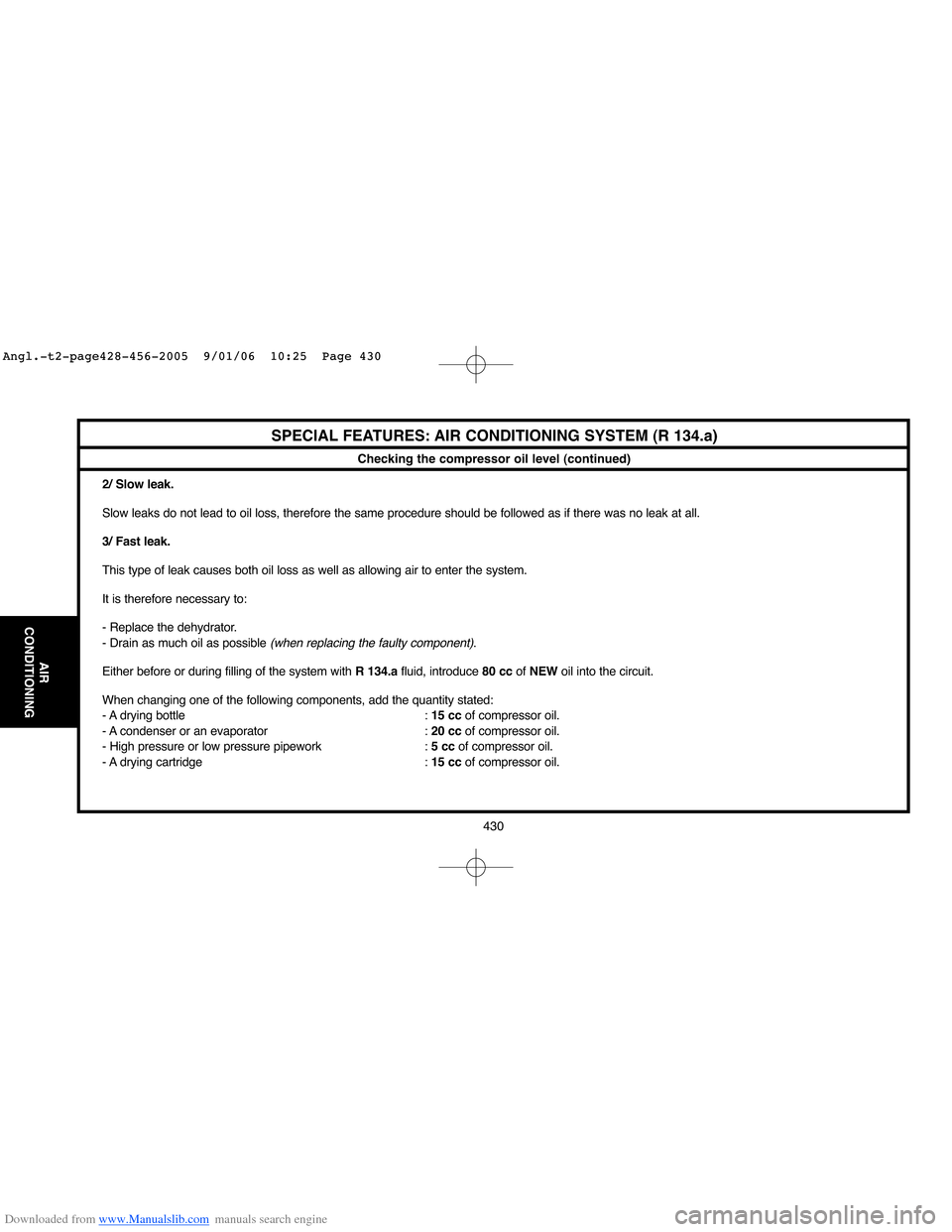
Checking the compressor oil level (continued)
2/ Slow leak.
Slow leaks do not lead to oil loss, therefore the same procedure should be followed as if there was no leak at all.
3/ Fast leak.
This type of leak causes both oil loss as well as allowing air to enter the system.
It is therefore necessary to:
- Replace the dehydrator.
- Drain as much oil as possible
(when replacing the faulty component).
Either before or during filling of the system with R 134.afluid, introduce 80 ccof NEWoil into the circuit.
When changing one of the following components, add the quantity stated:
- A drying bottle : 15 ccof compressor oil.
- A condenser or an evaporator : 20 ccof compressor oil.
- High pressure or low pressure pipework : 5 ccof compressor oil.
- A drying cartridge : 15 ccof compressor oil.
SPECIAL FEATURES: AIR CONDITIONING SYSTEM (R 134.a)
Angl.-t2-page428-456-2005 9/01/06 10:25 Page 430