sensor Citroen C4 2005 2.G Owner's Manual
[x] Cancel search | Manufacturer: CITROEN, Model Year: 2005, Model line: C4, Model: Citroen C4 2005 2.GPages: 462, PDF Size: 10.48 MB
Page 252 of 462
Downloaded from www.Manualslib.com manuals search engine 246
ENGINECHECKING AND SETTING THE VALVE TIMING
Engines: 9HX - 9HY - 9HZ
Checking and setting the timing (continued).
Refitting.
Fit the timing belt on the crankshaft pinion.
Position the belt on the guide roller, belt well tensioned.
Refit:
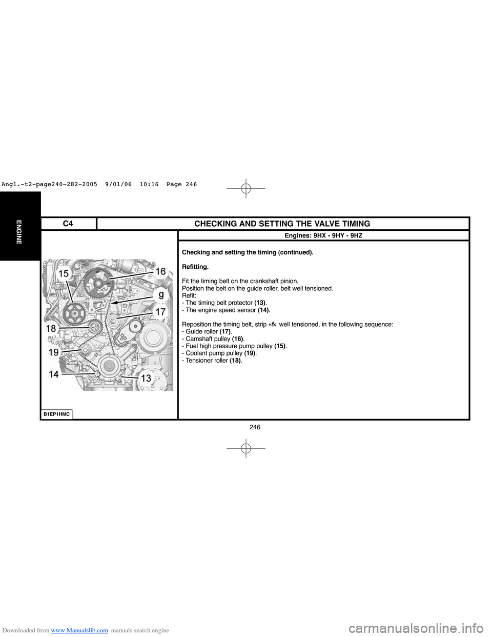
- The timing belt protector (13).
- The engine speed sensor (14).
Reposition the timing belt, strip «f»well tensioned, in the following sequence:
- Guide roller (17).
- Camshaft pulley (16).
- Fuel high pressure pump pulley (15).
- Coolant pump pulley (19).
- Tensioner roller (18).
B1EP1HMC
C4
Angl.-t2-page240-282-2005 9/01/06 10:16 Page 246
Page 253 of 462
Downloaded from www.Manualslib.com manuals search engine 247
ENGINE
CHECKING AND SETTING THE VALVE TIMING
Engines: 9HX - 9HY - 9HZ
Adjusting the timing belt tension.
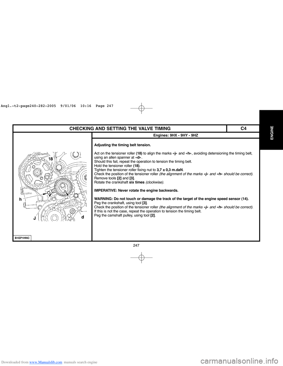
Act on the tensioner roller (18)to align the marks «j»and «h», avoiding detensioning the timing belt,
using an allen spanner at «d».
Should this fail, repeat the operation to tension the timing belt.
Hold the tensioner roller (18).
Tighten the tensioner roller fixing nut to 3,7 ± 0,3 m.daN.
Check the position of the tensioner roller
(the alignment of the marks «j» and «h»should be correct).
Remove tools [2]and [3].
Rotate the crankshaft six times
(clockwise).
IMPERATIVE: Never rotate the engine backwards.
WARNING: Do not touch or damage the track of the target of the engine speed sensor (14).
Peg the crankshaft, using tool [3].
Check the position of the tensioner roller
(the alignment of the marks «j»and «h»should be correct).
If this is not the case, repeat the operation to tension the timing belt.
Peg the camshaft pulley, using tool [2].
B1EP1HNC
C4
Angl.-t2-page240-282-2005 9/01/06 10:16 Page 247
Page 261 of 462
Downloaded from www.Manualslib.com manuals search engine 255
ENGINE
CHECKING AND SETTING THE VALVE TIMING
Engines: 9HZ - 9HY
B1EP1E6D
Refit the screw (10).
Turn the crankshaft to bring the camshaft towards its pegging point.
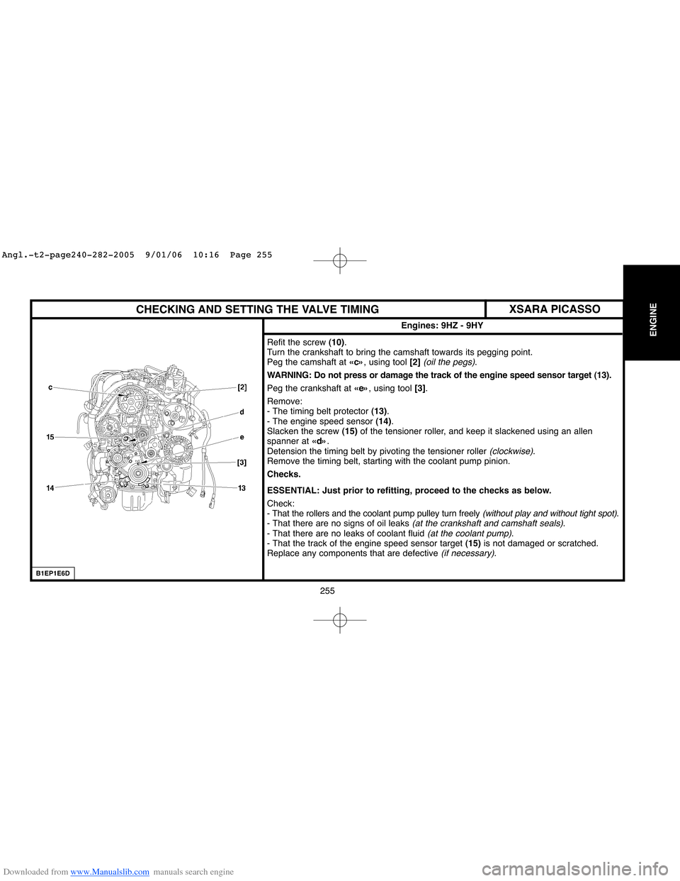
Peg the camshaft at «c», using tool [2]
(oil the pegs).
WARNING: Do not press or damage the track of the engine speed sensor target (13).
Peg the crankshaft at «e», using tool [3].
Remove:
- The timing belt protector (13).
- The engine speed sensor (14).
Slacken the screw (15)of the tensioner roller, and keep it slackened using an allen
spanner at «d».
Detension the timing belt by pivoting the tensioner roller
(clockwise).
Remove the timing belt, starting with the coolant pump pinion.
Checks.
ESSENTIAL: Just prior to refitting, proceed to the checks as below.
Check:
- That the rollers and the coolant pump pulley turn freely
(without play and without tight spot).
- That there are no signs of oil leaks (at the crankshaft and camshaft seals).
- That there are no leaks of coolant fluid (at the coolant pump).
- That the track of the engine speed sensor target (15)is not damaged or scratched.
Replace any components that are defective
(if necessary).
XSARA PICASSO
Angl.-t2-page240-282-2005 9/01/06 10:16 Page 255
Page 262 of 462
Downloaded from www.Manualslib.com manuals search engine 256
ENGINE
CHECKING AND SETTING THE VALVE TIMING
Engines: 9HZ - 9HY
B1EP1E7D
Refitting.
Fit the timing belt on the crankshaft pinion.
Position the belt on the guide roller, belt well tensioned.
Refit:
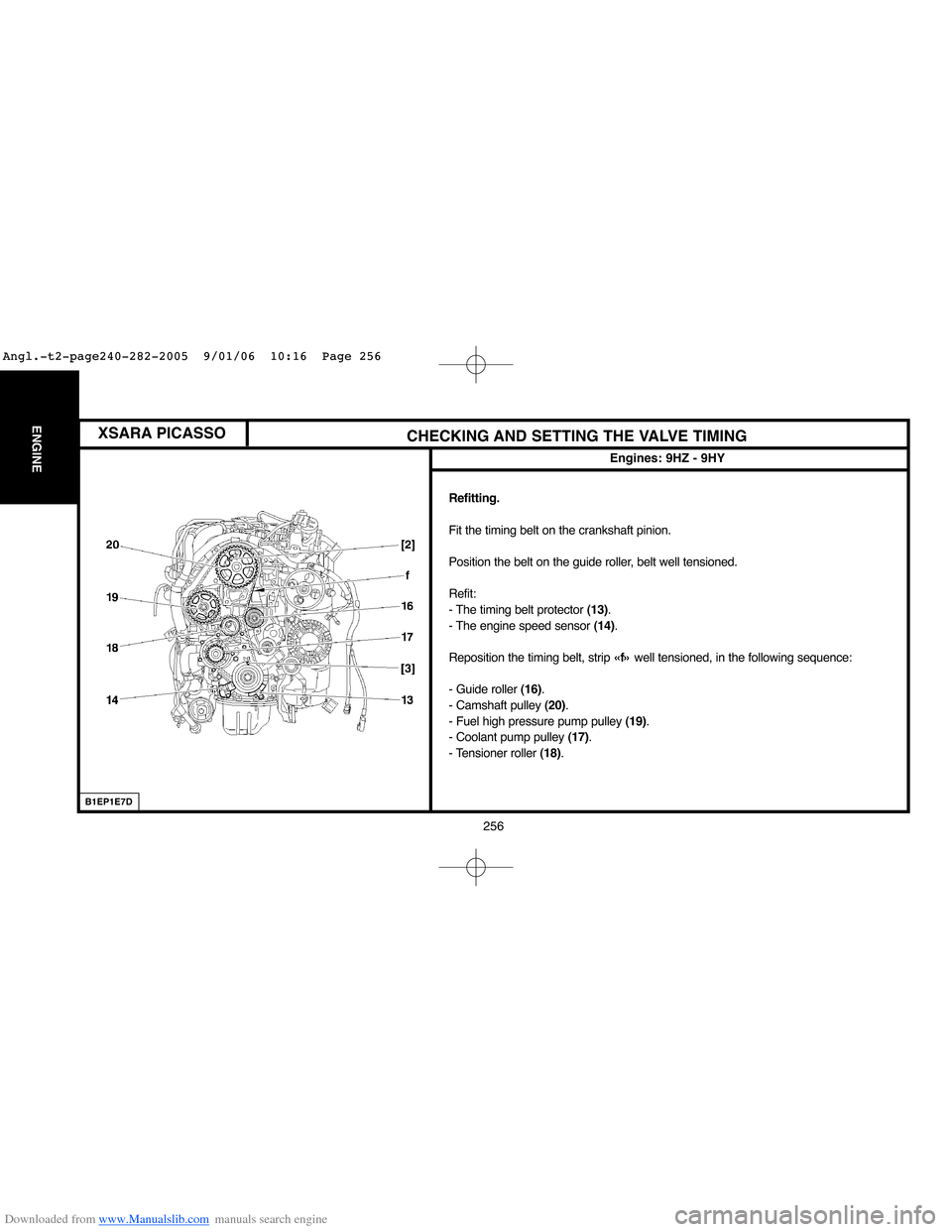
- The timing belt protector (13).
- The engine speed sensor(14).
Reposition the timing belt, strip «f»well tensioned, in the following sequence:
- Guide roller (16).
- Camshaft pulley (20).
- Fuel high pressure pump pulley (19).
- Coolant pump pulley (17).
- Tensioner roller (18).
XSARA PICASSO
Angl.-t2-page240-282-2005 9/01/06 10:16 Page 256
Page 263 of 462
Downloaded from www.Manualslib.com manuals search engine 257
ENGINE
CHECKING AND SETTING THE VALVE TIMING
Engines: 9HZ - 9HY
B1EP1E8C
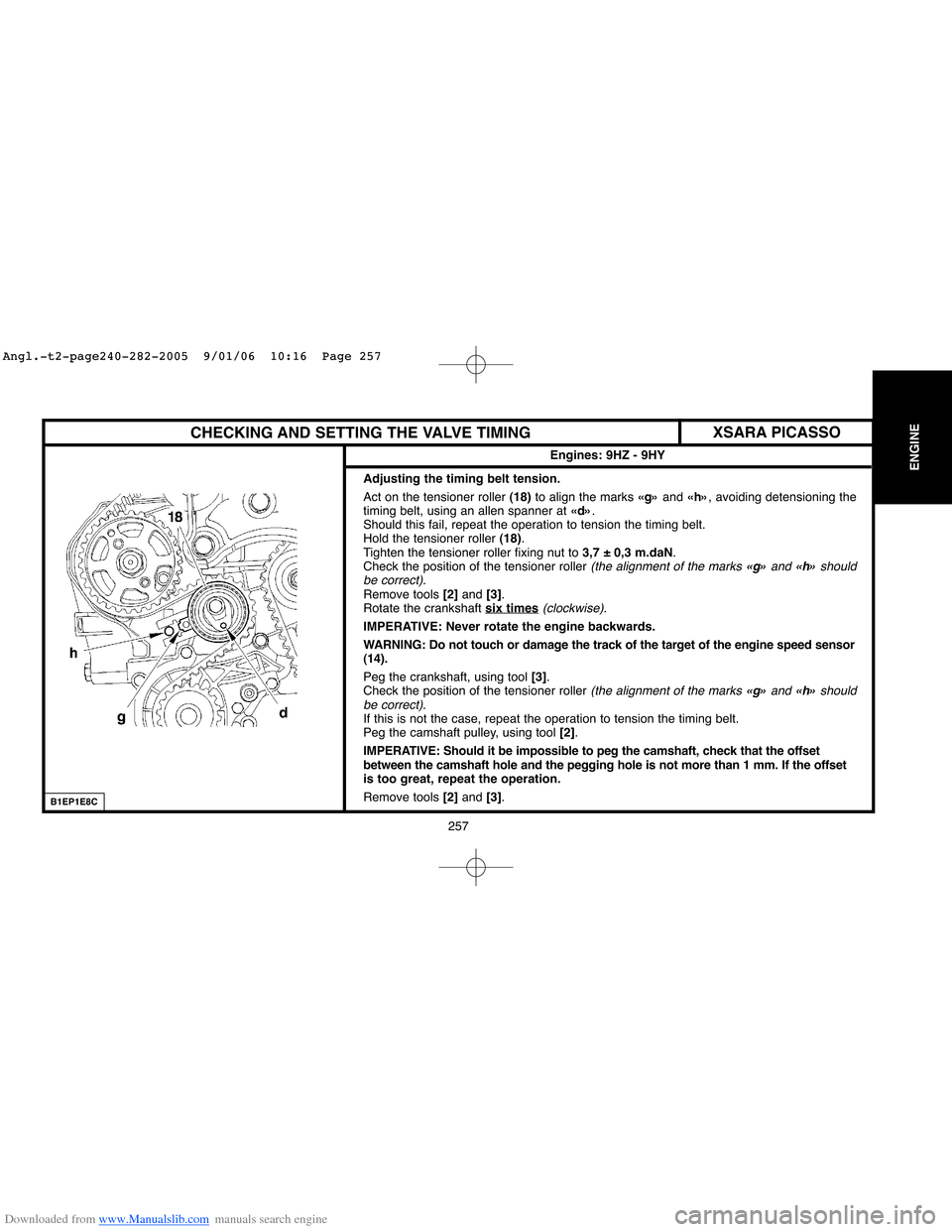
Adjusting the timing belt tension.
Act on the tensioner roller (18)to align the marks «g»and «h», avoiding detensioning the
timing belt, using an allen spanner at «d».
Should this fail, repeat the operation to tension the timing belt.
Hold the tensioner roller (18).
Tighten the tensioner roller fixing nut to 3,7 ± 0,3 m.daN.
Check the position of the tensioner roller
(the alignment of the marks «g»and «h»should
be correct).
Remove tools [2] and [3].
Rotate the crankshaft six times
(clockwise).
IMPERATIVE: Never rotate the engine backwards.
WARNING: Do not touch or damage the track of the target of the engine speed sensor
(14).
Peg the crankshaft, using tool[3].
Check the position of the tensioner roller
(the alignment of the marks «g» and «h»should
be correct).
If this is not the case, repeat the operation to tension the timing belt.
Peg the camshaft pulley, using tool [2].
IMPERATIVE: Should it be impossible to peg the camshaft, check that the offset
between the camshaft hole and the pegging hole is not more than 1 mm. If the offset
is too great, repeat the operation.
Remove tools [2] and [3].
XSARA PICASSO
Angl.-t2-page240-282-2005 9/01/06 10:16 Page 257
Page 277 of 462
![Citroen C4 2005 2.G Owners Manual Downloaded from www.Manualslib.com manuals search engine 271
ENGINE
CHECKING THE VALVE TIMING
Engine: RHR
Tools.
[1] Kit of plugs: (-).0188.T
[2] Double flywheel setting peg: (-).0188.X Toolkit 0188-T Citroen C4 2005 2.G Owners Manual Downloaded from www.Manualslib.com manuals search engine 271
ENGINE
CHECKING THE VALVE TIMING
Engine: RHR
Tools.
[1] Kit of plugs: (-).0188.T
[2] Double flywheel setting peg: (-).0188.X Toolkit 0188-T](/img/9/4138/w960_4138-276.png)
Downloaded from www.Manualslib.com manuals search engine 271
ENGINE
CHECKING THE VALVE TIMING
Engine: RHR
Tools.
[1] Kit of plugs: (-).0188.T
[2] Double flywheel setting peg: (-).0188.X Toolkit 0188-T
[3]Camshaft setting peg: (-).0188.M
IMPERATIVE: Respect the safety and cleanliness requirements specific to High pressure Diesel
injection (HDi) engine versions.
Remove the engine cover and the battery.
Disconnect the negative terminal of the battery.
Raise and support the front of the vehicle.
Remove the under-engine sound-deadening and the front RH splash-shield.
Uncouple, plug and move aside, using tool [1], the fuel supply and fuel return pipes..
Suspend the engine, using a workshop hoist.
Remove the engine support bracket and the engine support.
Move aside the electrical harness (1).
Remove:
- The camshaft position sensor.
- The inlet cylinder head cover (2).
- The upper timing cover screws.
- The upper timing cover (3).
B1EP1GFC
C4
Angl.-t2-page240-282-2005 9/01/06 10:16 Page 271
Page 281 of 462
Downloaded from www.Manualslib.com manuals search engine 275
ENGINE
CHECKING AND SETTING THE VALVE TIMING
Engine: RHR
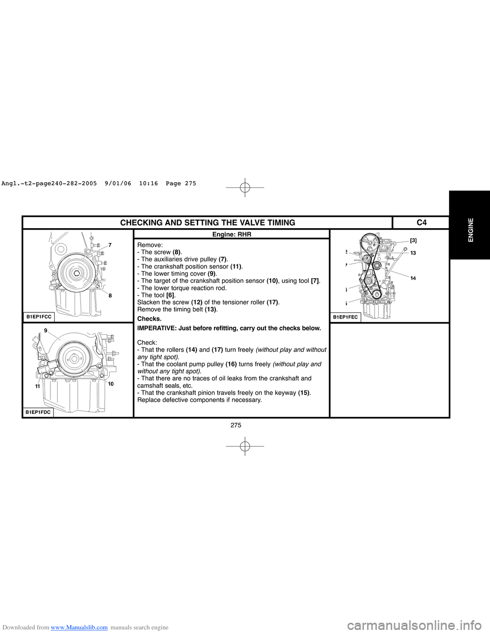
Remove:
- The screw (8).
- The auxiliaries drive pulley (7).
- The crankshaft position sensor (11).
- The lower timing cover (9).
- The target of the crankshaft position sensor (10), using tool [7].
- The lower torque reaction rod.
- The tool [6].
Slacken the screw (12)of the tensioner roller (17).
Remove the timing belt (13).
Checks.
IMPERATIVE: Just before refitting, carry out the checks below.
Check:
- That the rollers (14)and (17)turn freely
(without play and without
any tight spot).
- That the coolant pump pulley (16)turns freely (without play and
without any tight spot).
- That there are no traces of oil leaks from the crankshaft and
camshaftseals, etc.
- That the crankshaft pinion travels freely on the keyway (15).
Replace defective components if necessary.
B1EP1FCC
B1EP1FDC
B1EP1FEC
C4
Angl.-t2-page240-282-2005 9/01/06 10:16 Page 275
Page 284 of 462
Downloaded from www.Manualslib.com manuals search engine 278 278
ENGINECHECKING AND SETTING THE VALVE TIMING
Engine: RHR
Refitting.
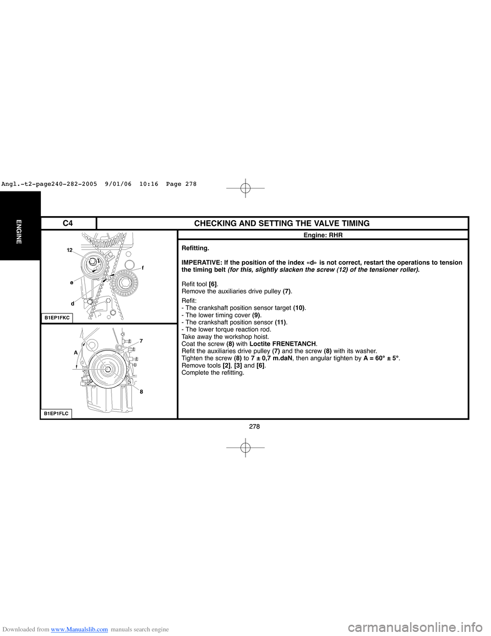
IMPERATIVE: If the position of the index «d» is not correct, restart the operations to tension
the timing belt
(for this, slightly slacken the screw (12) of the tensioner roller).
Refit tool [6].
Remove the auxiliaries drive pulley (7).
Refit:
- The crankshaft position sensor target (10).
- The lower timing cover (9).
- The crankshaft position sensor (11).
- The lower torque reaction rod.
Take away the workshop hoist.
Coat the screw (8)with Loctite FRENETANCH.
Refit the auxiliaries drive pulley (7) and the screw (8)with its washer.
Tighten the screw (8)to 7 ± 0,7 m.daN, then angular tighten by A= 60°±5°.
Remove tools [2], [3] and [6].
Complete the refitting.
B1EP1FKC
B1EP1FLC
C4
Angl.-t2-page240-282-2005 9/01/06 10:16 Page 278
Page 353 of 462
Downloaded from www.Manualslib.com manuals search engine 347
CLUTCH
GEARBOX
TRANSMISSION
TIGHTENING TORQUES: AL4 AUTOMATIC GEARBOX
Engines: NFU - RFJ
B2CP3EDD
B2CP3X7D
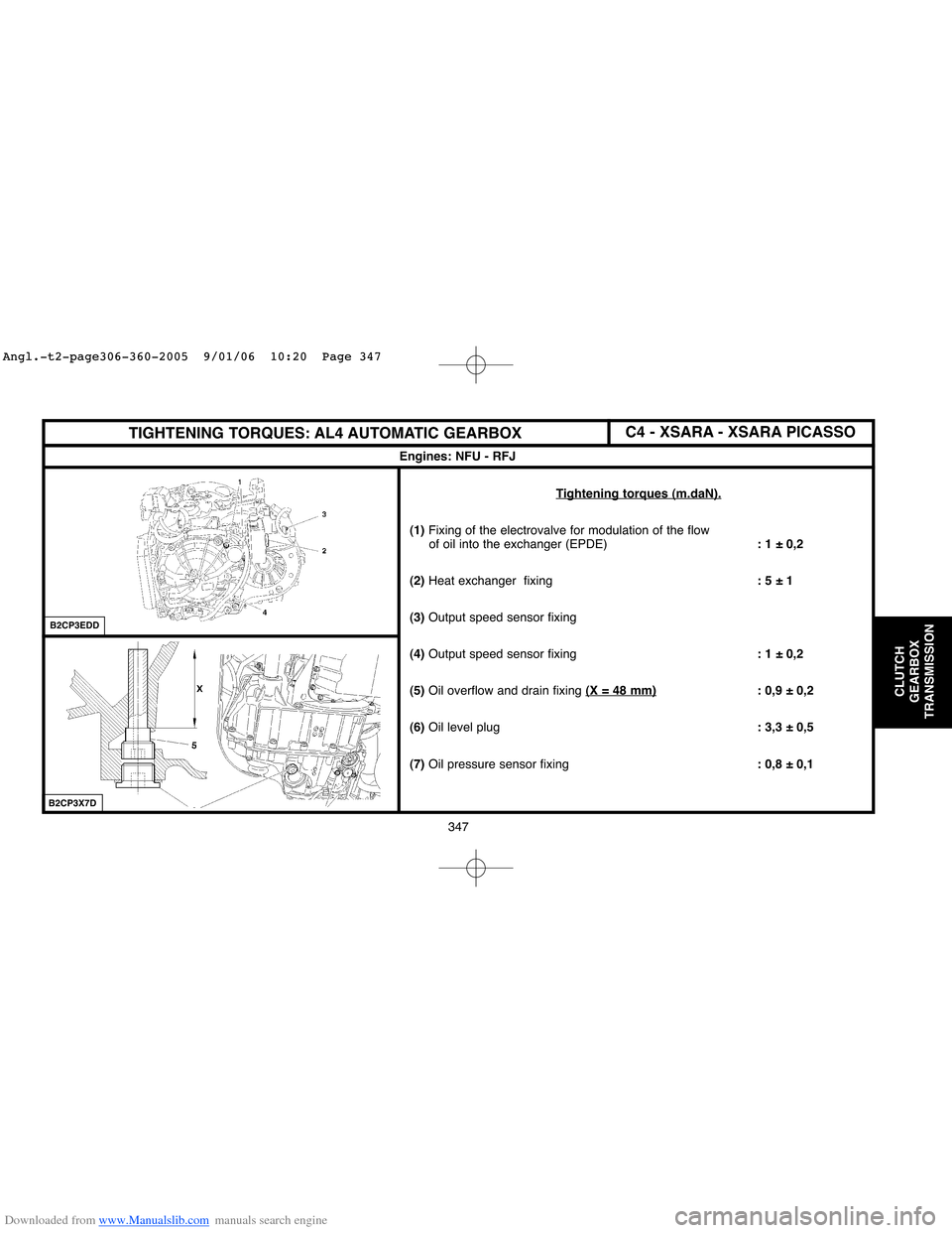
Tightening torques (m.daN).
(1) Fixing of the electrovalve for modulation of the flow
of oil into the exchanger (EPDE): 1 ± 0,2
(2)Heat exchanger fixing: 5 ± 1
(3) Output speed sensor fixing
(4)Output speed sensor fixing: 1 ± 0,2
(5)Oil overflow and drain fixing(X = 48 mm)
: 0,9 ± 0,2
(6)Oil level plug: 3,3 ± 0,5
(7)Oil pressure sensor fixing: 0,8 ± 0,1
C4 - XSARA - XSARA PICASSO
Angl.-t2-page306-360-2005 9/01/06 10:20 Page 347
Page 358 of 462
Downloaded from www.Manualslib.com manuals search engine 352
CLUTCH
GEARBOX
TRANSMISSION
AL4 GEARBOX CONTROLS
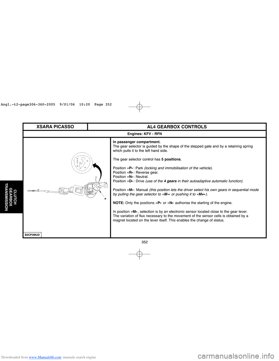
In passenger compartment.
The gear selector is guided by the shape of the stepped gate and by a retaining spring
which pulls it to the left hand side.
The gear selector control has 5 positions.
Position «P»: Park
(locking and immobilisation of the vehicle).
Position «R»: Reverse gear.
Position «N»: Neutral.
Position «D»: Drive
(use of the 4 gearsin their autoadaptive automatic function).
Position «M»: Manual (this position lets the driver select his own gears in sequential mode
by pulling the gear selector to «M-»or pushing it to «M+»).
NOTE:Only the positions «P»or «N»authorise the starting of the engine.
In position «M», selection is by an electronic sensor located close to the gear lever.
The variation of flux necessary to the movement of the sensor cells is obtained by a
magnet located on the lever itself. This enables the change of status.
Engines: KFV - RFN
XSARA PICASSO
B2CP3MUD
Angl.-t2-page306-360-2005 9/01/06 10:20 Page 352