head Citroen C4 2005 2.G Owner's Guide
[x] Cancel search | Manufacturer: CITROEN, Model Year: 2005, Model line: C4, Model: Citroen C4 2005 2.GPages: 462, PDF Size: 10.48 MB
Page 145 of 462

Downloaded from www.Manualslib.com manuals search engine 139
ENGINE
SPECIAL FEATURES - TIGHTENING TORQUES (m.daN)
Cylinder head
5 Camshaft bearing cap cover screws (*) 1 ± 0,1
6 Coolant outlet housing fixing 2 ± 0,2
Camshaft bearing cap cover studs (*)
7Pre-tightening (the 26 screws Ø 6)0,5
Tightening (the 26 screws Ø 6)1 ± 0,1
8 Inlet valve cover screws (*) (19 screws) 0,9 ± 0,1
Engine: RHR
B1DP1LCP
C4
Angl.-t2-page135-239-2005 9/01/06 10:13 Page 139
Page 146 of 462
Downloaded from www.Manualslib.com manuals search engine 140
ENGINESPECIAL FEATURES - TIGHTENING TORQUES (m.daN)
Engine: RHR
B1DP1LED
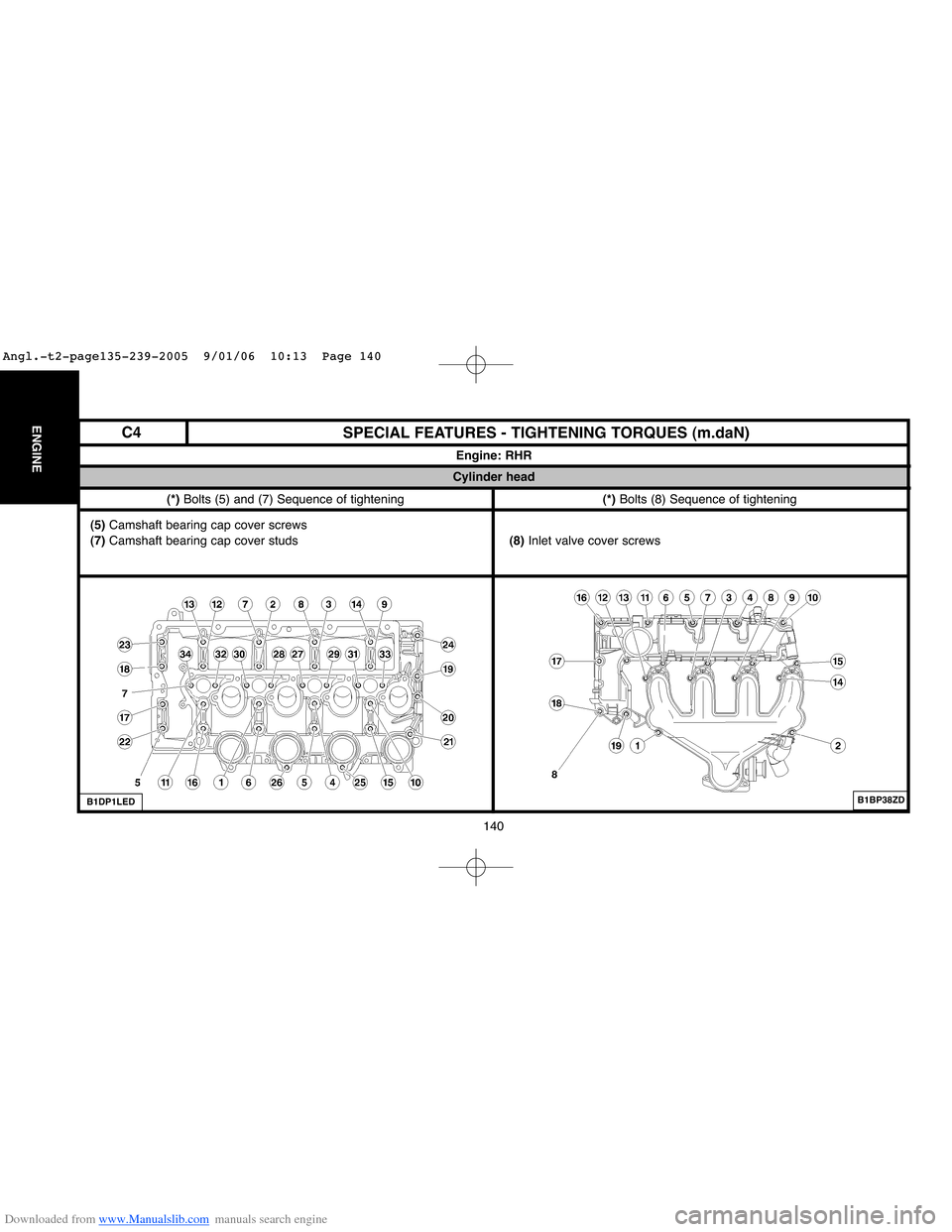
(*) Bolts (5) and (7) Sequence of tightening(*) Bolts (8) Sequence of tightening
Cylinder head
(5) Camshaft bearing cap cover screws
(7) Camshaft bearing cap cover studs(8) Inlet valve cover screws
B1BP38ZD
C4
Angl.-t2-page135-239-2005 9/01/06 10:13 Page 140
Page 154 of 462
Downloaded from www.Manualslib.com manuals search engine 148
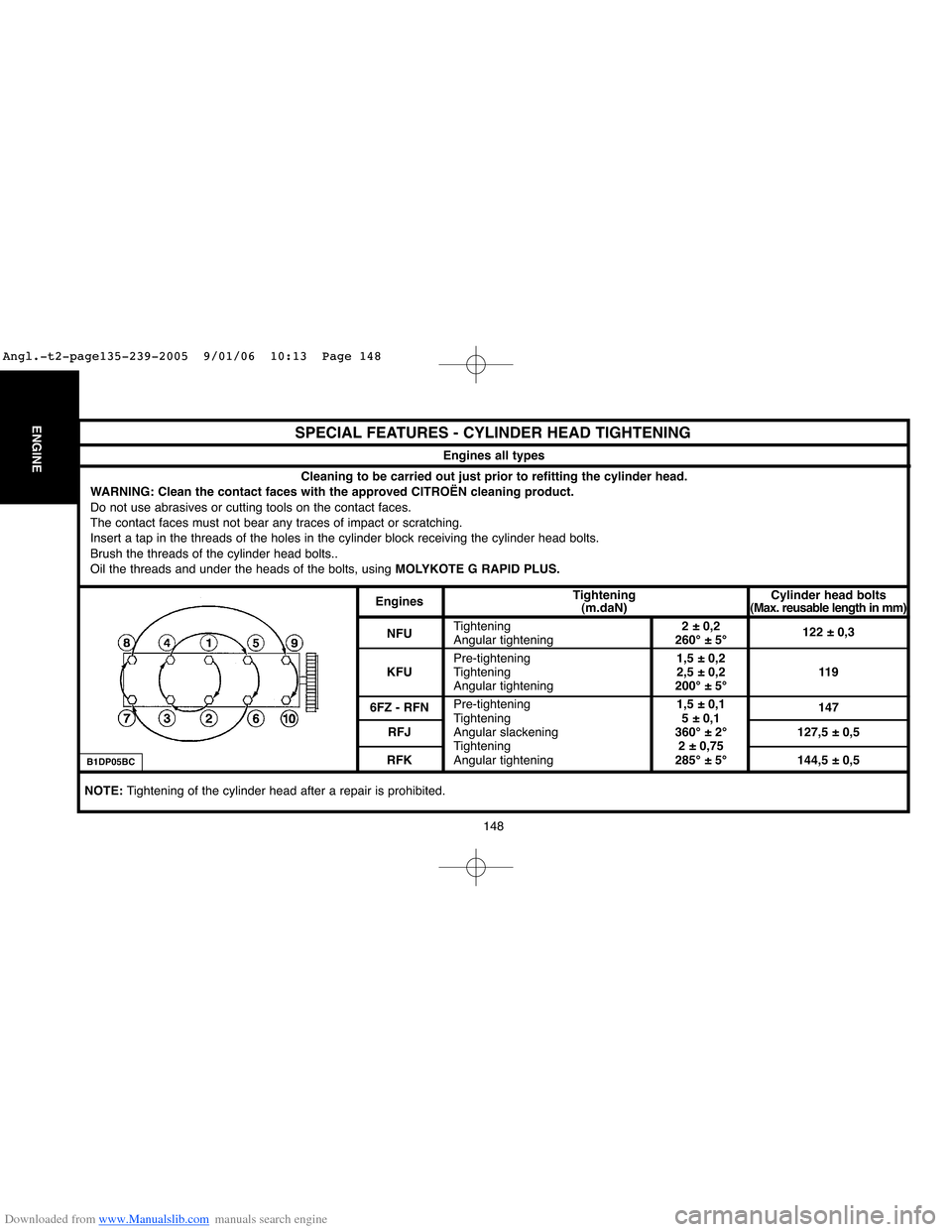
ENGINESPECIAL FEATURES - CYLINDER HEAD TIGHTENING
Engines all types
B1DP05BC
Cleaning to be carried out just prior to refitting the cylinder head.
WARNING: Clean the contact faces with the approved CITROËN cleaning product.
Do not use abrasives or cutting tools on the contact faces.
The contact faces must not bear any traces of impact or scratching.
Insert a tap in the threads of the holes in the cylinder block receiving the cylinder head bolts.
Brush the threads of the cylinder head bolts..
Oil the threads and under the heads of the bolts, usingMOLYKOTE G RAPID PLUS.
EnginesTightening Cylinder head bolts
(m.daN)(Max. reusable length in mm)
NFUTightening2 ± 0,2
Angular tightening260° ± 5°122 ± 0,3
Pre-tightening1,5 ± 0,2
KFUTightening2,5 ± 0,2 119
Angular tightening200° ± 5°
6FZ - RFNPre-tightening1,5 ± 0,1
147
Tightening5 ± 0,1
RFJAngular slackening360° ± 2° 127,5 ± 0,5
Tightening2 ± 0,75
RFKAngular tightening285° ± 5° 144,5 ± 0,5
NOTE: Tightening of the cylinder head after a repair is prohibited.
Angl.-t2-page135-239-2005 9/01/06 10:13 Page 148
Page 155 of 462
Downloaded from www.Manualslib.com manuals search engine 149
ENGINE
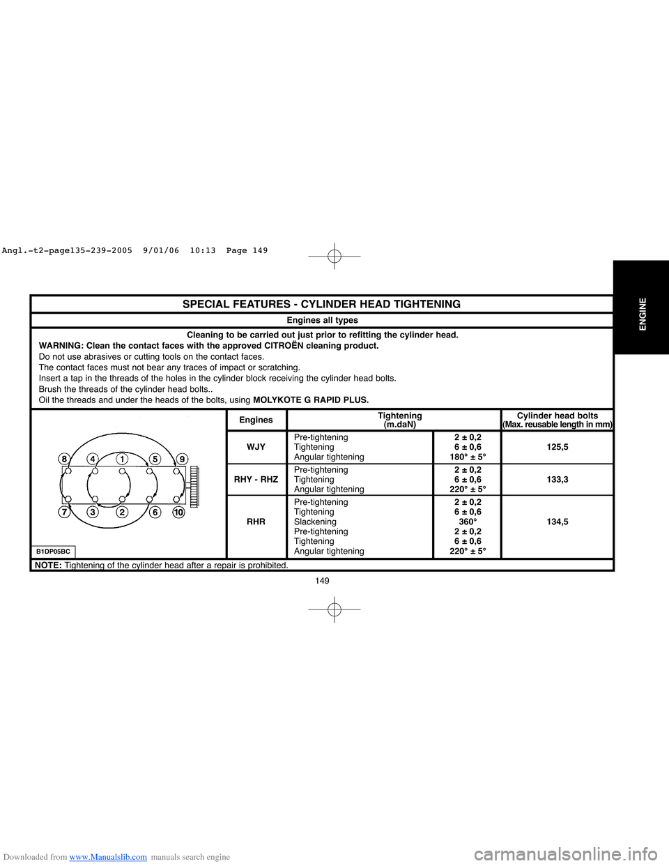
SPECIAL FEATURES - CYLINDER HEAD TIGHTENING
Engines all types
B1DP05BC
Cleaning to be carried out just prior to refitting the cylinder head.
WARNING: Clean the contact faces with the approved CITROËN cleaning product.
Do not use abrasives or cutting tools on the contact faces.
The contact faces must not bear any traces of impact or scratching.
Insert a tap in the threads of the holes in the cylinder block receiving the cylinder head bolts.
Brush the threads of the cylinder head bolts..
Oil the threads and under the heads of the bolts, using MOLYKOTE G RAPID PLUS.
EnginesTightening Cylinder head bolts
(m.daN)(Max. reusable length in mm)
Pre-tightening2 ± 0,2
WJYTightening6 ± 0,6 125,5
Angular tightening180° ± 5°
Pre-tightening2 ± 0,2
RHY - RHZTightening6 ± 0,6 133,3
Angular tightening220° ± 5°
Pre-tightening2 ± 0,2
Tightening6 ± 0,6
RHRSlackening360° 134,5
Pre-tightening2 ± 0,2
Tightening6 ± 0,6
Angular tightening220° ± 5°
NOTE: Tightening of the cylinder head after a repair is prohibited.
Angl.-t2-page135-239-2005 9/01/06 10:13 Page 149
Page 156 of 462
Downloaded from www.Manualslib.com manuals search engine 150
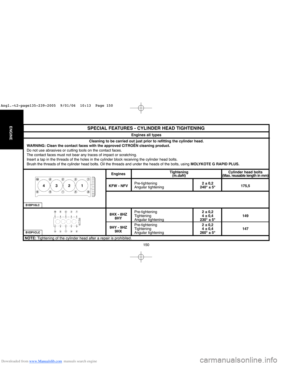
ENGINESPECIAL FEATURES - CYLINDER HEAD TIGHTENING
Engines all types
B1DP1CLC
Cleaning to be carried out just prior to refitting the cylinder head.
WARNING: Clean the contact faces with the approved CITROËN cleaning product.
Do not use abrasives or cutting tools on the contact faces.
The contact faces must not bear any traces of impact or scratching.
Insert a tap in the threads of the holes in the cylinder block receiving the cylinder head bolts.
Brush the threads of the cylinder head bolts. Oil the threads and under the heads of the bolts, using MOLYKOTE G RAPID PLUS.
EnginesTightening Cylinder head bolts
(m.daN)(Max. reusable length in mm)
Pre-tightening2 ± 0,2
KFW - NFV
Angular tightening240° ± 5°175,5
Pre-tightening2 ± 0,2
8HX - 8HZ
Tightening4 ± 0,4 149
8HY
Angular tightening230° ± 5°
Pre-tightening2 ± 0,2
9HY - 9HZ
Tightening4 ± 0,4 147
9HX
Angular tightening260° ± 5°
NOTE: Tightening of the cylinder head after a repair is prohibited.
B1BP10LC
Angl.-t2-page135-239-2005 9/01/06 10:13 Page 150
Page 214 of 462
Downloaded from www.Manualslib.com manuals search engine 208
ENGINECHECKING AND SETTING THE VALVE TIMING
Engine: RFJ
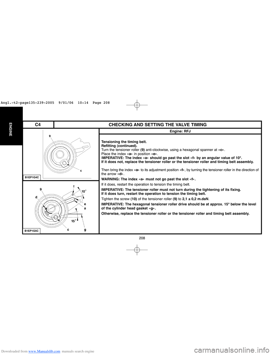
Tensioning the timing belt.
Refitting (continued).
Turn the tensioner roller (9)anti-clockwise, using a hexagonal spanner at «c».
Place the index «a»in position «e».
IMPERATIVE: The index «a» should go past the slot «f» by an angular value of 10°.
If it does not, replace the tensioner roller or the tensioner roller and timing belt assembly.
Then bring the index «a»to its adjustment position «f», by turning the tensioner roller in the direction of
the arrow «d».
WARNING: The index «a» must not go past the slot «f».
If it does, restart the operation to tension the timing belt.
IMPERATIVE: The tensioner roller must not turn during the tightening of its fixing.
If it does turn, restart the operation to tension the timing belt.
Tighten the screw (10)of the tensioner roller (9)to 2,1 ± 0,2 m.daN.
IMPERATIVE: The hexagonal tensioner roller drive should be at approx. 15° below the level
of the cylinder head gasket «g».
Otherwise, replace the tensioner roller or the tensioner roller and timing belt assembly.
B1EP1G4C
B1EP1G5C
C4
Angl.-t2-page135-239-2005 9/01/06 10:14 Page 208
Page 221 of 462
Downloaded from www.Manualslib.com manuals search engine 215
ENGINE
CHECKING AND SETTING THE VALVE TIMING
Engine: RFN
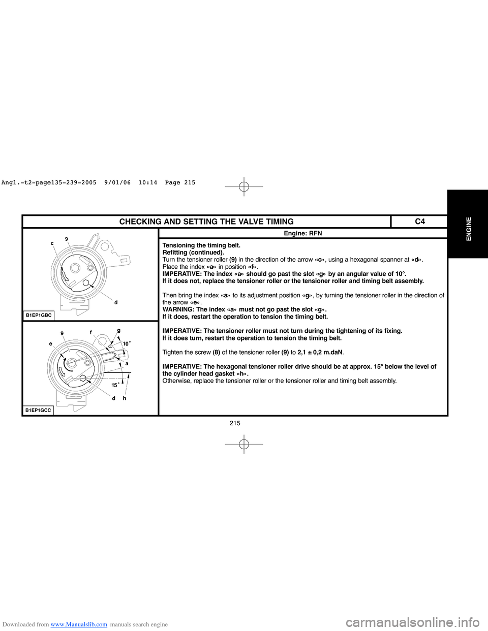
Tensioning the timing belt.
Refitting (continued).
Turn the tensioner roller (9)in the direction of the arrow «c», using a hexagonal spanner at «d».
Place the index «a»in position «f».
IMPERATIVE: The index «a» should go past the slot «g» by an angular value of 10°.
If it does not, replace the tensioner roller or the tensioner roller and timing belt assembly.
Then bring the index «a»to its adjustment position «g», by turning the tensioner roller in the direction of
the arrow «e».
WARNING: The index «a» must not go past the slot «g».
If it does, restart the operation to tension the timing belt.
IMPERATIVE: The tensioner roller must not turn during the tightening of its fixing.
If it does turn, restart the operation to tension the timing belt.
Tighten the screw (8)of the tensioner roller (9)to 2,1 ± 0,2 m.daN.
IMPERATIVE: The hexagonal tensioner roller drive should be at approx. 15° below the level of
the cylinder head gasket «h».
Otherwise, replace the tensioner roller or the tensioner roller and timing belt assembly.
B1EP1GBC
B1EP1GCC
C4
Angl.-t2-page135-239-2005 9/01/06 10:14 Page 215
Page 228 of 462
Downloaded from www.Manualslib.com manuals search engine 222
ENGINECHECKING AND SETTING THE VALVE TIMING
Engines: 6FZ - RFN
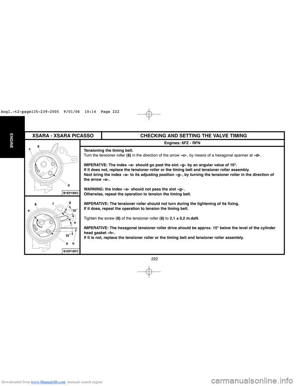
Tensioning the timing belt.
Turn the tensioner roller (8)in the direction of the arrow «c», by means of a hexagonal spanner at «d».
IMPERATVE: The index «a» should go past the slot «g» by an angular value of 10°.
If it does not, replace the tensioner roller or the timing belt and tensioner roller assembly.
Next bring the index «a» to its adjusting position «g», by turning the tensioner roller in the direction of
the arrow «e».
WARNING: the index «a» should not pass the slot «g».
Otherwise, repeat the operation to tension the timing belt.
IMPERATIVE: The tensioner roller should not turn during the tightening of its fixing.
If it does, repeat the operation to tension the timing belt.
Tighten the screw (9)of the tensioner roller (8)to 2,1 ± 0,2 m.daN.
IMPERATIVE: The hexagonal tensioner roller drive should be approx. 15° below the level of the cylinder
head gasket «h».
If it is not, replace the tensioner roller or the timing belt and tensioner roller assembly.
B1EP1BEC
B1EP1BFC
XSARA - XSARA PICASSO
Angl.-t2-page135-239-2005 9/01/06 10:14 Page 222
Page 236 of 462
Downloaded from www.Manualslib.com manuals search engine 230
ENGINECHECKING AND SETTING THE VALVE TIMING
Engine: RFK
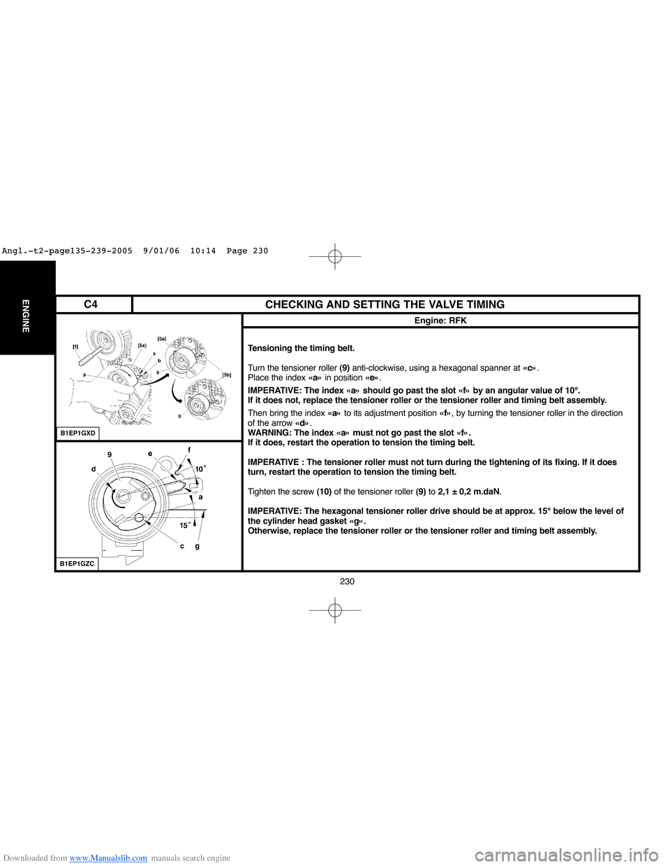
Tensioning the timing belt.
Turn the tensioner roller (9)anti-clockwise, using a hexagonal spanner at «c».
Place the index «a»in position «e».
IMPERATIVE: The index «a» should go past the slot «f» by an angular value of 10°.
If it does not, replace the tensioner roller or the tensioner roller and timing belt assembly.
Then bring the index «a»to its adjustment position «f», by turning the tensioner roller in the direction
of the arrow «d».
WARNING: The index «a» must not go past the slot «f».
If it does, restart the operation to tension the timing belt.
IMPERATIVE : The tensioner roller must not turn during the tightening of its fixing. If it does
turn, restart the operation to tension the timing belt.
Tighten the screw (10)of the tensioner roller (9)to 2,1 ± 0,2 m.daN.
IMPERATIVE: The hexagonal tensioner roller drive should be at approx. 15° below the level of
the cylinder head gasket «g».
Otherwise, replace the tensioner roller or the tensioner roller and timing belt assembly.
B1EP1GXD
B1EP1GZC
C4
Angl.-t2-page135-239-2005 9/01/06 10:14 Page 230
Page 277 of 462
![Citroen C4 2005 2.G Owners Guide Downloaded from www.Manualslib.com manuals search engine 271
ENGINE
CHECKING THE VALVE TIMING
Engine: RHR
Tools.
[1] Kit of plugs: (-).0188.T
[2] Double flywheel setting peg: (-).0188.X Toolkit 0188-T Citroen C4 2005 2.G Owners Guide Downloaded from www.Manualslib.com manuals search engine 271
ENGINE
CHECKING THE VALVE TIMING
Engine: RHR
Tools.
[1] Kit of plugs: (-).0188.T
[2] Double flywheel setting peg: (-).0188.X Toolkit 0188-T](/img/9/4138/w960_4138-276.png)
Downloaded from www.Manualslib.com manuals search engine 271
ENGINE
CHECKING THE VALVE TIMING
Engine: RHR
Tools.
[1] Kit of plugs: (-).0188.T
[2] Double flywheel setting peg: (-).0188.X Toolkit 0188-T
[3]Camshaft setting peg: (-).0188.M
IMPERATIVE: Respect the safety and cleanliness requirements specific to High pressure Diesel
injection (HDi) engine versions.
Remove the engine cover and the battery.
Disconnect the negative terminal of the battery.
Raise and support the front of the vehicle.
Remove the under-engine sound-deadening and the front RH splash-shield.
Uncouple, plug and move aside, using tool [1], the fuel supply and fuel return pipes..
Suspend the engine, using a workshop hoist.
Remove the engine support bracket and the engine support.
Move aside the electrical harness (1).
Remove:
- The camshaft position sensor.
- The inlet cylinder head cover (2).
- The upper timing cover screws.
- The upper timing cover (3).
B1EP1GFC
C4
Angl.-t2-page240-282-2005 9/01/06 10:16 Page 271