socket Citroen C4 PICASSO 2015 2.G Owner's Manual
[x] Cancel search | Manufacturer: CITROEN, Model Year: 2015, Model line: C4 PICASSO, Model: Citroen C4 PICASSO 2015 2.GPages: 420, PDF Size: 10.72 MB
Page 108 of 420

106
Front fittings
1. Sun visor.
2. C ard holder.
3.
G
love box.
4.
C
entral
s
torage.
I
t contains the power and audio sockets.
5.
R
aised console with closed storage, low
c
onsole or removable console.
6.
C
up holder.
7.
D
oor pockets.
8.
S
torage below the steering wheel.
(
Handbook pack).
Comfort
Page 111 of 420

109
Central storage compartment
F To open the central storage compartment, p
ull the grip and lower the cover.
It
is illuminated on opening.
A
button on the upper part allows the lighting to
b
e deactivated.
Depending
on equipment, it may contain:
-
o
ne 12 V socket,
-
o
ne or two USB ports,
-
o
ne auxiliary socket
12 V accessory socket
F To connect a 12 V accessory (maximum p
ower: 120 Watts), lift the cover and
c
onnect a suitable adaptor.
Do
not exceed the maximum power
r
ating of the socket (risk of damage to
y
our device). The
auxiliary socket is located in the central s
torage box.
It
permits the connection of a portable device,
s
uch as a digital audio player of the iPod
® type,
to
listen
to
your
music
files
using
the
vehicle's
s
peakers.
The
management
of
the
files
is
done
using your
p
ortable
d
evice.
Auxiliary socket
For more information on the use of this e quipment, refer to the "Audio and telematics"
s
ection.
3
Comfort
Page 116 of 420

114
Side blindsStorage wells
There are two storage wells under the rear p
assengers' f eet.
To
open them, lift the cover at the cutout.Fitted to the windows for the 2nd row seats, they protect
the
passenger
compartment
from the sun's rays.
F Pull the tab A and anchor the blind on the h
ook B.
12 V accessory socket
F To connect a 12 V accessory (maximum p
ower: 120 Watts), lift the cover and
c
onnect a suitable adaptor.
Do
not exceed the maximum power
r
ating of the socket (risk of damage to
y
our device).
Comfort
Page 117 of 420

115
Boot fittings
1. Rear parcel shelf (see details on a following page)
2.
H
ooks
(
see details on a following page)
3.
To r c h
(
see details on a following page)
4.
St
orage
b
oxes
(
see details on a following page)
5.
St
orage
n
et
6.
L
ashing eyes
7.
1
2 V socket (maximum power: 120 Watts)
Versions
with storage boxes: these
b
oxes must be put in place before
l
oading the boot.
3
Comfort
Page 119 of 420

117
Boot fittings
1. Luggage cover blind (
see details on a following page)
2.
T
o r c h
(
see details on a following page)
3.
C
oncertina
b
oards
4.
1
2 V socket (maximum power: 120 Watts)
5.
A
rm rest with cup holder and storage
spa
ce
6.
R
etaining
s
traps
7.
L
ocation for stowing the luggage cover
b
lind
8.
O
pen
s
torage
9.
L
ower lashing eyes
10.
U
pper eyes (fixings for the boot net)
The
boot net fixing eyes 10,
located
a
t the level of the parcel shelf, are not
intended
for lashing loads or securing
l
uggage.
3
Comfort
Page 253 of 420

251
A. "Sealant" or "Air" position selector.
B. on "
I" / off "O" s witch.
C.
D
eflation button.
D.
P
ressure gauge (in bar and psi).
E.
C
ompartment
h
ousing:
-
a
cable with adaptor for 12 V socket,
-
v
arious inflation adaptors for
a
ccessories, such as balls,
bicycle tyres...
Description of the kit
The speed limit sticker I must be affixed t o the vehicle's steering wheel to remind
y
ou that a wheel is in temporary use.
Do
not exceed a speed of 50 mph
(
80 km/h) when driving with a tyre
r
epaired using this type of kit.
F.
S
ealant
c
artridge.
G.
W
hite pipe with cap for repair.
H.
B
lack pipe for inflation.
I.
S
peed limit sticker.
The
tyre
inflation
pressures
are
given
on
this
lab
el.
The
vehicle's
electric
system
allows
the
c
onnection
of
a
compressor
for
long
e
nough
to
inflate
a
tyre
after
a
puncture
r
epair
or
for
inflating
a
small
inflatable
a
ccessory.
7
Practical information
Page 254 of 420

252
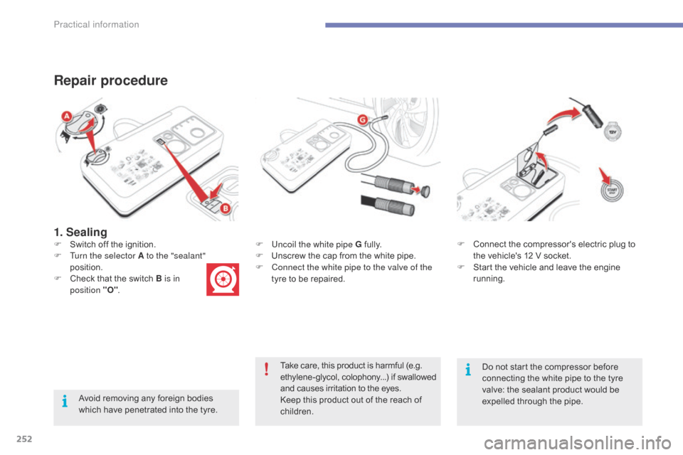
1. Sealing
Repair procedure
Avoid removing any foreign bodies which have penetrated into the tyre.F
U
ncoil the white pipe G
f
ully.
F
U
nscrew the cap from the white pipe.
F
C
onnect the white pipe to the valve of the
tyre to be repaired.
F
S
witch off the ignition.
F
T
urn the selector A to the "sealant"
position.
F
C
heck that the switch B is in
position "O" . F
C
onnect the compressor's electric plug to
t
he vehicle's 12 V socket.
F
S
tart the vehicle and leave the engine
r
unning.
Take care, this product is harmful (e.g.
e
thylene-glycol, colophony...) if swallowed
a
nd causes irritation to the eyes.
Keep this product out of the reach of
c
hildren.Do
not start the compressor before
c
onnecting the white pipe to the tyre v
alve: the sealant product would be e
xpelled through the pipe.
Practical information
Page 256 of 420

254
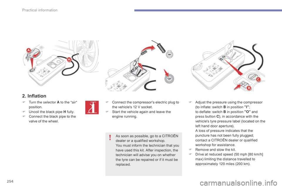
2. Inflation
F Turn the selector A to the "air" position.
F
U
ncoil the black pipe H
f
ully.
F
C
onnect the black pipe to the
v
alve of the wheel. F
C onnect the compressor's electric plug to t
he vehicle's 12 V socket.
F
S
tart the vehicle again and leave the
e
ngine
r
unning.
As
soon as possible, go to a CITROËN
d
ealer or a qualified workshop.
You
must inform the technician that you
h
ave used this kit. After inspection, the
t
echnician will advise you on whether
t
he tyre can be repaired or if it must be
r
eplaced.F
A djust the pressure using the compressor (
to inflate: switch B in position "I";
t
o deflate: switch B in position "O"
and
p
ress button C),
in accordance with the
v
ehicle's
t
yre pressure label (located on the
l
eft hand door aperture).
A
loss of pressure indicates that the
p
uncture has not been fully plugged;
c
ontact a CITROËN dealer or qualified
w
orkshop for assistance.
F
R
emove and stow the kit.
F
D
rive at reduced speed (50 mph [80 km/h]
m
ax) limiting the distance travelled to
a
pproximately 120 miles (200 km).
Practical information
Page 258 of 420

256
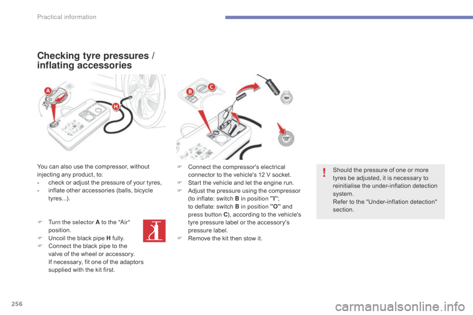
Checking tyre pressures /
inflating accessories
You can also use the compressor, without injecting any product, to:
-
c
heck or adjust the pressure of your tyres,
-
i
nflate other accessories (balls, bicycle
t
yres...).
F
T
urn the selector A to the "
ai
r"
position.
F
U
ncoil the black pipe H
f
ully.
F
C
onnect the black pipe to the
v
alve of the wheel or accessory.
I
f necessary, fit one of the adaptors
s
upplied with the kit first. F
C onnect the compressor's electrical
c
onnector to the vehicle's 12 V socket.
F
S
tart the vehicle and let the engine run.
F
A
djust the pressure using the compressor
(
to inflate: switch B in position "I";
t
o deflate: switch B in position "O"
and
p
ress button C),
according to the vehicle's
t
yre pressure label or the accessory's
p
ressure label.
F
R
emove the kit then stow it.Should
the pressure of one or more
t
yres be adjusted, it is necessary to
r
einitialise the under-inflation detection
s
ystem.
Refer
to the "Under-inflation detection"
s
ection.
Practical information
Page 265 of 420

263
Removing a wheel
Parking the vehicle
Immobilise the vehicle where it does not block traffic: the ground must be level,
s
table and not slippery.
Apply
the parking brake unless it has
b
een programmed to automatic mode,
s
witch off the ignition and engage first
g
ear* to block the wheels.
Check
that the braking warning lamp
a
nd the P warning lamp in the parking
b
rake control lever come on.
For
greater safety, place the chock 2
against
the wheel opposite to the one
b
eing
c
hanged.
The
occupants must get out of the
v
ehicle and wait where they are safe.
Never
go underneath a vehicle raised
u
sing a jack; use an axle stand.
List of operations
F Remove the finisher from from each o
f bolts using the tool 4 (depending on
e
quipment).
F
F
it the security socket 5 on the
wheelbrace
1 to slacken the security bolt
(
if fitted).
F
S
lacken the other bolts (no more than a
1
/4 turn) using the wheelbrace 1
o
n l y.
*
Position R
for
an
electronic
gearbox
or
P for
an
automatic
gearbox. Do
not use:
-
t
he jack for any purpose other than
l
ifting the vehicle,
-
a
ny other jack than the one
s
upplied by the manufacturer.
7
Practical information