towing Citroen C4 PICASSO RHD 2015 1.G User Guide
[x] Cancel search | Manufacturer: CITROEN, Model Year: 2015, Model line: C4 PICASSO RHD, Model: Citroen C4 PICASSO RHD 2015 1.GPages: 428, PDF Size: 10.09 MB
Page 194 of 428

192
The system is deactivated by pressing the control.
The
system is deactivated automatically:
-
o
n switching off the ignition,
-
i
f the engine stalls,
-
i
f no manoeuvre is started within 5 minutes
o
f selection of the type of manoeuvre,
-
a
fter a prolonged stop of the vehicle during
a
manoeuvre,
-
i
f the road wheel anti-slip regulation (ASR)
i
s
t
riggered,
-
i
f the speed of the vehicle exceeds the
s
tated limit,
-
w
hen the driver interrupts movement of the
s
teering
w
heel,
-
a
fter 4 manoeuvre cycles,
-
o
n opening the driver's door,
-
i
f one of the front wheels encounters an
o
bstacle.
The
operation indicator lamp goes off in the
i
nstrument panel and a message is displayed
a
ccompanied by an audible signal.
The
driver should then take back control of the
v
ehicle's
s
teering.
Deactivation
The system is switched off automatically:
- w hen towing a trailer,
-
i
f the driver's door is opened,
-
i
f the speed of the vehicle is above 42 mph
(
70 km/h).
To
switch the system of for a prolonged period,
c
ontact a CITROËN dealer or a qualified
w
orkshop.
In the event of a fault with the system, this warning lamp is displayed in the i
nstrument panel and a message appears,
a
ccompanied by an audible signal.
Operating faults
In the event of a fault, the symbol for the button changes to alert
m
ode and the warning lamp flashes
f
or a few moments then goes off.
Contact
a
CITROËN dealer or a qualified
w
orkshop.
Switching off
If the lateral distance between your vehicle a nd the space is too great, the system may n
ot be able to measure the space.
Anything
projecting beyond the envelope
o
f the vehicle (long or wide load) is not
t
aken into account by the Park Assist
s
ystem during a manoeuvre.
In
bad weather or in winter, ensure that
t
he sensors are not covered by road
d
irt, ice or snow.
In
the event of a fault, have the system
c
hecked by a CITROËN dealer or a
q
ualified
w
orkshop.
If
the
system
is
deactivated
during
a
m
anoeuvre,
the
drive
should
reactivate
i
t
to
repeat
the
measurement. The
indicator
lamp
for
the
function
f
lashes
for
a
few
seconds.
If
the
fault
occurs
during
the
use
of
t
he
system,
the
indicator
lamp
goes
o
f f.
Driving
Page 215 of 428

213
Direction indicators
F Left: lower the lighting stalk passing the p
oint of resistance.
F
R
ight: raise the lighting stalk passing the
p
oint of resistance.
Three flashes of the direction
indicators
F Press briefly upwards or downwards, w
ithout going beyond the point of
r
esistance; the direction indicators will
f
lash 3 times.
Hazard warning lam ps
A visual warning by means of the direction i
ndicators to alert other road users to a vehicle
b
reakdown, towing or accident.
F
P
ress this button, the direction indicators
f
lash.
They
can operate with the ignition off.
Automatic operation of
hazard warning lamps
When braking in an emergency, depending on the deceleration, the hazard warning lamps
c
ome on automatically.
They
switch off automatically the first time you
a
ccelerate.
F
Y
ou can also switch them off by pressing
t
he button.
Horn
F Press the central part of the steering wheel.
6
Safety
Page 216 of 428
214
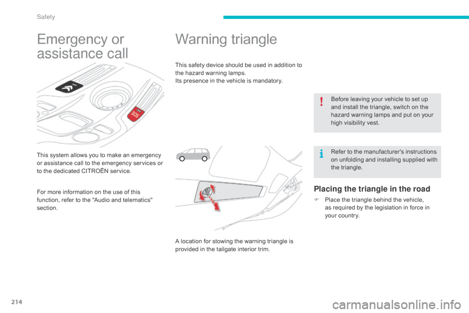
This system allows you to make an emergency or assistance call to the emergency services or
t
o the dedicated CITROËN service.
Emergency or
a
ssistance call
For more information on the use of this f
unction, refer to the "Audio and telematics"
s
ection.
Warning triangle
This safety device should be used in addition to the hazard warning lamps.
Its
presence in the vehicle is mandatory.
A
location for stowing the warning triangle is
p
rovided in the tailgate interior trim.
Placing the triangle in the road
F Place the triangle behind the vehicle, a
s required by the legislation in force in
y
our country.Before
leaving your vehicle to set up
a
nd install the triangle, switch on the
h
azard warning lamps and put on your
h
igh visibility vest.
Refer to the manufacturer's instructions
o
n unfolding and installing supplied with
t
he triangle.
Safety
Page 225 of 428

223
2nd row seat belts
Fastening
F Pull the strap, then insert the tongue in the buc
kle.
F
C
heck that the seat belt is fastened
c
orrectly by pulling the strap.
Unfastening
F Press the red button on the buckle.
F G uide the seat belt as it reels in.The
rear seats are each fitted with a seat belt,
t
hree-point anchorages with inertia reel and
f
orce limiter (except for the centre rear seat).
Guide the belt as it reels in and place the
t
ongue on the magnet at the side anchorage
po
int.
2nd row outer seat belts
(stowing)
6
Safety
Page 226 of 428

224
2nd row centre seat belt
The seat belt for the centre rear seat is built into the roof.
Fastening
F Pull the strap and insert the tongue A into
the right hand buckle.
F
I
nsert tongue B into the left hand buckle.
F
C
heck that each buckle is correctly
f
astened by pulling on the belt webbing.
Unfastening
F Press the red button in buckle B, then
buckle A .
F
G
uide the seat belt as it reels in and place
t
he tongue B and then A on the magnet in
t
he roof anchorage point.
be
fore any operation of the rear seats,
to
avoid damage to the seat belts
c
heck that there is no slack in the outer
b
elts and secure their tongues on the
a
nchorage points. The centre seat belt
m
ust be fully reeled in.
3rd row seat belts
Fastening
F Detach the seat belt strap from its retaining l
oop located on the side trim of the boot.
F
P
ull on the strap and insert the tongue into
t
he buckle.
F
C
heck that the buckle is correctly fastened
b
y pulling on the belt strap.
Unfastening and stowing
F Press the red button in buckle.
F G uide the seat belt strap as it reels in.
F
S
ecure the strap, flat in the retaining loop.
Ensure that the the seat belts are
secured
when not in use.
Safety
Page 256 of 428

254
List of tools
* Depending on equipment.
al
l of these tools are specific to your vehicle
and can vary according to equipment. Do not
u
se them for other purposes.
1.
1
2 V compressor.
C
ontains a sealant cartridge for the
t
emporary repair of a tyre and can also be
u
sed for adjusting tyre pressures.
2.
C
hocks* to immobilise the wheels of the
v
ehicle.
3.
B
olt cover removal tool*.
F
or removing the wheel bolt finishers
(
covers) on alloy wheels.
4.
R
emovable towing eye.
S
ee the "Towing the vehicle" section.
Practical information
Page 265 of 428
263
* Depending on version. The complete tooling i
s with the spare wheel.
Changing a wheelProcedure for changing a wheel with a punctured tyre by the spare wheel using the tools provided with the vehicle.
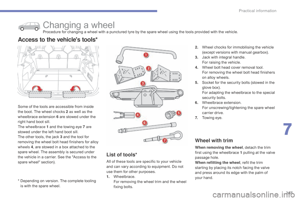
S
ome
of
the
tools are accessible from inside
t
he
boot.
The
wheel chocks 2 as well as the
wheelbrace
extension 6 are stowed under the
r
ight
hand
boot sill.
The wheelbrace 1
and the towing eye 7 are
stowed
under
the left hand boot sill.
The
other
tools, the jack 3 and the tool for
r
emoving
the
wheel bolt head finishers for alloy
w
heels 4 ,
are
stowed in a box attached to the
s
pare
wheel.
The assembly is secured under
t
he
vehicle
in
a carrier. See the "Access to the
s
pare
wheel"
section).
Access to the vehicle's tools*
2. Wheel chocks for immobilising the vehicle (
except versions with manual gearbox).
3.
J
ack with integral handle.
F
or raising the vehicle.
4.
W
heel bolt head cover removal tool.
F
or removing the wheel bolt head finishers
o
n alloy wheels.
5.
S
ocket for the security bolts (stowed in the
g
love box).
F
or adapting the wheelbrace to the special
s
ecurity bolts.
6.
W
heelbrace
e
xtension.
F
or unscrewing/tightening the spare wheel
c
arrier drive.
7.
T
owing eye.
Wheel with trim
When removing the wheel , detach the trim f
irst using the wheelbrace 1 pulling at the valve
p
assage hole.
When refitting the wheel ,
refit the trim
s
tarting by placing its notch facing the valve
a
nd press around its edge with the palm of
y
our hand.
List of tools*
all of these tools are specific to your vehicle
and can vary according to equipment. Do not
u
se them for other purposes.
1.
W
heelbrace.
F
or removing the wheel trim and the wheel
f
ixing
bol
ts.
7
Practical information
Page 267 of 428
265
A puncture wheel from the vehicle cannot be fitted under the vehicle. It
m
ust
b
e
c
arried
i
n
t
he
b
oot.
U
se
a
c
over
t
o protect the boot.
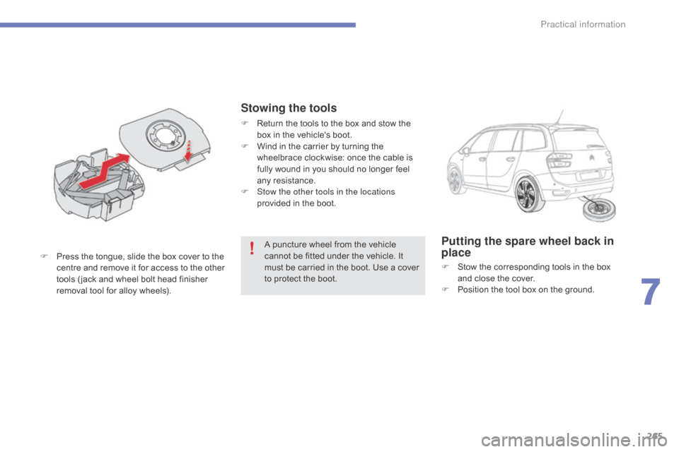
F
P
ress
the
tongue,
slide
the
box
cover
to
the
c
entre
a
nd
r
emove
i
t
f
or
a
ccess
t
o
t
he
o
ther
t
ools
( jack
and
wheel
bolt
head
finisher
r
emoval
tool
for
alloy
wheels).Putting the spare wheel back in
place
F Stow the corresponding tools in the box a
nd close the cover.
F
P
osition the tool box on the ground.
Stowing the tools
F Return the tools to the box and stow the b
ox in the vehicle's boot.
F
W
ind in the carrier by turning the
w
heelbrace clockwise: once the cable is
f
ully wound in you should no longer feel
an
y
r
esistance.
F
S
tow the other tools in the locations
provided
in the boot.
7
Practical information
Page 295 of 428
293
Towing the vehicle
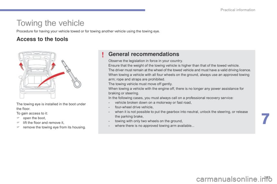
The towing eye is installed in the boot under the floor.
To
gain access to it:
F
o
pen the boot,
F
l
ift the floor and remove it,
F
r
emove the towing eye from its housing.
General recommendations
Observe the legislation in force in your country.
E nsure that the weight of the towing vehicle is higher than that of the towed vehicle.
The
driver must remain at the wheel of the towed vehicle and must have a valid driving licence.
When
towing a vehicle with all four wheels on the ground, always use an approved towing
a
rm; rope and straps are prohibited.
The
towing vehicle must move off gently.
When
towing a vehicle with the engine off, there is no longer any power assistance for
b
raking or steering.
In
the following cases, you must always call on a professional recovery service:
-
v
ehicle broken down on a motor way or fast road,
-
f
our-wheel drive vehicle,
-
w
hen it is not possible to put the gearbox into neutral, unlock the steering, or release
t
he parking brake,
-
t
owing with only two wheels on the ground,
-
w
here there is no approved towing arm available...
Procedure
for
having
your
vehicle
towed
or
for
towing
another vehicle using the towing eye.
Access to the tools
7
Practical information
Page 296 of 428

294
Towing another vehicle
F On the rear bumper, unclip the cover by p
ressing at the bottom.
F
S
crew the towing eye in fully.
F
I
nstall the towing bar.
F
S
witch on the hazard warning lamps on
b
oth vehicles.
F
M
ove off gently, drive slowly and for a short
di
stance.
F
O
n
the
front
bumper,
unclip
the
cover
by
p
ressing
on
the
left.
F
S
crew
the
towing
eye
in
fully.
F
I
nstall
the
towing
bar.
F
P
lace
the
gear
lever
in
neutral
(position
N
on
an
electronic
or
automatic
gearbox).
Towing your vehicle
Failure to observe this instruction could r esult in damage to certain components
(
braking, transmission...) and the
a
bsence of braking assistance the next
t
ime the engine is started.
F
U
nlock the steering by turning the key
i
n
the ignition one notch and release the
par
king
b
rake.
F
S
witch on the hazard warning lamps on
b
oth vehicles.
F
M
ove off gently, drive slowly and for a short
di
stance.
Practical information