boot Citroen C5 2016 (RD/TD) / 2.G Owner's Guide
[x] Cancel search | Manufacturer: CITROEN, Model Year: 2016, Model line: C5, Model: Citroen C5 2016 (RD/TD) / 2.GPages: 366, PDF Size: 30.93 MB
Page 96 of 366

94
C5_en_Chap03_ergo-et-confort_ed01-2015
High load retaining net
(Tourer)
Hooked onto the special upper and lower
fixings, this permits use of the entire loading
volume up to the roof:
- behind the rear seats (row 2),
- behind the front seats (row 1) when the rear
seats are folded.
When positioning the net, check that the strap
loops are visible from the boot; this will make
slackening or tightening easier.
Installation
F Fold down the backrests of the rear seats.
F Position the high load retaining net roller
above the two rails 1 located behind the
rear seats (2/3 bench seat). The two
notches 2 must be placed above the
two rails. F
Slide the two rails 1 into the notches 2 and
push the roller (lengthways) from right to
left to secure it.
F Reposition the rear seat backrests.
Ease of use and comfort
Page 174 of 366
172
C5_en_Chap07_securite-enfant_ed01-2015
"ISOFIX" mountings
Your vehicle has been approved in accordance
with the latest ISOFIX regulations.
The outer rear seats are fitted with regulation
ISOFIX mountings.
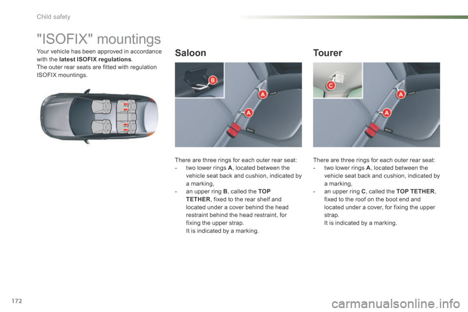
There are three rings for each outer rear seat:
- two lower rings A , located between the
vehicle seat back and cushion, indicated by
a marking,
- an upper ring B , called the TOP
TETHER , fixed to the rear shelf and
located under a cover behind the head
restraint behind the head restraint, for
fixing the upper strap.
It is indicated by a marking. There are three rings for each outer rear seat:
-
two lower rings A , located between the
vehicle seat back and cushion, indicated by
a marking,
- an upper ring C , called the TOP TETHER ,
fixed to the roof on the boot end and
located under a cover, for fixing the upper
strap.
It is indicated by a marking.Saloon Tourer
Child safety
Page 183 of 366
181
C5_en_Chap08_information_ed01-2015
Temporary puncture repair kit
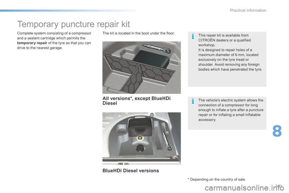
The kit is located in the boot under the floor.
Complete system consisting of a compressor
and a sealant cartridge which permits the
temporary repair of the tyre so that you can
drive to the nearest garage. This repair kit is available from
CITROËN dealers or a qualified
workshop.
It is designed to repair holes of a
maximum diameter of 6 mm, located
exclusively on the tyre tread or
shoulder. Avoid removing any foreign
bodies which have penetrated the tyre.
The vehicle's electric system allows the
connection of a compressor for long
enough to inflate a tyre after a puncture
repair or for inflating a small inflatable
accessory.
All versions*, except BlueHDi
Diesel
BlueHDi Diesel versions
* Depending on the country of sale.
8
Practical information
Page 188 of 366

186
C5_en_Chap08_information_ed01-2015
Access to the spare wheel
Removing the boot floor
F Saloon: raise the boot floor and fold in two.
F Tourer : raise the boot floor and hook it
using the retractable handle. Secure the
hook to the top part of the boot.
Removing the standard spare
wheel
F d etach the strap then push the wheel
for wards so as to be able to lift it.
Repositioning the standard spare
wheel
F Position the spare wheel flat in the boot,
then pull it towards you.
F Next place the toolbox inside the wheel,
then secure the assembly using the strap.
Removing the "space-saver"
spare wheel
F Unscrew the central yellow screw.
F Take the spare wheel from the rear and lift
it towards you.
F Remove the wheel from the boot.
Practical information
Page 189 of 366
187
C5_en_Chap08_information_ed01-2015
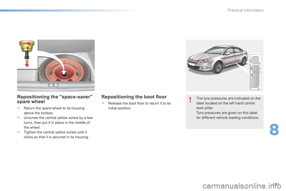
The tyre pressures are indicated on the
label located on the left hand centre
door pillar.
Tyre pressures are given on this label
for different vehicle loading conditions.Repositioning the "space-saver"
spare wheel
F Return the spare wheel to its housing
above the toolbox.
F Unscrew the central yellow screw by a few
turns, then put it in place in the middle of
the wheel.
F Tighten the central yellow screw until it
clicks so that it is secured in its housing.
Repositioning the boot floor
F Release the boot floor to return it to its
initial position.
8
Practical information
Page 199 of 366
197
C5_en_Chap08_information_ed01-2015
Rear lamps (Saloon)
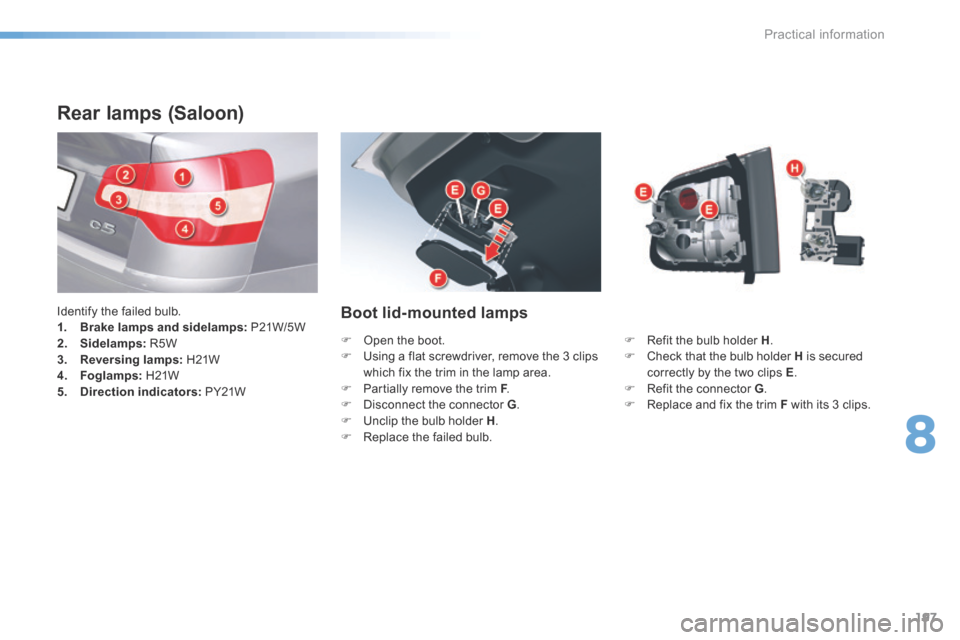
Identify the failed bulb.
1. Brake lamps and sidelamps: P21W/5 W
2. Sidelamps: R5W
3. Reversing lamps: H21W
4. Foglamps: H21W
5. Direction indicators: PY21WBoot lid-mounted lamps
F Refit the bulb holder H .
F Check that the bulb holder H is secured
correctly by the two clips E .
F Refit the connector G .
F Replace and fix the trim F with its 3 clips.
F
Open the boot.
F Using a flat screwdriver, remove the 3 clips
which fix the trim in the lamp area.
F Partially remove the trim F .
F d isconnect the connector G .
F Unclip the bulb holder H .
F Replace the failed bulb.
8
Practical information
Page 200 of 366

198
C5_en_Chap08_information_ed01-2015
Wing-mounted lamps
F Remove the lateral boot trim flap A . To do
so, pull it towards the inside of the boot,
then pull it upwards.
F d isconnect connector B .
F Unscrew the 2 fixings C .
F Remove the lamp from its housing. F d
etach the bulb holder D .
F Replace the failed bulb.
F Refit the bulb holder D .
F Place the lamp in its housing.
F Screw in the 2 fixings C .
F Refit connector B .
F Refit the side boot trim A .
For vehicles fitted with a Hi-Fi amplifier, on the
right hand side slacken the screw by a quarter
turn, then pull the boot side trim A up. You can use the wheelbrace to screw or
unscrew the fixings C
.
Practical information
Page 201 of 366

199
C5_en_Chap08_information_ed01-2015
Tailgate-mounted lamps
Rear lamps (Tourer)
Identify the failed bulb.
1. Brake lamps and sidelamps: P21W/5 W
2. Sidelamps: R5W
3. Reversing lamps: H21W
4. Foglamps: H21W
5. Direction indicators: PY21W F
Refit the bulb holder H ensuring that it is
correctly clipped in place.
F Position the lamp in its housing.
F Tighten the fixing nut G .
F Refit the connector F .
F Position and clip in place the plastic
cover E .
F
Open the boot.
F Using a flat screwdriver, remove the plastic
cover E .
F d isconnect the connector F .
F Unscrew the fixing nut G .
F Disengage the lamp from its housing.
F Unclip the bulb holder H .
F Replace the failed bulb.
You can use the wheelbrace to screw or
unscrew the fixing nut G.
8
Practical information
Page 202 of 366

200
C5_en_Chap08_information_ed01-2015
Wing-mounted lamps
F Pull away the flap in the boot side trim A .
To do this, pull it towards the middle of the
boot, then pull it up.
F d isconnect the connector B .
F Unscrew the fixing nut C .
F Remove the lamp from its housing. F d
etach the bulb holder D .
F Replace the faulty bulb.
F Refit the bulb holder D .
F Place the lamp in its housing.
F Screw in the fixing nut C .
F Refit the connector B .
F Refit the side boot trim A .
For vehicles fitted with a Hi-Fi amplifier, on the
right hand side slacken the screw by a quarter
turn, then pull the boot side trim A up. You can use the wheelbrace to screw or
unscrew the fixing nut C
.
Practical information
Page 204 of 366
202
C5_en_Chap08_information_ed01-2015
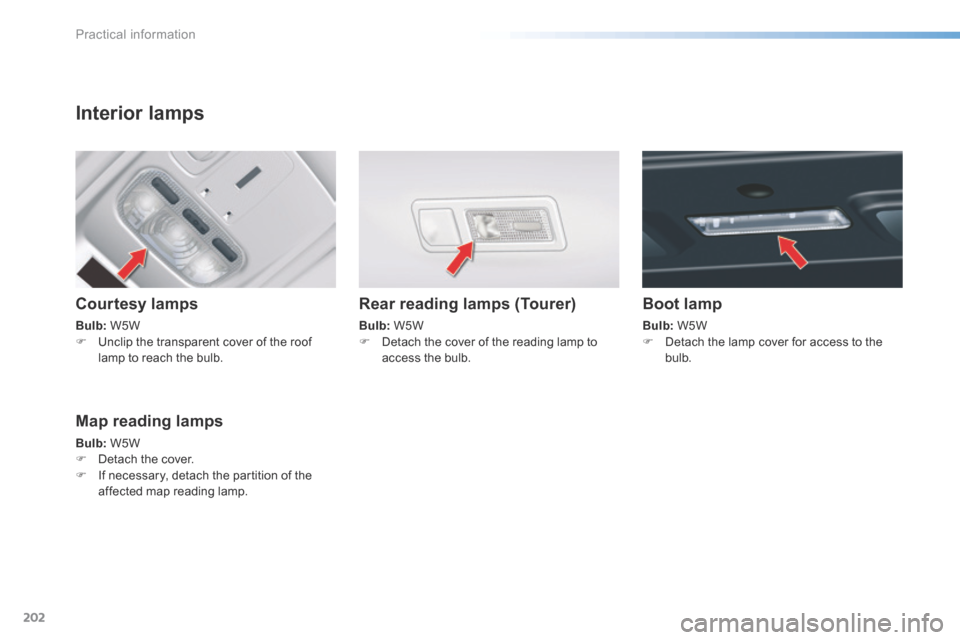
Interior lamps
Courtesy lamps
Bulb: W5W
F Unclip the transparent cover of the roof
lamp to reach the bulb.
Rear reading lamps (Tourer)
Bulb: W5W
F Detach the cover of the reading lamp to
access the bulb.
Map reading lamps
Bulb: W5W
F Detach the cover.
F If necessary, detach the partition of the
affected map reading lamp.
Boot lamp
Bulb: W5W
F Detach the lamp cover for access to the
bulb.
Practical information