air suspension Citroen C5 DAG 2007.5 (DC/DE) / 1.G Owner's Manual
[x] Cancel search | Manufacturer: CITROEN, Model Year: 2007.5, Model line: C5 DAG, Model: Citroen C5 DAG 2007.5 (DC/DE) / 1.GPages: 231, PDF Size: 8.02 MB
Page 6 of 231

II
99
24
33
38
39
3736
35
22
23
30
28
25
27
26
29
31
3234
41
40
IN BRIEF
D A S H B O A R D
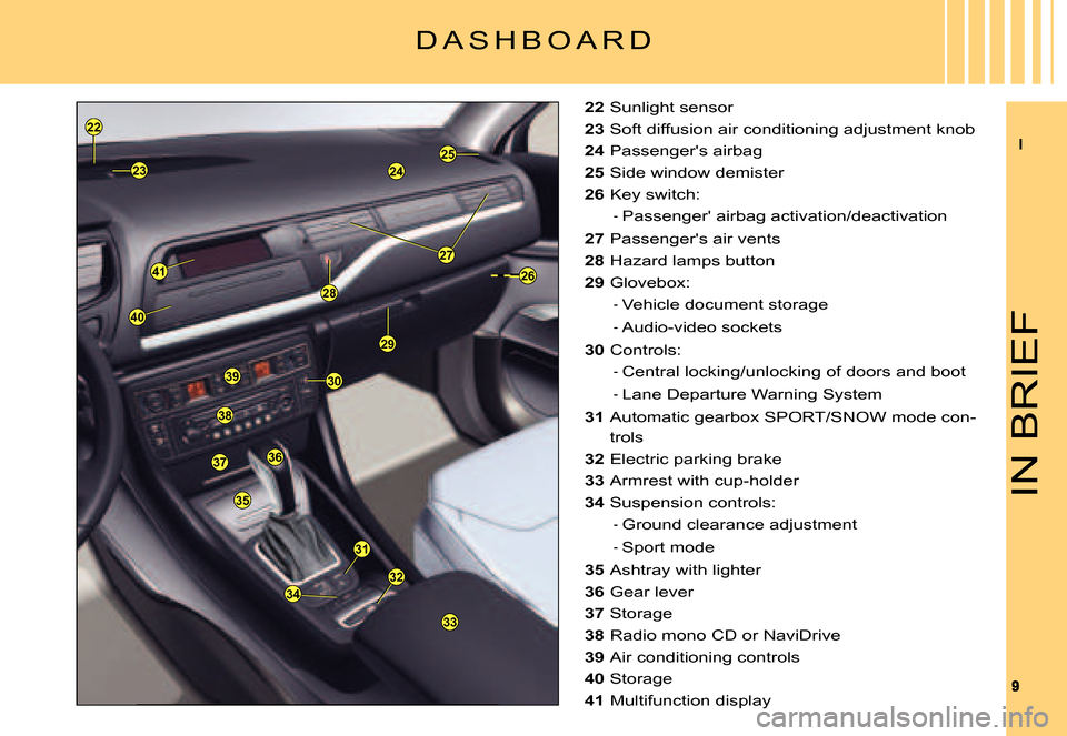
22 Sunlight sensor
23 Soft diffusion air conditioning adjustment knob
24 Passenger's airbag
25 Side window demister
26 Key switch:
Passenger' airbag activation/deactivation
27 Passenger's air vents
28 Hazard lamps button
29 Glovebox:
Vehicle document storage
Audio-video sockets
30 Controls:
Central locking/unlocking of doors and boot
Lane Departure Warning System
31 Automatic gearbox SPORT/SNOW mode con-
trols
32 Electric parking brake
33 Armrest with cup-holder
34 Suspension controls:
Ground clearance adjustment
Sport mode
35 Ashtray with lighter
36 Gear lever
37 Storage
38 Radio mono CD or NaviDrive
39 Air conditioning controls
40 Storage
41 Multifunction display
-
-
-
-
-
-
-
Page 151 of 231

155
V
T A B L E O F F U S E S
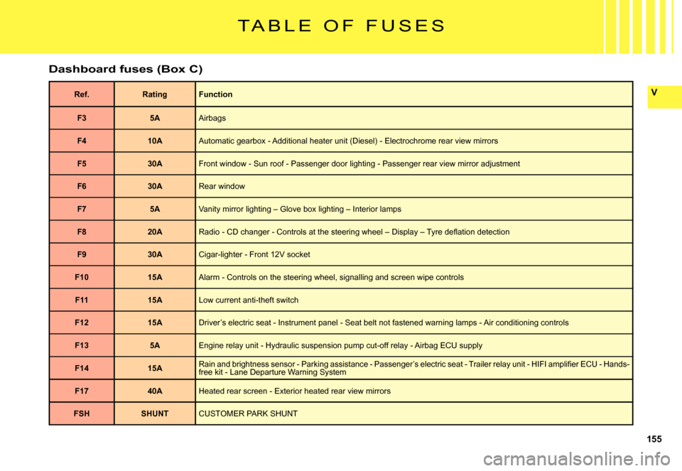
Dashboard fuses (Box C)
Ref.RatingFunction
F35AAirbags
F410AAutomatic gearbox - Additional heater unit (Diesel) - Electrochrome rear view mirrors
F530AFront window - Sun roof - Passenger door lighting - Passenger rear view mirror adjustment
F630ARear window
F75AVanity mirror lighting – Glove box lighting – Interior lamps
F820A�R�a�d�i�o� �-� �C�D� �c�h�a�n�g�e�r� �-� �C�o�n�t�r�o�l�s� �a�t� �t�h�e� �s�t�e�e�r�i�n�g� �w�h�e�e�l� �–� �D�i�s�p�l�a�y� �–� �T�y�r�e� �d�e�fl� �a�t�i�o�n� �d�e�t�e�c�t�i�o�n
F930ACigar-lighter - Front 12V socket
F1015AAlarm - Controls on the steering wheel, signalling and screen w ipe controls
F1115ALow current anti-theft switch
F1215ADriver’s electric seat - Instrument panel - Seat belt not fastened warning lamps - Air conditioning controls
F135AEngine relay unit - Hydraulic suspension pump cut-off relay - Airbag ECU supply
F1415A�R�a�i�n� �a�n�d� �b�r�i�g�h�t�n�e�s�s� �s�e�n�s�o�r� �-� �P�a�r�k�i�n�g� �a�s�s�i�s�t�a�n�c�e� �-� �P�a�s�s�e�n�g�e�r�’�s� �e�l�e�c�t�r�i�c� �s�e�a �t� �-� �T�r�a�i�l�e�r� �r�e�l�a�y� �u�n�i�t� �-� �H�I�F�I� �a�m�p�l�i�fi� �e�r� �E�C�U� �-� �H�a�n�d�s�-free kit - Lane Departure Warning System
F1740AHeated rear screen - Exterior heated rear view mirrors
FSHSHUNTCUSTOMER PARK SHUNT
Page 168 of 231

172
VI
3
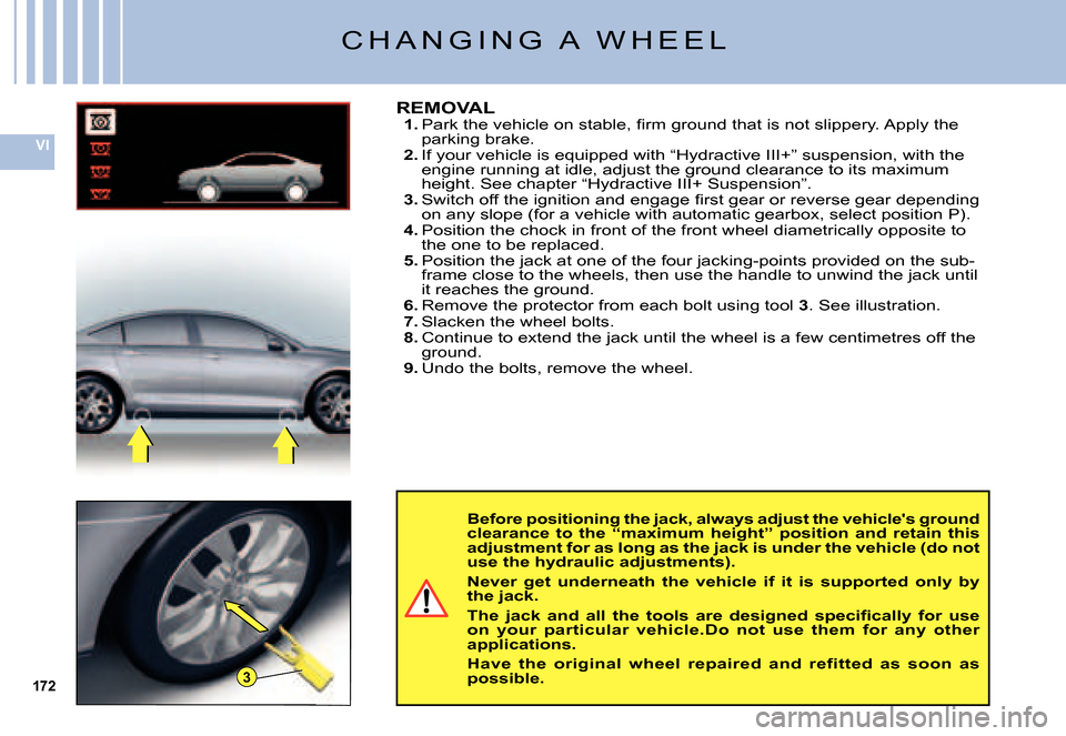
Before positioning the jack, always adjust the vehicle's ground clearance to the “maximum height” position and retain this adjustment for as long as the jack is under the veh icle (do not use the hydraulic adjustments).
Never get underneath the vehicle if it is supported only by the jack.
�T�h�e� �j�a�c�k� �a�n�d� �a�l�l� �t�h�e� �t�o�o�l�s� �a�r�e� �d�e�s�i�g�n�e�d� �s�p�e�c�i�fi� �c�a�l�l�y� �f�o�r� �u�s�e� on your particular vehicle.Do not use them for any other applications.
Have the original wheel repaired and refitted as soon as possible.
REMOVAL1. �P�a�r�k� �t�h�e� �v�e�h�i�c�l�e� �o�n� �s�t�a�b�l�e�,� �fi� �r�m� �g�r�o�u�n�d� �t�h�a�t� �i�s� �n�o�t� �s�l�i�p�p�e�r�y�.� �A�p �p�l�y� �t�h�e� parking brake.2. If your vehicle is equipped with “Hydractive III+” suspension, wit h the engine running at idle, adjust the ground clearance to its maximum height. See chapter “Hydractive III+ Suspension”.3. �S�w�i�t�c�h� �o�f�f� �t�h�e� �i�g�n�i�t�i�o�n� �a�n�d� �e�n�g�a�g�e� �fi� �r�s�t� �g�e�a�r� �o�r� �r�e�v�e�r�s�e� �g�e�a�r� �d�e�p�e�n�d�i�n�g� on any slope (for a vehicle with automatic gearbox, select posit ion P).4. Position the chock in front of the front wheel diametrically opposite to the one to be replaced.5. Position the jack at one of the four jacking-points provided o n the sub-frame close to the wheels, then use the handle to unwind the jack until it reaches the ground.6. Remove the protector from each bolt using tool 3. See illustration.7. Slacken the wheel bolts.8. Continue to extend the jack until the wheel is a few centimetres off the ground.9. Undo the bolts, remove the wheel.
C H A N G I N G A W H E E L