engine Citroen C5 RHD 2015 (RD/TD) / 2.G Repair Manual
[x] Cancel search | Manufacturer: CITROEN, Model Year: 2015, Model line: C5 RHD, Model: Citroen C5 RHD 2015 (RD/TD) / 2.GPages: 344, PDF Size: 12.96 MB
Page 185 of 344

183
Fuel tank
Capacity of the tank: approximately 71 litres*.
Low fuel level
When the minimum level
in the tank is reached, this
warning lamp comes on in the
instrument panel, accompanied
by an audible warning and a message in the
multifunction screen. When it first comes on,
there remains around 5 litres of fuel in the tank.
You must refuel to avoid running out of fuel.
F
P
ress at the top left corner, then pull on its
edge. F
t
urn the key a quarter turn to lock and
unlock the filler cap,
F
w
hen refuelling, place the cap on hook A,
F
f
ill the tank, but do not persist after the
third cut-off ; this could cause your vehicle
to malfunction.
While you are refuelling, the engine must be
stopped and the ignition switched off.
For a petrol engine with a catalytic
converter, unleaded fuel is compulsory.
Opening the fuel flap Refuelling
* 55 litres for Slovakia. Additions of fuel must be of at least
5 litres to be taken into account by the
fuel gauge.
The filler neck is narrower to ensure
that only unleaded petrol nozzles can
be put in.
Opening the filler cap may create a
noise of an inrush of air. This vacuum,
which is entirely normal, is caused by
the sealing of the fuel system.
With Stop & Start, never refuel with the
system in STOP mode; you must switch
off the ignition with the key.
8
Practical information
Page 186 of 344

184
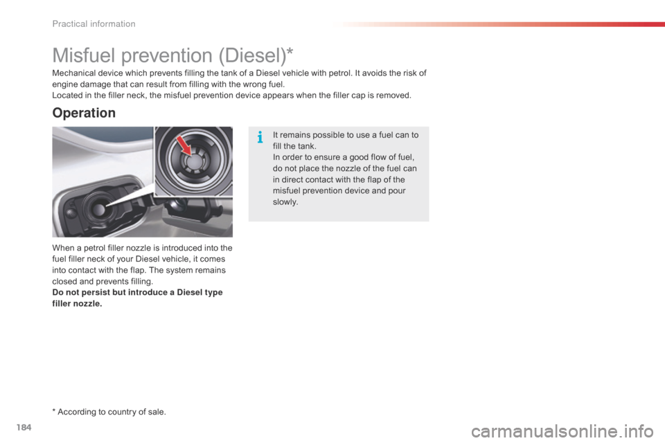
Misfuel prevention (Diesel)*
When a petrol filler nozzle is introduced into the
fuel filler neck of your Diesel vehicle, it comes
into contact with the flap. The system remains
closed and prevents filling.
Do not persist but introduce a Diesel type
filler nozzle.
* According to country of sale. Mechanical device which prevents filling the tank of a Diesel vehicle with petrol. It avoids the risk of
engine damage that can result from filling with the wrong fuel.
Located in the filler neck, the misfuel prevention device appears when the filler cap is removed.
Operation
It remains possible to use a fuel can to
fill the tank.
In order to ensure a good flow of fuel,
do not place the nozzle of the fuel can
in direct contact with the flap of the
misfuel prevention device and pour
s l ow l y.
Practical information
Page 187 of 344

185
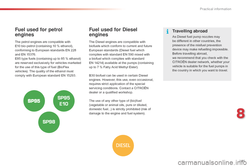
Fuel used for petrol
engines
The petrol engines are compatible with
E10 bio-petrol (containing 10 % ethanol),
conforming to European standards EN 228
and EN 15376.
E85 type fuels (containing up to 85 % ethanol)
are reserved exclusively for vehicles marketed
for the use of this type of fuel (BioFlex
vehicles). The quality of the ethanol must
comply with European standard EN 15293.
Fuel used for Diesel
engines
The Diesel engines are compatible with
biofuels which conform to current and future
European standards (Diesel fuel which
complies with standard EN 590 mixed with
a biofuel which complies with standard
EN
14214) available at the pumps (containing
up to 7 % Fatty Acid Methyl Ester).
B30 biofuel can be used in certain Diesel
engines. However, this use, even occasional,
requires strict application of the special
servicing conditions. Contact a CITROËN
dealer or a qualified workshop.
The use of any other type of (bio)fuel
(vegetable or animal oils, pure or diluted,
domestic fuel...) is strictly prohibited (risk of
damage to the engine and fuel system).
Travelling abroad
As Diesel fuel pump nozzles may
be different in other countries, the
presence of the misfuel prevention
device may make refuelling impossible.
Before travelling abroad,
we
recommend that you check with the
CITROËN dealer network, whether your
vehicle is suitable for the fuel pumps in
the country in which you want to travel.
8
Practical information
Page 188 of 344

186
Bleeding the Diesel fuel filter
Protective cover
Removing the cover
Bleeding water from the
fuel filter
Bleed regularly (at each oil change).
To bleed the water, slacken the bleed screw or
the water in diesel fuel sensor, located at the
base of the filter.
Continue until all the water has flowed out.
Then tighten the bleed screw or the water
detection sensor.
HDi 115 and HDi 160 engines
F
P
ull the protective cover upwards to
remove it.
HDi 140 engine
F
R
emove the protective cover by first
unclipping at 3 , then 1 and 4.
F
U
nclip at 2 by pulling towards you,
then lift up.Refitting
F Firstly clip in at 2 .
F L ower and centre the cover.
F
C
lip in at 3 and 4 , pushing vertically and
gently from the rear.
F
C
lip in at 1 pushing vertically.
Practical information
Page 189 of 344

187
Running out of fuel (Diesel)
F Unclip the protective cover to gain access to the priming pump.
F
U
nclip the protective cover to gain access
to the priming pump.
Priming the fuel system
In the event of running out of fuel:
F a fter filling (minimum 5 litres) and removing
the protective cover, operate the manual
priming pump, until some resistance is felt,
F
o
perate the starter motor while depressing
the accelerator pedal slightly until the
engine starts. HDi engines make use of advanced
technology.
For any work on your vehicle, contact
a qualified workshop that has the
skills and equipment required, which a
CITROËN dealer is able to provide.
If the engine fails to start at the first attempt,
wait fifteen seconds before trying again.
If the engine fails to start after a few attempts,
operate the priming pump again and then try to
start the engine.
When the engine is idling, accelerate slightly to
complete the bleeding of the circuit.
HDi 115 engine
HDi 140 and HDi 160 engines
8
Practical information
Page 191 of 344

189
Using the kit
F Switch off the ignition.
F A ffix the speed limitation sticker to the
vehicle's steering wheel to remind you that
a wheel is in temporary use. F
C heck that the switch A is in position "0"
.
F C onnect the pipe of the cartridge 1 to the
valve of the tyre to be repaired. F
C onnect the compressor's electric plug to
the vehicle's 12 V socket.
F
S
tart the vehicle and leave the engine
running.
8
Practical information
Page 193 of 344

191
F Connect the compressor's electric plug to the vehicle's 12 V socket again.
F
S
tart the vehicle again and leave the
engine running. F
A djust the pressure using the compressor
(to inflate: switch A in position "1";
to
deflate: switch A in position "0" and
press button B ), in accordance with the
vehicle's tyre pressure label (located on
the door aperture on the left-hand side),
then remember to check that the leak has
been plugged correctly (no further loss of
pressure after several miles [kilometres]).
F
R
emove the compressor, then store the
whole kit.
F
D
rive at reduced speed (50 mph
[80
km/h] max) limiting the distance
travelled to approximately 120 miles
(200
km).
F
V
isit a CITROËN dealer or a qualified
workshop as soon as possible to have the
tyre repaired or replaced by a technician. Take care as sealant cartridge contains
ethylene-glycol. This product is harmful
if swallowed and causes irritation to the
eyes. Keep it out of reach of children.
The expiry date of the sealant is
indicated on the base of the cartridge.
The cartridge is designed for a single
use; even if only partly used, it must be
replaced.
After use, do not discard the cartridge
into the environment, take it to a
CITROËN dealer or an authorised
waste disposal site.
Do not forget to obtain a new cartridge,
available from CITROËN dealers or a
qualified workshop.
If the vehicle is fitted with tyre under-
inflation detection, the tyre under-
inflation warning lamp will remain on
after the wheel has been repaired until
the system is reinitialised by a CITROËN
dealer or a qualified workshop.
8
Practical information
Page 196 of 344

194
Removing a wheel
F Park the vehicle on stable, firm ground that is not slippery. apply the parking brake.
F
I
f your vehicle is equipped with
"Hydractive
III+" suspension, with the
engine running at idle, adjust the ground
clearance to its maximum height.
F
S
witch off the ignition and engage first gear
(position R for an electronic gearbox; P for
an automatic gearbox).
F
I
f your vehicle is fitted with "Hydractive III+"
suspension, position the chock, whichever
direction the gradient may be in, in front of
the front wheel diametrically opposite to
the one to be replaced.
List of operations
F Remove the protector from each bolt using tool 3 .
F
F
it the security bolt socket to the
wheelbrace to slacken the security bolt
(depending on equipment).
F
S
lacken the other bolts using just the
wheelbrace 1 .
Before positioning the jack:
F
A
lways adjust the vehicle’s ground
clearance to the "maximum height"
position and retain this adjustment
for as long as the jack is under the
vehicle (do not use the hydraulic
adjustments),
F
E
nsure that any passengers have
left the vehicle and are in a safe
place.
Never get underneath the vehicle if it is
supported only by the jack.
The jack and all of the tools are specific
to your vehicle. Do not use them for any
other applications.
Have the original wheel repaired and
refitted as soon as possible.
Practical information
Page 215 of 344

213
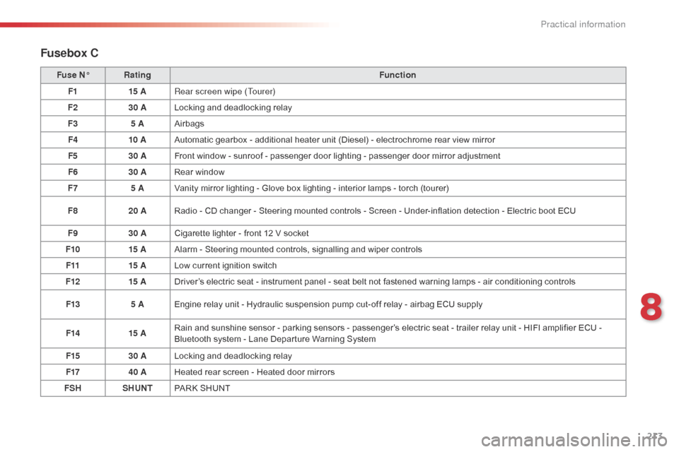
Fusebox C
Fuse N°Rating Function
F1 15 ARear screen wipe (Tourer)
F2 30 ALocking and deadlocking relay
F3 5 AAirbags
F4 10 AAutomatic gearbox - additional heater unit (Diesel) - electrochrome rear view mirror
F5 30 AFront window - sunroof - passenger door lighting - passenger door mirror adjustment
F6 30 ARear window
F7 5 AVanity mirror lighting - Glove box lighting - interior lamps - torch (tourer)
F8 20 ARadio - CD changer - Steering mounted controls - Screen - Under-inflation detection - Electric boot ECU
F9 30 ACigarette lighter - front 12 V socket
F10 15 AAlarm - Steering mounted controls, signalling and wiper controls
F11 15 ALow current ignition switch
F12 15 ADriver’s electric seat - instrument panel - seat belt not fastened warning lamps - air conditioning controls
F13 5 AEngine relay unit - Hydraulic suspension pump cut-off relay - airbag ECU supply
F14 15 ARain and sunshine sensor - parking sensors - passenger’s electric seat - trailer relay unit - HIFI amplifier ECU -
Bluetooth system - Lane Departure Warning System
F15 30 ALocking and deadlocking relay
F17 40 AHeated rear screen - Heated door mirrors
FSH SHUNTPARK SHUNT
8
Practical information
Page 216 of 344

214
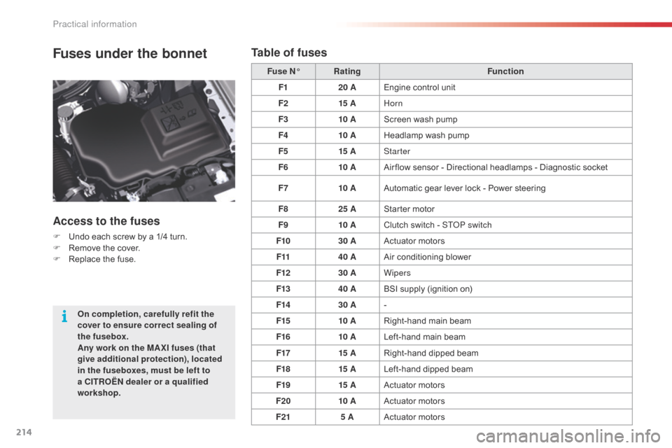
Fuses under the bonnet
Access to the fuses
F Undo each screw by a 1/4 turn.
F R emove the cover.
F
R
eplace the fuse. Fuse N°
Rating Function
F1 20 AEngine control unit
F2 15 AHorn
F3 10 AScreen wash pump
F4 10 AHeadlamp wash pump
F5 15 AStarter
F6 10 AAir flow sensor - Directional headlamps - Diagnostic socket
F7 10 AAutomatic gear lever lock - Power steering
F8 25 AStarter motor
F9 10 AClutch switch - S
T
o
P s
witch
F10 30 AActuator motors
F11 40 AAir conditioning blower
F12 30 AWipers
F13 40 ABSI supply (ignition on)
F14 30 A-
F15 10 ARight-hand main beam
F16 10 ALeft-hand main beam
F17 15 ARight-hand dipped beam
F18 15 ALeft-hand dipped beam
F19 15 AActuator motors
F20 10 AActuator motors
F21 5 AActuator motors
On completion, carefully refit the
cover to ensure correct sealing of
the fusebox.
Any work on the MA XI fuses (that
give additional protection), located
in the fuseboxes, must be left to
a CITROËN dealer or a qualified
workshop.
Table of fuses
Practical information