ABS CITROEN C6 2005 Owners Manual
[x] Cancel search | Manufacturer: CITROEN, Model Year: 2005, Model line: C6, Model: CITROEN C6 2005Pages: 223, PDF Size: 4.26 MB
Page 37 of 223

Downloaded from www.Manualslib.com manuals search engine 31
ENGINE
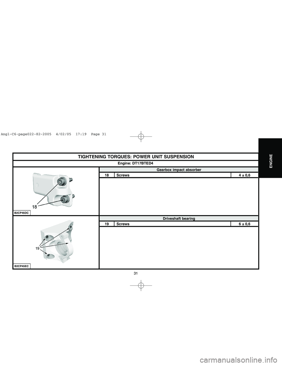
TIGHTENING TORQUES: POWER UNIT SUSPENSION
Gearbox impact absorber
18 Screws 4 ± 0,6
Driveshaft bearing
19 Screws 6 ± 0,6Engine: DT17BTED4
B2CP45ECB2CP45DC
Angl-C6-page022-82-2005 4/02/05 17:19 Page 31
Page 115 of 223

Downloaded from www.Manualslib.com manuals search engine 109
CLUTCH
GEARBOX
TRANSMISSION
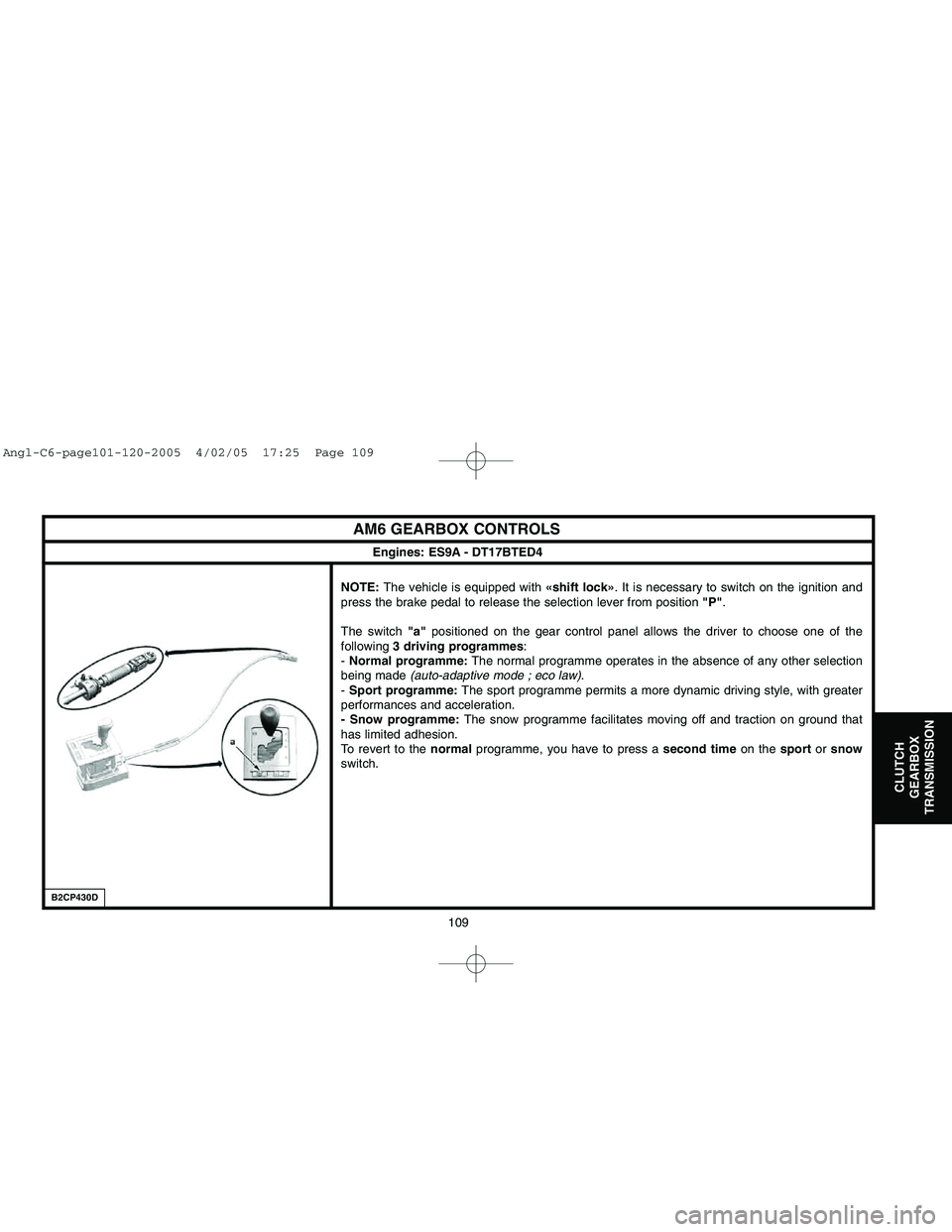
AM6 GEARBOX CONTROLSNOTE:The vehicle is equipped with «shift lock». It is necessary to switch on the ignition and
press the brake pedal to release the selection lever from position "P".
The switch "a"positioned on the gear control panel allows the driver to choose one of the
following 3 driving programmes:
- Normal programme:The normal programme operates in the absence of any other selection
being made (auto-adaptive mode ; eco law).
- Sport programme:The sport programme permits a more dynamic driving style, with greater
performances and acceleration.
- Snow programme:The snow programme facilitates moving off and traction on ground that
has limited adhesion.
To revert to the normalprogramme, you have to press a second timeon the sportor snow
switch.
B2CP430D
Engines: ES9A - DT17BTED4
Angl-C6-page101-120-2005 4/02/05 17:25 Page 109
Page 144 of 223

Downloaded from www.Manualslib.com manuals search engine 138
AXLES
SUSPENSION
STEERING
FRONT AXLE: TIGHTENING TORQUES
Engines: ES9A - DT17BTED4
Front subframe
13 Front subframe frame tie-bar on Body 5 ± 0,714 Front subframe frame tie-bar on Front subframe frame 6,5 ± 0,915 Front absorber support tie-bar 6,5 ± 0,916 Front subframe frame on Subframe extension 10 ± 117 Front subframe frame crossmember 10 ± 118 Subframe extension on Front subframe 5,5 ± 0,519 Front subframe stabiliser bar 12,5 ± 1,220 Front subframe on Body 14 ± 1,421 Suspension lower arm on Front subframe 6,5 ± 0,622 Suspension lower arm on Front subframe 11 ± 1,123 Front anti-roll bar bearing on Front subframe 4,5 ± 0,624 Body yoke 10 ± 1
B3CP09HDB3CP09GD
Angl-C6-page121-169-2005 4/02/05 17:31 Page 138
Page 146 of 223

Downloaded from www.Manualslib.com manuals search engine 140
AXLES
SUSPENSION
STEERING
(1)Rear axle crossmember
(2)Rear axle crossmember rear rubber bush
(3)Rear axle crossmember front rubber bush
(4)Suspension longitudinal arm
NOTE:Rear axle in cast aluminium alloy, of multi-arm type.
(5)Suspension upper arm
(6)Rear pivot
(7)Hub-bearing
(8)Tracking adjustment rod
(9)Suspension lower arm
Hub-bearing:
- The rear hub-bearing is equipped with an ABS radial target (48pairs of poles).
Stub axle:
- Diameter 32 mm.
- The stub axle, joined onto the rear pivot, is not separable.
IMPERATIVE: The rear hub-bearing must not be placed in proximity to a source of
magnetism or of pollution by metal particles. Components must be clean and free from
any signs of abnormal wear or damage.
B3DP0BYDB3DP0BZD
REAR AXLE
Rear axleRear pivot
Angl-C6-page121-169-2005 4/02/05 17:31 Page 140
Page 177 of 223

Downloaded from www.Manualslib.com manuals search engine 171
BRAKES
B3FP7GED
BRAKING SYSTEM: GENERAL SPECIFICATIONS
Braking system
Braking circuit in the form of anX.
Disc brakes at the front and at the rear
(vehicles all types):
- The front brake discs are ventilated.
- The rear brake discs are ventilated.
Electric parking brake (FSE)acting via cables on the
rear wheels.
The compensator and main brake limiter functions are
assured by the ABS REFsystems.
ESPis fitted as standard on the entire range.
NOTE: - REF (EBD) =Electronic Brakeforce
Distribution.
- ESP =Electronic Stability Programme.
Braking circuit
Angl-C6-PAGE170-194-2005 4/02/05 17:35 Page 171
Page 178 of 223

Downloaded from www.Manualslib.com manuals search engine 172
BRAKES
B3FP7GFC
BRAKING SYSTEM: GENERAL SPECIFICATIONSComponents Supplier Reference Observations
Hydraulic valve blockLocated on the front LH chassis member:
TRWESP 4regulation channels
ECUVSC 440
25-way connector
Integral to the hydraulic valve block
2-way blackconnector
Front wheel sensor The sensors, of inductive type, are fitted on the pivot
SIEMENSAir gap non-adjustable: 0.25 to 1.65 mm
VDO 2-way blackconnector
Rear wheel sensor The sensors, of inductive type, are fitted on the pivot
Air gap non-adjustable: 0.23 to 1.35 mm
Front pivot bearingThe hub has a bearing with integral magnetic wheel
NSK(48 pairs of poles)
Rear hub bearingThe rear hub-bearing has a radial ABS target
(48 pairsof poles)
ABS/ESP hydraulic valve block
Angl-C6-PAGE170-194-2005 4/02/05 17:35 Page 172
Page 198 of 223

Downloaded from www.Manualslib.com manuals search engine 192
BRAKES
DRAINING, FILLING AND BLEEDING THE BRAKING SYSTEM
Filling the braking circuit.
WARNING: Use only the approved and recommended hydraulic fluids.
IMPERATIVE: Only use new brake fluid that has not emulsified; avoid any introduction of
impurities into the hydraulic circuit.
Fill the brake fluid reservoir (4).
Bleeding the primary braking circuit.
WARNING: During the bleed operations: take care to maintain the level of the brake fluid in
the reservoir, keep it topped up.
WARNING: The ABS system must not be in action during the bleed operation.
WARNING: Respect the sequence for the opening of the bleed screws.
Frontbrake caliper : Bleed screw (5).
Rearbrake caliper : Bleed screw (6).
Bleed each brake caliper, proceeding in the following sequence:
- Front LH wheel.
- Front RH wheel.
- Rear LH wheel.
- Rear RH wheel.
B3FP7H4DB3FP7H5D
Angl-C6-PAGE170-194-2005 4/02/05 17:35 Page 192