fuel pressure CITROEN C6 2005 Owners Manual
[x] Cancel search | Manufacturer: CITROEN, Model Year: 2005, Model line: C6, Model: CITROEN C6 2005Pages: 223, PDF Size: 4.26 MB
Page 5 of 223
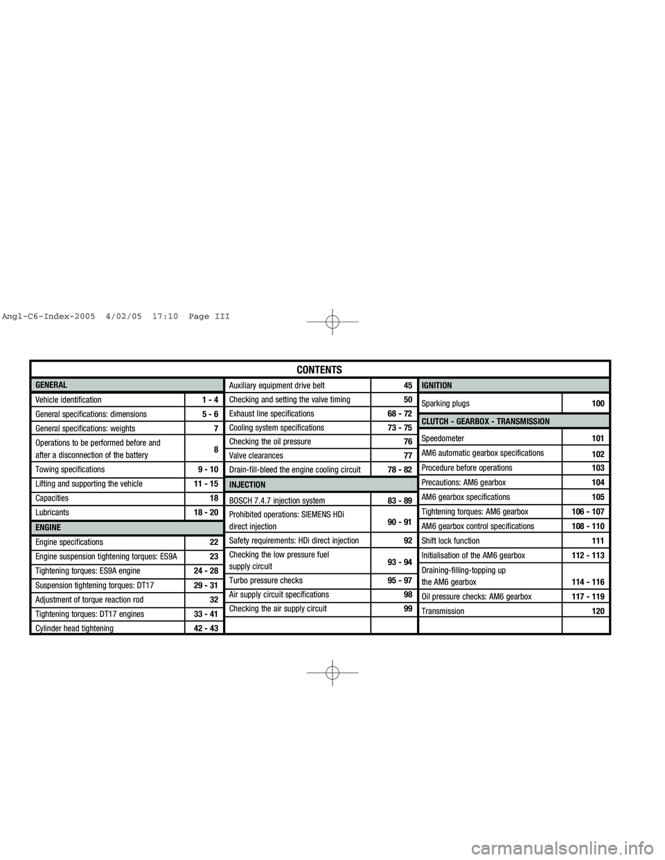
Downloaded from www.Manualslib.com manuals search engine GENERAL
Vehicle identification1 - 4
General specifications: dimensions 5 - 6
General specifications: weights7
Operations to be performed before and
after a disconnection of the battery8
Towing specifications9 - 10
Lifting and supporting the vehicle11 - 15
Capacities18
Lubricants18 - 20
ENGINE
Engine specifications22
Engine suspension tightening torques: ES9A23
Tightening torques: ES9A engine24 - 28
Suspension tightening torques: DT1729 - 31
Adjustment of torque reaction rod32
Tightening torques: DT17 engines33 - 41
Cylinder head tightening42 - 43IGNITION
Sparking plugs100
CLUTCH - GEARBOX - TRANSMISSION
Speedometer101
AM6 automatic gearbox specifications
102
Procedure before operations103
Precautions: AM6 gearbox104
AM6 gearbox specifications105
Tightening torques: AM6 gearbox106 - 107
AM6 gearbox control specifications 108 - 110
Shift lock function111
Initialisation of the AM6 gearbox112 - 113
Draining-filling-topping up
the AM6 gearbox114 - 116
Oil pressure checks: AM6 gearbox117 - 119
Transmission120
CONTENTS
Auxiliary equipment drive belt45
Checking and setting the valve timing50
Exhaust line specifications68 - 72
Cooling system specifications73 - 75
Checking the oil pressure76
Valve clearances77
Drain-fill-bleed the engine cooling circuit78 - 82
INJECTION
BOSCH 7.4.7 injection system83 - 89
Prohibited operations: SIEMENS HDi
direct injection90 - 91
Safety requirements: HDi direct injection92
Checking the low pressure fuel
supply circuit 93 - 94
Turbo pressure checks95 - 97
Air supply circuit specifications98
Checking the air supply circuit99
Angl-C6-Index-2005 4/02/05 17:10 Page III
Page 44 of 223
Downloaded from www.Manualslib.com manuals search engine 38
ENGINE
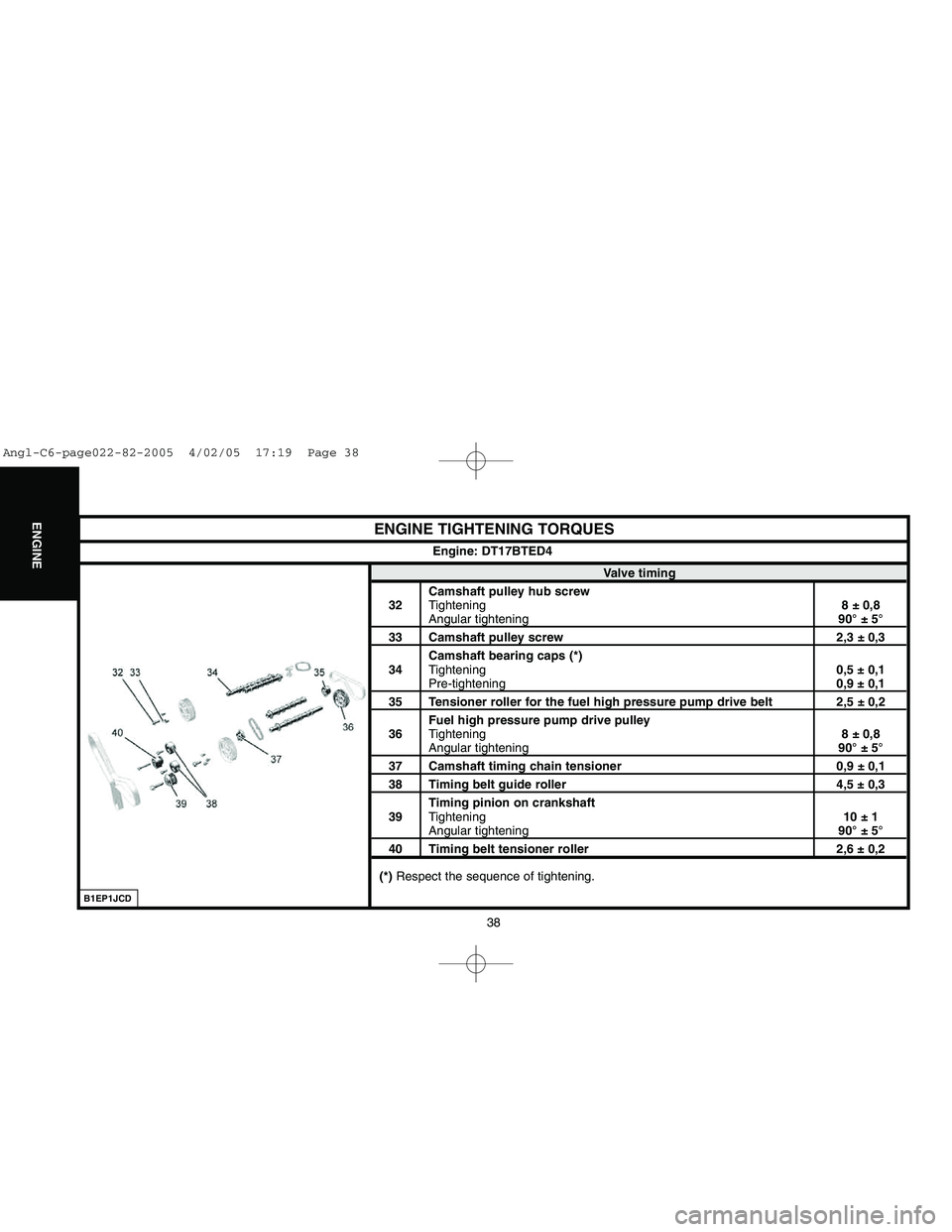
ENGINE TIGHTENING TORQUES
Valve timing
Camshaft pulley hub screw
32Tightening8 ± 0,8
Angular tightening90° ± 5°
33 Camshaft pulley screw 2,3 ± 0,3
Camshaft bearing caps (*)
34Tightening0,5 ± 0,1
Pre-tightening0,9 ± 0,1
35 Tensioner roller for the fuel high pressure pump drive belt 2,5 ± 0,2
Fuel high pressure pump drive pulley
36Tightening8 ± 0,8
Angular tightening90° ± 5°
37 Camshaft timing chain tensioner 0,9 ± 0,138 Timing belt guide roller 4,5 ± 0,3
Timing pinion on crankshaft
39Tightening10 ± 1
Angular tightening90° ± 5°
40 Timing belt tensioner roller 2,6 ± 0,2
(*) Respect the sequence of tightening.Engine: DT17BTED4
B1EP1JCD
Angl-C6-page022-82-2005 4/02/05 17:19 Page 38
Page 46 of 223
Downloaded from www.Manualslib.com manuals search engine 40
ENGINE
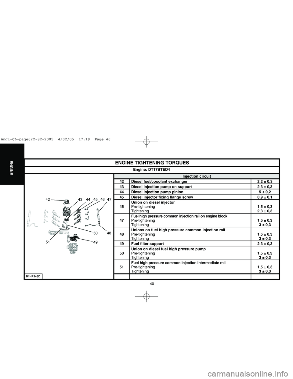
ENGINE TIGHTENING TORQUES
Injection circuit
42 Diesel fuel/cooolant exchanger 2,2 ± 0,343 Diesel injection pump on support 2,3 ± 0,344 Diesel injection pump pinion 5 ± 0,245 Diesel injector fixing flange screw 0,9 ± 0,1
Union on diesel injector
46Pre-tightening1,5 ± 0,3
Tightening2,3 ± 0,3
Fuel high pressure common injection rail on engine block
47Pre-tightening1,5 ± 0,3Tightening3 ± 0,3
Unions on fuel high pressure common injection rail
48Pre-tightening1,5 ± 0,3Tightening3 ± 0,3
49 Fuel filter support 2,3 ± 0,3
Union on diesel fuel high pressure pump
50Pre-tightening1,5 ± 0,3
Tightening3 ± 0,3
Fuel high pressure common injection intermediate rail
51Pre-tightening1,5 ± 0,3Tightening3 ± 0,3 Engine: DT17BTED4
B1HP246D
Angl-C6-page022-82-2005 4/02/05 17:19 Page 40
Page 57 of 223
![CITROEN C6 2005 Owners Manual Downloaded from www.Manualslib.com manuals search engine 51
ENGINE
51
CHECKING THE VALVE TIMING
Engine: ES9A
Tools.
[1]Camshaft setting pegs: (-).0187.B
[2]Crankshaft setting peg: (-).0187.A
[3]Fuel p CITROEN C6 2005 Owners Manual Downloaded from www.Manualslib.com manuals search engine 51
ENGINE
51
CHECKING THE VALVE TIMING
Engine: ES9A
Tools.
[1]Camshaft setting pegs: (-).0187.B
[2]Crankshaft setting peg: (-).0187.A
[3]Fuel p](/img/9/57744/w960_57744-56.png)
Downloaded from www.Manualslib.com manuals search engine 51
ENGINE
51
CHECKING THE VALVE TIMING
Engine: ES9A
Tools.
[1]Camshaft setting pegs: (-).0187.B
[2]Crankshaft setting peg: (-).0187.A
[3]Fuel pressure take-off union: 4192-T
[4]Belt retaining pin: (-).0187.J
[5]Exhaust camshaft hubs immobilising tool: (-).0187.F
[6]Inlet camshaft hubs immobilising tool: FACOM D12
[7]SEEM belt tension measuring equipment: 4122-T
Remove components as necessary for this operation.
Remove the auxiliaries drive belt (see corresponding operation).
Checking the valve timing.
Remove:
- The power steering pulley.
- The roller/dynamic tensioner assembly (11).
- The crankshaft pulley (12).
- The upper timing covers (9)and (10).
- The lower timing cover (13).
B1BP2BKC
Angl-C6-page022-82-2005 4/02/05 17:19 Page 51
Page 89 of 223
Downloaded from www.Manualslib.com manuals search engine 83
INJECTION
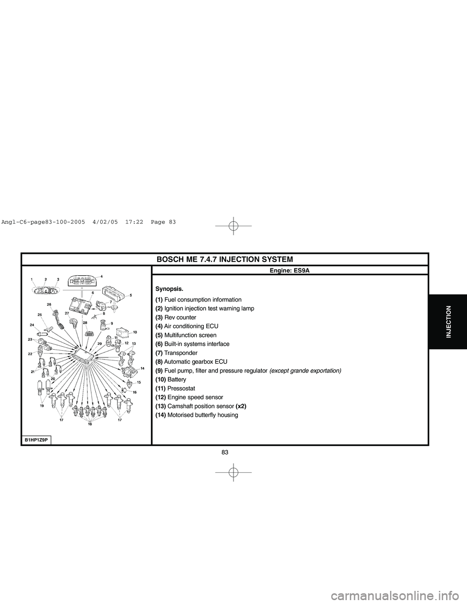
BOSCH ME 7.4.7 INJECTION SYSTEM
Engine: ES9A
Synopsis.
(1) Fuel consumption information
(2)Ignition injection test warning lamp
(3)Rev counter
(4)Air conditioning ECU
(5)Multifunction screen
(6)Built-in systems interface
(7)Transponder
(8)Automatic gearbox ECU
(9)Fuel pump, filter and pressure regulator (except grande exportation)
(10)Battery
(11)Pressostat
(12)Engine speed sensor
(13)Camshaft position sensor (x2)
(14)Motorised butterfly housing
B1HP1Z9P
Angl-C6-page83-100-2005 4/02/05 17:22 Page 83
Page 92 of 223
Downloaded from www.Manualslib.com manuals search engine 86
INJECTION
BOSCH ME 7.4.7 INJECTION SYSTEM
Engine: ES9AFuel circuit
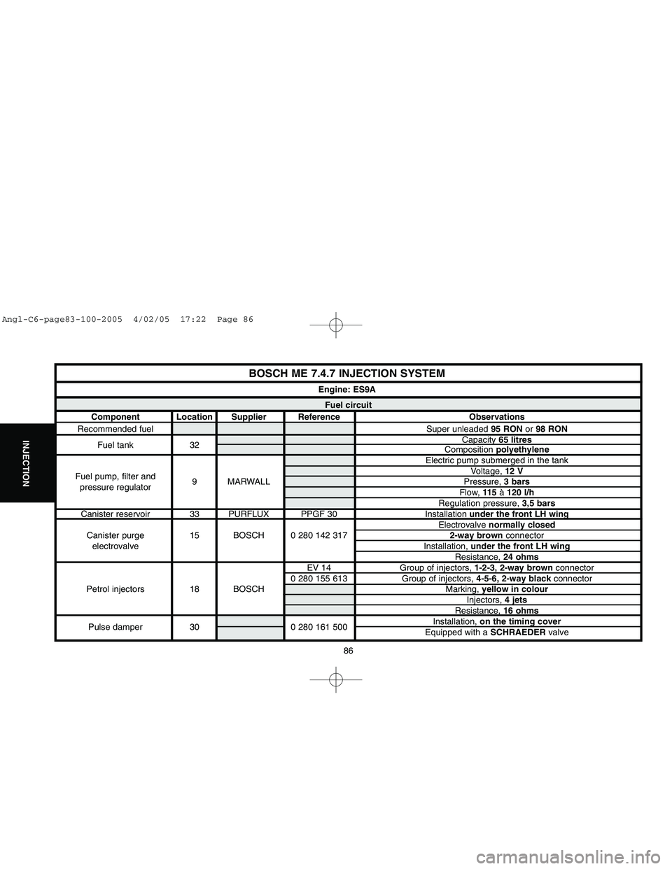
Component Location Supplier Reference Observations
Recommended fuel Super unleaded 95 RONor 98 RON
Fuel tank 32Capacity 65 litres
Composition polyethylene
Electric pump submerged in the tank
Fuel pump, filter andVoltage, 12 V
pressure regulator9 MARWALL Pressure, 3 bars
Flow, 115 à 120 l/h
Regulation pressure, 3,5 bars
Canister reservoir 33 PURFLUX PPGF 30 Installation under the front LH wing
Electrovalve normally closed
Canister purge 15 BOSCH 0 280 142 3172-way brownconnector
electrovalveInstallation, under the front LH wing
Resistance, 24 ohms
EV 14 Group of injectors, 1-2-3, 2-way brownconnector
0 280 155 613 Group of injectors, 4-5-6, 2-way blackconnector
Petrol injectors 18 BOSCH Marking, yellow in colour
Injectors, 4 jets
Resistance, 16 ohms
Pulse damper 30 0 280 161 500Installation, on the timing cover
Equipped with a SCHRAEDERvalve
Angl-C6-page83-100-2005 4/02/05 17:22 Page 86
Page 96 of 223

Downloaded from www.Manualslib.com manuals search engine 90
INJECTION
PROHIBITED OPERATIONS: SIEMENS HDI DIRECT INJECTION SYSTEM
Engine: DT17BTED4
Cleaning.
The use of high pressure cleaners is prohibited.
Do not use compressed air.
Fuel supply circuit.
Required fuel: Diesel.
WARNING: Do not use other fuels.
Electrical circuit.
Swapping injection ECUs between two vehicles will render it impossible to start either vehicle.
It is forbiddento supply a diesel injector with 12 volts.
Do not disconnect a diesel injector when the engine is running.
Fuel high pressure pump.
Do not separate the fuel high pressure pump (1)from the following components:
- The sealing ring (a)(no replacement parts).
- The high pressure outlet connector (b)(will cause a malfunction).
- The fuel pressure regulator (c)(no replacement parts).
- The flow electrovalve (d)(no replacement parts).
B1HP23GC
Angl-C6-page83-100-2005 4/02/05 17:22 Page 90
Page 97 of 223

Downloaded from www.Manualslib.com manuals search engine 91
INJECTION
PROHIBITED OPERATIONS: SIEMENS HDI DIRECT INJECTION SYSTEM
Engine: DT17BTED4
B1HP23JCB1HP23HC
Diesel injectors.
WARNING: Diesel and ultrasonic cleaners are prohibited.Do not separate the diesel injector carrier (2)from the following components:
- Diesel injector (g)(no replacement parts).
- The fuel flow actuator (e)(destruction).
Do not move the nut (f)(will cause a malfunction).
Do not separate the union (h)from a diesel injector.
It is forbidden
to clean the carbon deposits from the diesel injector nozzle.
Central fuel high pressure common injection rail.
Do not separate the fuel high pressure sensor (j)from the central fuel high pressure injection rail (3).
Angl-C6-page83-100-2005 4/02/05 17:22 Page 91
Page 98 of 223
Downloaded from www.Manualslib.com manuals search engine 92
INJECTION
SAFETY REQUIREMENTS: HDi DIRECT INJECTION SYSTEM
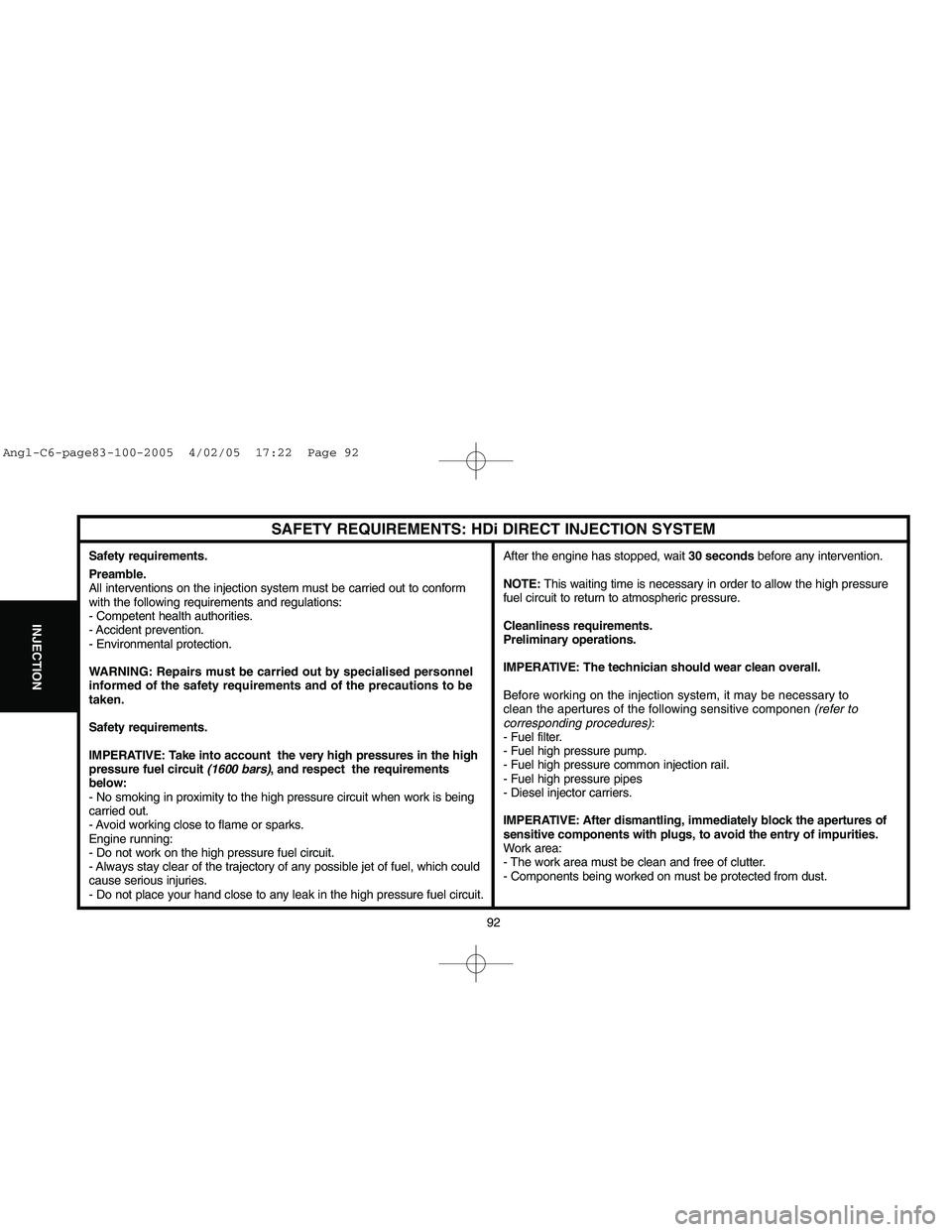
Safety requirements.
Preamble.
All interventions on the injection system must be carried out to conform
with the following requirements and regulations:
- Competent health authorities.
- Accident prevention.
- Environmental protection.
WARNING: Repairs must be carried out by specialised personnel
informed of the safety requirements and of the precautions to be
taken.
Safety requirements.
IMPERATIVE: Take into account the very high pressures in the high
pressure fuel circuit (1600 bars), and respect the requirements
below:
- No smoking in proximity to the high pressure circuit when work is being
carried out.
- Avoid working close to flame or sparks.
Engine running:
- Do not work on the high pressure fuel circuit.
- Always stay clear of the trajectory of any possible jet of fuel, which could
cause serious injuries.
- Do not place your hand close to any leak in the high pressure fuel circuit.After the engine has stopped, wait 30 secondsbefore any intervention.
NOTE:This waiting time is necessary in order to allow the high pressure
fuel circuit to return to atmospheric pressure.
Cleanliness requirements.
Preliminary operations.
IMPERATIVE: The technician should wear clean overall.
Before working on the injection system, it may be necessary to
clean the apertures of the following sensitive componen (refer to
corresponding procedures):
- Fuel filter.
- Fuel high pressure pump.
- Fuel high pressure common injection rail.
- Fuel high pressure pipes
- Diesel injector carriers.
IMPERATIVE: After dismantling, immediately block the apertures of
sensitive components with plugs, to avoid the entry of impurities.
Work area:
- The work area must be clean and free of clutter.
- Components being worked on must be protected from dust.
Angl-C6-page83-100-2005 4/02/05 17:22 Page 92
Page 99 of 223
![CITROEN C6 2005 Owners Manual Downloaded from www.Manualslib.com manuals search engine 93
INJECTION
CHECKS: LOW PRESSURE FUEL SUPPLY CIRCUIT
Engine: DT17BTED4
Tools.
[1] Ø 10 mmlow pressure connector: 4215-T
[2] Ø 8 mmlow pressu CITROEN C6 2005 Owners Manual Downloaded from www.Manualslib.com manuals search engine 93
INJECTION
CHECKS: LOW PRESSURE FUEL SUPPLY CIRCUIT
Engine: DT17BTED4
Tools.
[1] Ø 10 mmlow pressure connector: 4215-T
[2] Ø 8 mmlow pressu](/img/9/57744/w960_57744-98.png)
Downloaded from www.Manualslib.com manuals search engine 93
INJECTION
CHECKS: LOW PRESSURE FUEL SUPPLY CIRCUIT
Engine: DT17BTED4
Tools.
[1] Ø 10 mmlow pressure connector: 4215-T
[2] Ø 8 mmlow pressure connector: 4218-T
[3]Pressure gauge for testing boost pressure: 4073-T Kit 4073-T
[4]Extension: 4251-T
Checks.
IMPERATIVE : Respect the safety and cleanliness requirements specific to high pressure
diesel injection (HDi) engines.
Connect the tool [1]between the booster pump and the fuel filter (white mark on the fuel supply
pipe).
Connect the tool [2]downstream of the diesel injectors, between the high pressure fuel pump and
the fuel filter green mark on the fuel return pipe.
Connect the tool [3]on tool [1]or on tool [2].
WARNING: Any check of pressure downstream of the fuel filter is prohibited.
NOTE:To check the pressures while the vehicle is being driven, insert the extension [4] between
tool [3]and tools [1]or [2].
B1BP3CRD
Angl-C6-page83-100-2005 4/02/05 17:22 Page 93