tyre pressure CITROEN C6 2005 Owners Manual
[x] Cancel search | Manufacturer: CITROEN, Model Year: 2005, Model line: C6, Model: CITROEN C6 2005Pages: 223, PDF Size: 4.26 MB
Page 6 of 223

Downloaded from www.Manualslib.com manuals search engine AXLES - SUSPENSION - STEERING
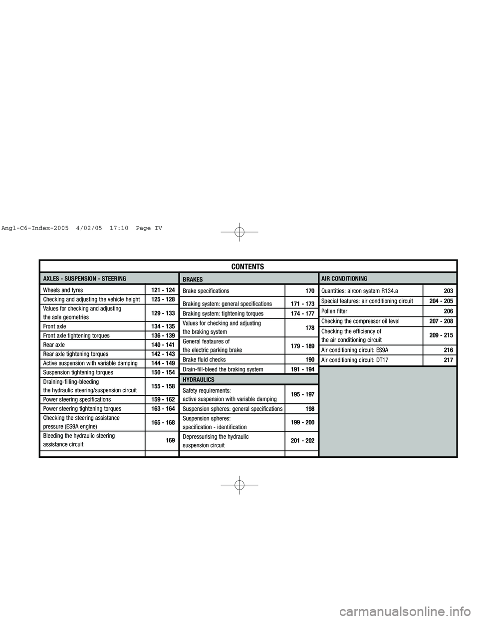
Wheels and tyres121 - 124
Checking and adjusting the vehicle height125 - 128
Values for checking and adjusting
the axle geometries129 - 133
Front axle134 - 135
Front axle tightening torques136 - 139
Rear axle140 - 141
Rear axle tightening torques142 - 143
Active suspension with variable damping144 - 149
Suspension tightening torques150 - 154
Draining-filling-bleeding
the hydraulic steering/suspension circuit155 - 158
Power steering specifications159 - 162
Power steering tightening torques163 - 164
Checking the steering assistance
pressure (ES9A engine)165 - 168
Bleeding the hydraulic steering
assistance circuit169AIR CONDITIONING
Quantities: aircon system R134.a 203
Special features: air conditioning circuit 204 - 205
Pollen filter206
Checking the compressor oil level207 - 208
Checking the efficiency of
the air conditioning circuit209 - 215
Air conditioning circuit: ES9A216
Air conditioning circuit: DT17217
CONTENTS
BRAKES
Brake specifications170
Braking system: general specifications171 - 173
Braking system: tightening torques174 - 177
Values for checking and adjusting
the braking system178
General feataures of
the electric parking brake179 - 189
Brake fluid checks190
Drain-fill-bleed the braking system191 - 194
HYDRAULICS
Safety requirements:
active suspension with variable damping195 - 197
Suspension spheres: general specifications 198
Suspension spheres:
specification - identification199 - 200
Depressurising the hydraulic
suspension circuit201 - 202
Angl-C6-Index-2005 4/02/05 17:10 Page IV
Page 7 of 223

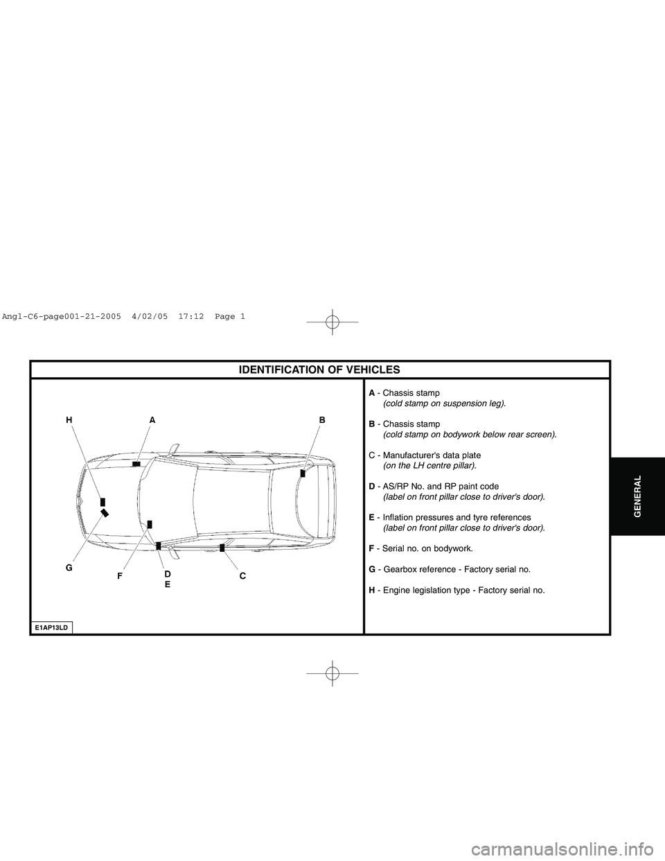
Downloaded from www.Manualslib.com manuals search engine IDENTIFICATION OF VEHICLES
E1AP13LD
A- Chassis stamp
(cold stamp on suspension leg).
B - Chassis stamp
(cold stamp on bodywork below rear screen).
C - Manufacturer's data plate
(on the LH centre pillar).
D - AS/RP No. and RP paint code
(label on front pillar close to driver's door).
E - Inflation pressures and tyre references
(label on front pillar close to driver's door).
F - Serial no. on bodywork.
G - Gearbox reference - Factory serial no.
H - Engine legislation type - Factory serial no.
GENERAL
Angl-C6-page001-21-2005 4/02/05 17:12 Page 1
Page 127 of 223

Downloaded from www.Manualslib.com manuals search engine 121
AXLES
SUSPENSION
STEERING
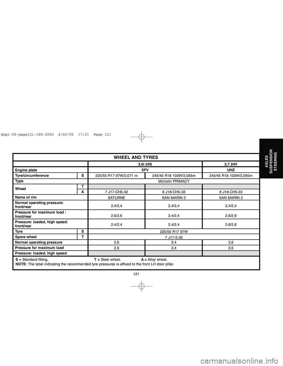
WHEEL AND TYRES
Engine plate
Tyre/circumference S
Type
WheelT
A
Name of rim
Normal operating pressure:
front/rear
Pressure for maximum load :
front/rear
Pressure: loaded, high speed:
front/rear
Tyre S
Spare wheel T
Normal operating pressure
Pressure for maximum load
Pressure: loaded, high speed 3.0i 24S 2,7 24V
XFV UHZ
225/55 R17 97W/2,071 m 245/45 R18 100W/2,065m 245/45 R18 100W/2,065m
Michelin PRIMACY
7 J17-CH5-32 8 J18-CH5-33 8 J18-CH5-33
SATURNE SAN MARIN 2 SAN MARIN 2
2,4/2,4 2,4/2,4 2,4/2,4
2,6/2,6 2,4/2,4 2,6/2,6
2,4/2,4 2,4/2,4 2,6/2,6
225/55 R17 97W
7 J17-5-32
2,6 2,4 2,6
2,6 2,4 2,6S =Standard fitting.T =Steel wheel.A=Alloy wheel.
NOTE:The label indicating the recommended tyre pressures is affixed to the front LH door pillar.
Angl-C6-page121-169-2005 4/02/05 17:31 Page 121
Page 128 of 223

Downloaded from www.Manualslib.com manuals search engine 122
AXLES
SUSPENSION
STEERING
WHEEL AND TYRESNOTE:The label indicating the recommended tyre pressures is affixed to the front
LH door pillar.
┬źa┬╗Recommended tyre inflation pressures (empty and under load)
┬źb┬╗Tyre specifications
┬źc┬╗Type of tyres
┬źd┬╗Recommended inflation pressure for the spare wheel
B2GP01FD
Identification of inflation pressures
Angl-C6-page121-169-2005 4/02/05 17:31 Page 122
Page 131 of 223
![CITROEN C6 2005 Owners Manual Downloaded from www.Manualslib.com manuals search engine AXLES
SUSPENSION
STEERING
125
CHECKING AND ADJUSTING VEHICLE HEIGHT
IMPERATIVE: Respect the safety and cleanliness requirements.
Tools.
[1]Gaug CITROEN C6 2005 Owners Manual Downloaded from www.Manualslib.com manuals search engine AXLES
SUSPENSION
STEERING
125
CHECKING AND ADJUSTING VEHICLE HEIGHT
IMPERATIVE: Respect the safety and cleanliness requirements.
Tools.
[1]Gaug](/img/9/57744/w960_57744-130.png)
Downloaded from www.Manualslib.com manuals search engine AXLES
SUSPENSION
STEERING
125
CHECKING AND ADJUSTING VEHICLE HEIGHT
IMPERATIVE: Respect the safety and cleanliness requirements.
Tools.
[1]Gauge for measuring radius of wheels (5 bolts): 9801-T
[2]Gauge for height under bodyshell: 2305-T
[3] LEXIAstation: 4171-T
[4] PROXIAstation: 4165-T
Preliminary operations.
Check the tyre pressures.
Place the vehicle on a 4 column lift.
Switch on the ignition.
Release the parking brake.
Put the vehicle in the high position.
Put the vehicle in the normal height position (driving height).
During:During the measuring, do not move the vehicle.
Reference heights: REFERENCE = Ignition switched on
Angl-C6-page121-169-2005 4/02/05 17:31 Page 125
Page 135 of 223

Downloaded from www.Manualslib.com manuals search engine AXLES
SUSPENSION
STEERING
129
A < B = Positive figure: + = TOE-IN
A > B = Negative figure: - = TOE-OUTNOTE
VALUES FOR CHECKING AND ADJUSTING AXLE GEOMETRIES
IMPERATIVE: Respect the safety and cleanliness requirements.
Tools.
[1]Gauge for measuring radius of wheels (5 bolts): 9801-T
[2]Gauge for height under bodyshell: 2305-T
WARNING: ┬źCheck and adjust the axle geometries at referenceheight┬╗.
Conditions for checking and adjusting.
Check the tyre pressures.
Place the vehicle on a 4 column lift.
Check and adjust if necessary the vehicle heights (see corresponding
operation).
Steering rack locked at its zero point (see corresponding operation).
Switch off the ignition before removing the tools from the wheels.
Lower the vehicle.
Start the engine.
Put the vehicle in the high position.
Put the vehicle in the normal height position (driving height).
Stop the engine.
Switch on the ignition.
Check and adjust the front and rear axle geometries at reference
height.
WARNING: Do not switch off the ignition during checking and
adusting of the front and rear axle geometries.
NOTE:Front of vehicle (following the arrow).
B3CP02UC
Angl-C6-page121-169-2005 4/02/05 17:31 Page 129