ignition Citroen CX 1974 1.G Workshop Manual
[x] Cancel search | Manufacturer: CITROEN, Model Year: 1974, Model line: CX, Model: Citroen CX 1974 1.GPages: 394
Page 4 of 394
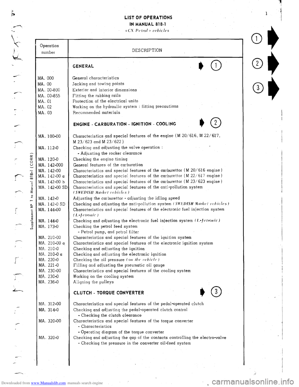
Downloaded from www.Manualslib.com manuals search engine Operation
number
VIA. 000
VIA. 00
VIA. 00-600
vlA. 00-655
VIA. 01
WA. 02
MA. 03
MA. 100-00
MA. 112-O
MA. 120-O
MA. 142-000
MA. 142-00
MA. 142-00 a
MA. 142-00 b
MA. 142-00 SI
MA. 142-O
MA. 142-O SD
MA. 144-00
MA. 144-O
MA. 173-O
MA. 210-00
MA. 210-00 a
MA. 210-O
MA. 210-O a
MA. 220-O
MA. 221-O
MA. 230-00
MA. 230-O
MA. 236-O
MA. 312-00
MA. 314-O
MA. 320-00
MA. 320-O LIST OF OPERATIONS
IN MANUAL 818-l
cc CX Petrol )) uehicles
DESCRIPTION GENERAL
General characteristics
Jacking and towing points
Exterior and interior dimensions
Fitting the rubbing rails
Protection of the electrical units
Working on the hydraulic system : fitting precautions
Recommended materials ENGINE - CA,RBURATlON - IGNITION - COOLING
+O 2
Characteristics and special features of the engine (M 20/616, M 22/ 617,
M 23/623 and M 23/622 )
Checking and adjusting the valve operation :
- Adjusting the rocker clearance
Checking the engine timing
General features of the carburation
Characteristics and special features of the carburettor (M 20/616 engine )
Characteristics and special features of the carburettor ( M 22/617 engine )
Characteristics and special features of the carburettor ( M 23/ 623 engine )
Characteristics and special features of the anti-pollution system
I SWEDISH Jlurket r,c~kicles )
Adjusting the carburettor - adjusting the idling speed
Checking and adjusting the anti-pollution system
(SIVI:‘DfSH Mdrkct rvhicles J
Characteristics and special features of the electronic fuel injection system
(L.~etKJnic )
Checking and adjusting the electronic fuel injection system (1..Jetrolzic)
Checking the petrol feed system
- Petrol pump, and petrol filter
Characteristics and special features of the ignition system
Characteristics and special features of the electronic ignition system
Checking and adjusting the ignition
Checkinq and adjusting the electronic ignition
Checking the oil pressure (on
the rvhicle )
Filling and adjusting the pneumatic oil gauge
Characteristics and special features of the cooling system
Working on the cooling system
Aligning the pulleys CLUTCH - TORQUE CONVERTER
*O 3
Characteristics and special features of the pedal-operated clutch
Checking and adjusting the pedal-operated clutch control
- Checking the clutch clearance
Characteristics and special features of the torque converter
- Characteristics
- Operating diagram of the torque converter
Checking and adjusting the gap of the contacts controlling the electro-valve
- Checking the pressure in the converter oil-feed system
Page 41 of 394
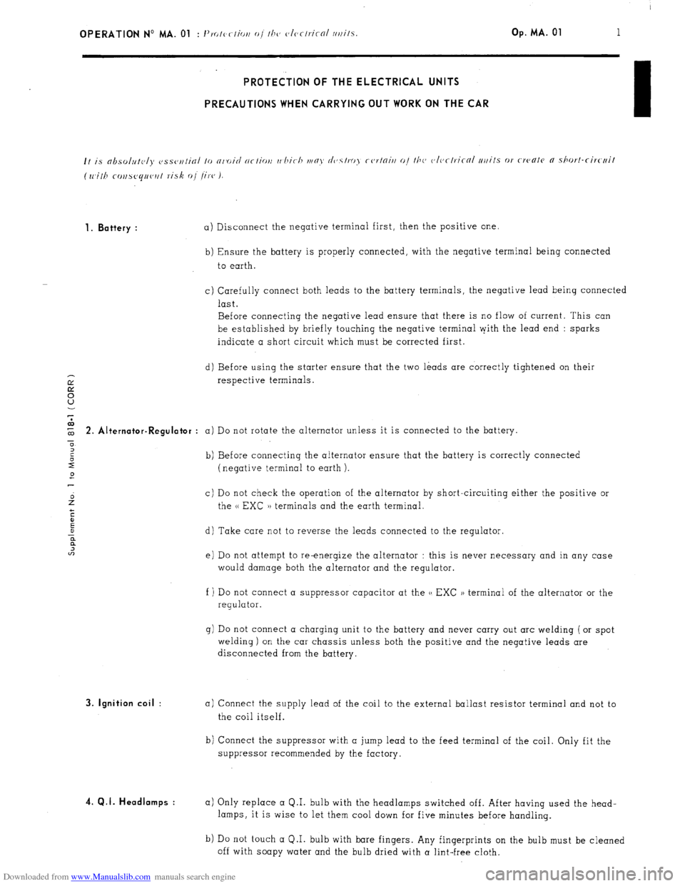
Downloaded from www.Manualslib.com manuals search engine OPERATION No MA. 01 : 1’. I, -1’ IO c ( lOi, o/ I/J<, c~lcrlricnl /l/lilS. Op. MA. 01 1 PROTECTION OF THE ELECTRICAL UNITS
PRECAUTIONS WHEN CARRYING OUT WORK ON THE CAR
1. Battery :
a) Disconnect the negative terminal first, then the positive one.
b) Ensure the battery is properly connected, with the negative terminal being connected
to earth.
c) Carefully connect both leads to the battery terminals, the negative lead being connected
last.
Before connecting the negative lead ensure that there is no flow of current. This can
be established by briefly touching the negative terminal pith the lead end : sparks
indicate a short circuit which must be corrected first.
d) Before using the starter ensure that the two leads are correctly tightened on their
respective terminals. $ 2. Alt ernator-Regulator :
a) Do not rotate the alternator unless it is connected to the battery.
0
2
2 b) Before connecting the alternator ensure that the battery is correctly connected
2 (negative terminal to earth ).
c) Do not check the operation of the alternator by short-circuiting either the positive or
the u EXC )) terminals and the earth terminal.
d) Take care not to reverse the leads connected to the regulator.
e) Do not attempt to re-energize the alternator : this is never necessary and in any case
would damage both the alternator and the regulator.
f ) Do not connect a suppressor capacitor at the u EXC )) terminal of the alternator or the
regulator.
g) Do not connect a charging unit to the battery and never carry out arc welding ( or spot
welding) on the car chassis unless both the positive and the negative leads are
disconnected from the battery. 3. Ignition coil :
4. Q.I. Headlamps :
a) Connect the supply lead of the coil to the external ballast resistor terminal and not to
the coil itself.
b) Connect the suppressor with a jump lead to the feed terminal of the coil. Only fit the
suppressor recommended by the factory.
a) Only replace a Q.I. bulb with the headlamps switched off. After having used the head-
lamps, it is wise to let them cool down for five minutes before handling.
b) Do not touch a Q.I. bulb with bare fingers. Any fingerprints on the bulb must be cleaned
off with soapy water and the bulb dried with a lint-free cloth.
Page 52 of 394
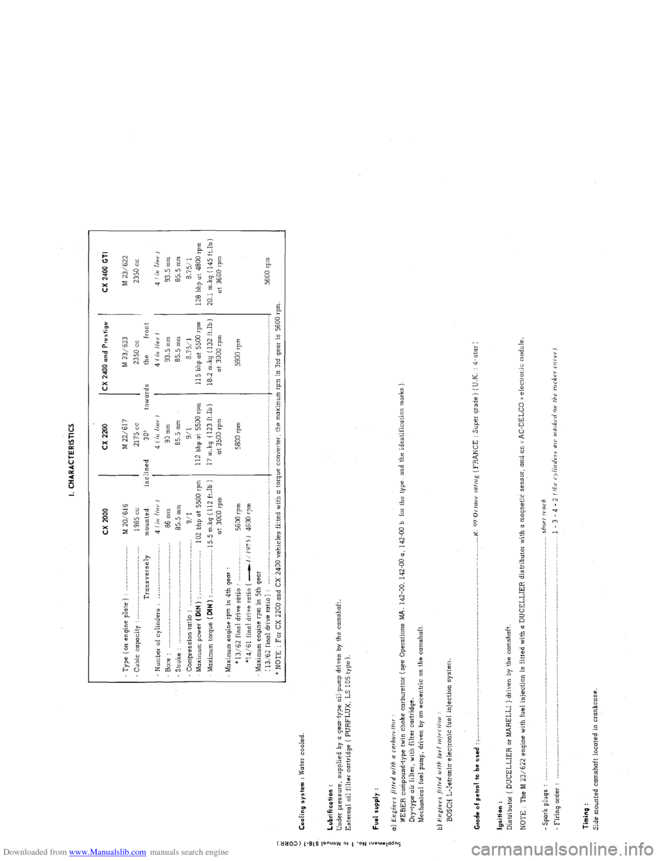
Downloaded from www.Manualslib.com manuals search engine I. CHARACTERISTICS
:
0
u
5 Cooling system : Water cooled.
z
T cx 2000 cx 2200 CX 2400 and Prestige
CX 2400 GTI
- Type ( on engine p’late ) : _..._................... M 20/616 M 22/617 M 23/ 623
M 23/622
Cubic capacity : . . .._......_...............
1985 cc 2175 cc 2350 cc 2350 cc
Transversely mounted, inclined
300 towards the front
Number of cylinders : _........................... 4 (iI/ linr, J 4 Iin linr,)
4 (irr /iUP J 4 f in lin i’ ,
Bore : 86 mm 90 mm 93.5 mm 93.5 mm
- Stroke : .,.,,_,.,.,....____.,.. .._._.....................
85.5 mm 85.5 mm 85.5 mm
85.5 mm
Compression ratio :
9/I 9/l 8.7511 8.7511
Maximum power ( DIN ) : . . . .._................... 102 bhp at 5500 rpm 112 bhp at 5500 rpm 115 bhp ot 5500 rpm
128 bhp at 4800 rpm
Maximum torque (DIN)
: . . 15.5 m.kg (112 ft.Ib ) 17 m.kq (123 ft.Ib) 18.2 m.kg ( 132 ft.Ib)
20.1 mkq (145 ft.Ib)
at 3000 rpm at 3500 rpm at 3000 rpm
at 3600 rpm
Maximum engine rpm in 4th gear :
* 13/62 final drive rtrtio :
5600 rpm 5800 rpm 5900 rpm
*14/61 final drive ratio ( -1 1’175 J 4600 rpm
Maximum engine rpm in 5th gear
(
13,‘62 final drive ratio ) : ,._............,..,........,....,.,........,..,.,..... .._.........,................ .._..._...................
5600 rpm
* NOTE : For CX 2200 and CX 2400 vehicles fitted with a torque converter, the maximum rpm in 3rd gear is 5600 rpm.
: Lubrification :
i
Under pressure, supplied by o gear-type oil-pump driven by the camshaft.
2
External oil filter cartridge ( PURFLUX, LS 105 type ).
d
z
;
i Fuel supply :
a
i a) Engines fitted u~ifh a rnrbuwffor
WEBER compound-type twin choke carburettor (s.ee Operations MA. 142-00, 142-00 a, 142-00 b far the type, and the identification marks )
Dry-type air filter, with filter cartridge.
Mechanical fuel pump, driven by on eccentric on the camshaft.
b) i?ugi,jes ji/f.rd II ith /LIP/ iniPr/ioo :
BOSCH L-Jetronic electronic fuel injection system
Grade of pet,ol to be used : > ._,,,,.,_.._,,,,,.,......... . .._...o....._............................................. K.
99 Orrani ralrrig (FRANCE : Super grade ) (U.K. : 4-star )
Ignition :
Distributor ( DUCELLIER or MARELLI ) driven by the camshaft.
NOTE : The M 23/622 engine with fuel injection is fitted with (I DUCELLIER distributor with a magnetic sensor, and an u AC-DELCO /a electronic module.
- Spark pluqs : .................................................................................................................................... shorf warh
Firing o&r : .................................................................................................................................... 1 - 3 - 4 - 2 f tbu cylinders ale INR&Cd 011 the roc6w COI rr,
Timing :
Side mounted camshaft located in crankcase.
Page 78 of 394
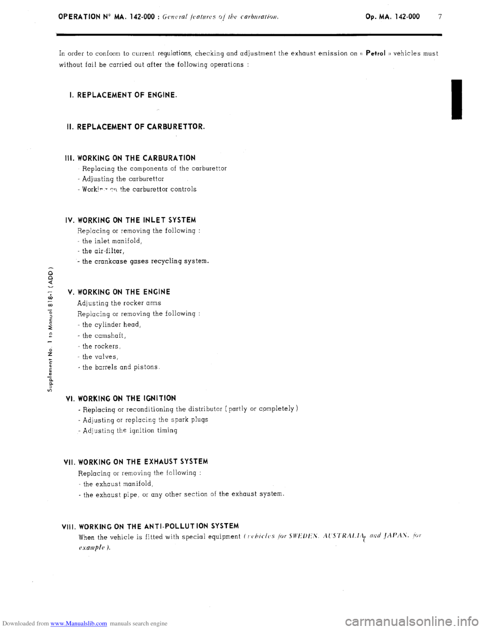
Downloaded from www.Manualslib.com manuals search engine OPERATION No MA. 142-000 : Gcnrrd 1.cnturcs 01. the cnrfxrr~tion. Op. MA. 142-000 7
In order to conform to current regulations, checking and adjustment the exhaust emission on u Petrol )) vehicles must
without fail be carried out after the following operations :
I. REPLACEMENT OF ENGINE.
II. REPLACEMENT OF CARBURETTOR.
Ill. WORKING ON THE CARBURATION
- Replacing the components of the carburettor
- Adjusting the carburettor
- Worki? - rri the carburettor controls
IV. WORKING ON THE INLET SYSTEM
Replacing or removing the following :
the inlet manifold,
- the air-filter,
- the crankcase gases recycling system.
V. WORKING ON THE ENGINE
Adjusting the rocker arms
Replacing or removing the following :
the cylinder head,
- the camshaft,
- the rockers,
- the valves,
_ the barrels and pistons.
VI. WORKING ON THE IGNITION
- Replacing or reconditioning the distributor ( partly or cpmpletely )
~ Adjusting or replacing the spark plugs
- Adjusting the ignition timing
VII. WORKING ON THE EXHAUST SYSTEM
Replacing or removing the following :
- the exhaust manifold,
- the exhaust pipe, or any other section of the exhaust system.
VIII. WORKING ON THE ANTI-POLLUTION SYSTEM
When the vehicle is fitted with special equipment C I c,hic-1~s /or SWIIllI:‘S. Al'S7'KAl.l~ll m;d JAI'A.\. /ot
Page 90 of 394
Downloaded from www.Manualslib.com manuals search engine OPERATION No MA. 142-O : Adj,,s/iaji f/a<, rarhnrt,//or Op. MA. 142.0
1
ADJUSTING THE IDLING SPEED
To carry out this adjustment, the following is needed
A tachometer
A device lor checkinq idling speed adjustments on the carburettor ( or on approved gas analyser )
- A CDA 23 checking oppmotus or a workshop test bench ( equipment mentioned in the Equipment and Repair
Materials list, or in the Tools and Equipment notes green notes )
NOTE : WEBER Carburettors ref. No W 54-50, 55-50, 69-50, 74-50 fitted on 1977 models onwards ore fitted with a
fool-proof plug ( white ) on the mixture screw. To adjust the exhaust emission, this plug has to be
removed, and
replaced, after adjustment, with a a Repair PI plug ( black ). See Op. MA, 142-000 for removing and fitting the plug,
and the necessary tools.
ADJUSTMENT CONDITIONS
1.
The idling speed adjus!ment must be carried out on an engine on which the rocker clearances and the ignition
are correctly set. with a clean air filter and
with the engine in good order.
2. Check that the butterflies return fully to their stops.
3. 30 not let pnythinq except the ignition and the engine cooling fan ( or ions ) impose any load on the alternator.
4. Run the engine to bring the
oil temperature up to 70 to 80’ C ( wait for the electric cooling fan ( or fans 1 to cut
in 1.
I. M 20/616, M 22/617, M 23/623 ENGINES I i< ?I< (5 wi/hr ,111 /or<,,,< co,1, <,r,cr or air ro,,di/io,ii?,g I ,I ‘-/
1. Wait for the electric cooling fan ( or fans ) to cut in.
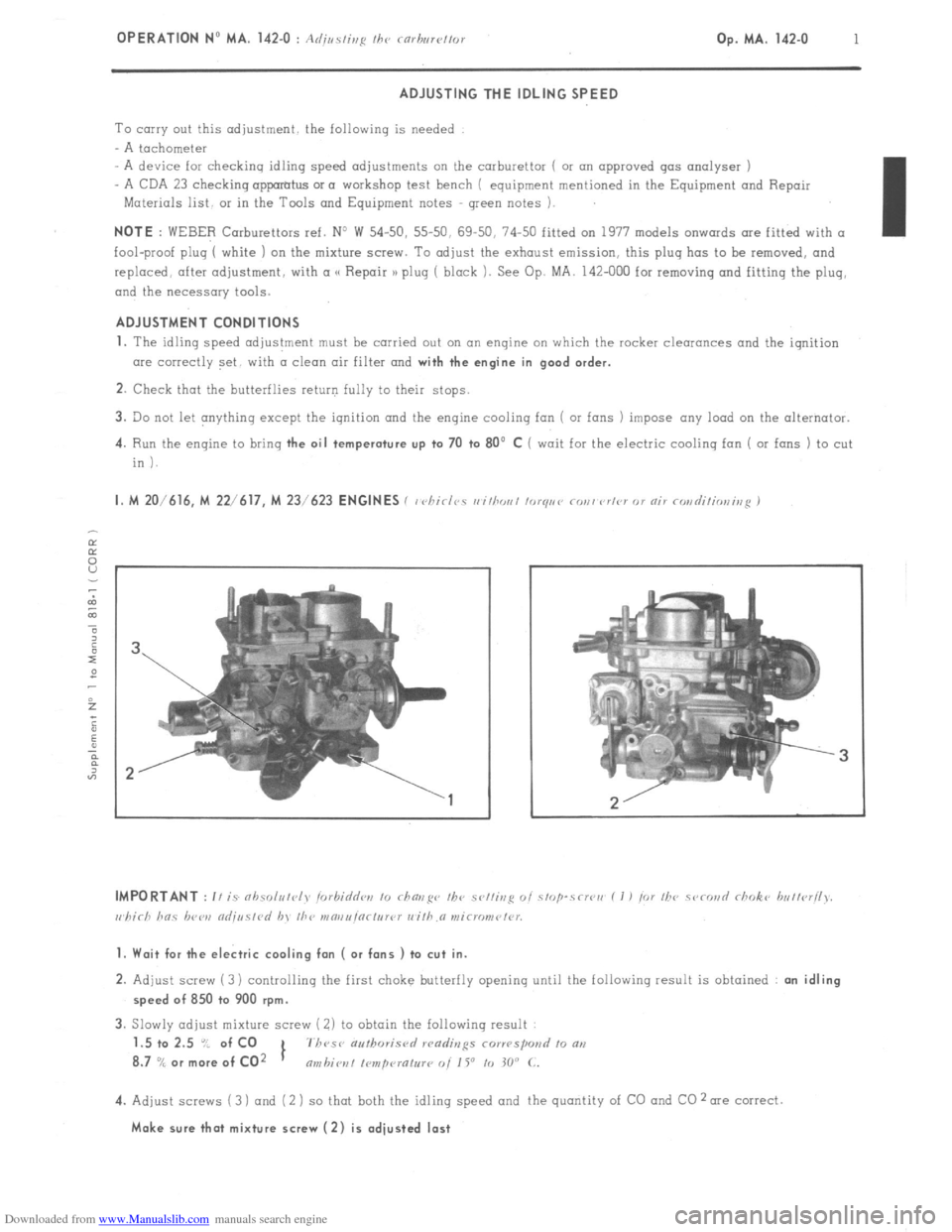
2. Adjust screw (3) controlling the first choke butterfly opening until the following result is obtained : an idling
speed of 850 to 900 rpm.
3. Slowly adjust mixture screw ( 2) to obtain the following result
1.5 to 2.5 “/ of CO
1 7h~se authoris<,
8.7
% or more of CO2 nmbiot~l I~mpcuatur~ 0i 1 Y to 30” C.
4. Adjust screws (3 ) and (2 ) so that both the idling speed and the quantity of CO and CO 2 me correct.
Make sure that mixture screw (2) is adjusted last
Page 92 of 394
Downloaded from www.Manualslib.com manuals search engine OPERATION No MA. 142-O SD : (I k’ II c ,r,g m,d or/j,,r/ii,,~ /he m/i /dllllior, 5, Cl<‘,,i Op. MA. 142-O SD 1
f SIi’III)ISH \IAKKl:‘/ ,‘1,,,( 1.1’) ,
CHECKING THE SAFETY DEVICE FOR THE CHOKE i ( ?XO ,
2 1. Electrical components :
z
a Switch on the ignition
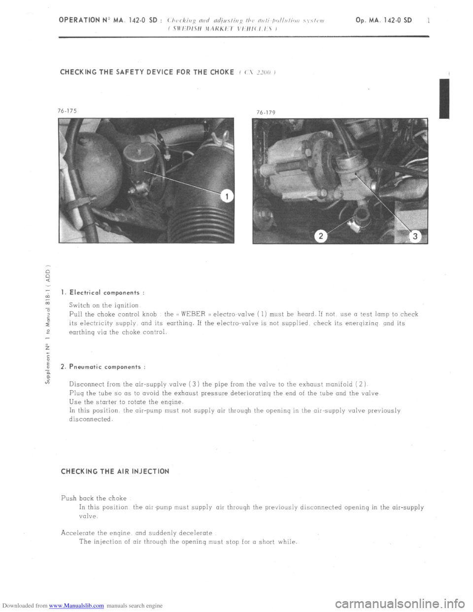
4 Pull the choke control knob the CC WEBER a) electto-valve ( 1) must be heard. If not use a test lamp to check
its electricity supply and its earthing. If the electro-valve is not supplied. check its energizinq and its
2
earthinq via the choke control.
5
;
E
; 2.P neurotic components :
?
“7
Disconnect from the air-supply valve ( 3 ) the pipe from the valve to the exhaust manifold ( 2 j
Plug the tube so as to avoid the exhaust pressure deteriorating the end of the tube and the valve
Use the starter to rotate the engine.
In this position the air-pump must not supply air through the opening in the air-supply valve previously
disconnecied.
CHECKING THE AIR INJECTION
Push bock the choke
In this position the air pump must supply air throuqh the previously disconnected opening in the air-supply
valve.
Accelerate the enqine. and suddenly decelerate
The injection of air through the openinq must stop for a short while.
Page 94 of 394
Downloaded from www.Manualslib.com manuals search engine CHECKING THE SAFETY DEVICE FOR THE CHOKE
f (.X 2000 j :
1. Electrical components :
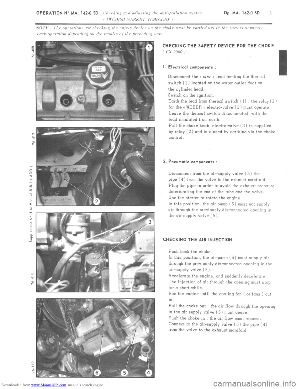
Disconnect the u blur )) lead feeding the thermal
switch (1) located on the water outlet duct on
the cylinder head.
Switch on the ignition.
Earth the lead from thermal switch ( 1) the relay ( 2 )
for the << WEBER 1) electro-valve ( 3) must operate.
Leave the thermal switch disconnected with the
lead insulated from earth.
Pull the
choke knob. electro-valve (3) is supplied
by relay (2 ) and is closed by earthing via the choke
control.
2. Pneumatic components :
Disconnect from the air-supply valve ( 5) the
pipe (4) from the valve to the exhaust manifold.
Plug the pipe in order to avoid the exhaust pressure
deteriorating the end of the tube and the valve
Use the starter to rotate the engine.
In this position. the air pump (6 j must
not supply
air through the previously disconnected opening in
the air supply valve ( 5)
CHECKING THE AIR INJECTION
Push back the choke
In this position. the air-pump (6 ) must supply air
through the previously disconnected opening in the
air-supply valve ( 5 1.
Accelerate the engine, and suddenly decelerate
The injection of air throuqh the opening must stop
for a short while.
Run the engine until the cooling fan ( or fans ) cut
in.
Pull the choke out : the air flow through the opening
in the air supply valve ( 5) must cease.
Push the choke in : the air flow must resume.
Connect to the air-supply valve ( 5) the pipe ( 4 )
from the valve to the exhaust manifold.
Page 112 of 394
Downloaded from www.Manualslib.com manuals search engine OPERATION No MA.IE. 144-00 : Chnract~~ristics o/ the H I,-jctrortic P dectrnr~ir
/i/c,1 iujcctim splcm. Op. MA.IE. 144-00 17
SUPPLEMENTARY AIR CONTROL ( 1 ) :
I’ / -...’ , _, ._,, ! .’ ! . .
At idling speed and when cold, the engine must produce more torque so as to counteract increased resistance
caused by friction. In addition to an enriched air fuel mixture, the engine also needs, when starting from cold
and during the warming-up period, to be supplied with supplementary air. The E.C.U. compensates for this
supplementary air by providing more fuel; the engine therefore has a larger amount of mixture at its disposal
to reach normal running temperature. The supplementary air control fitted in parallel with the throttle butterfly
supplies the supplementary air. The supplementary air control is heated only when the engine is running, and
its heater winding is supplied electrically as long as the ignition is switched on.
The location of the supplementary air control ‘on the engine block was selected for its good heat transfer charac-
teristics, and so as to subject the unit to the changing ambient temperature of the engine.
The opening section of the supplementary air control is automatically .adjusted according to the temperature, so
that the required idling speed is maintained regardless of engine temperature. When the latter increases, the air
channel is gradually reduced, until it is completely closed when the coolant temperature reaches approximately
+ 60” C. ->.:.. .-. : --.
,
The supplementary air control is situated at a representative spot fo.r engine running temperature. A bi-metal
spring actuates a rotary valve thereby altering the size of the air passage. Electric heating has the advantage
of allowing the. supplementary air to be adjusted at pre-set times. SWITCH ON THROTTLE BUTTERFLY SPINDLE :
,‘1 3 >_
The switch on the throttle butterfly spindle contains two contacts the idling speed contact, and the.full load contact.
The control contact, which.slides along a slot, closes the idling speed contact or the full load contact for a given
position of ‘the butterfly. The’ E.C.U. analyses the signals received so as to adjust the duration of injection.
Page 113 of 394
Downloaded from www.Manualslib.com manuals search engine ELECTRIC PETROL PUMP
The petrol pump is of the multi roller-vane type, driven by an electric motor which is energized as long as the
ignition is switched on. The rotor, which is fitted eccentrically in the pump housing, has metal roller vanes in
grooves around t.he periphery which, when they are forced outwards under the action of the centrifugal force, ensure
the system-is sealed.
Fuel is drawn into the cavities which,appear in between the roller-vanes, and is then forced into the injection
piping.
The electric motor is submerged’ in fuel. However, there .is no fire risk, since there is never any combustible
mixture in the pump housing. The pump supplies more fuel than the engine consumes under full load, so that
there is always sufficient pressure in the fuel system, whatever the engine speed. Excess fuel flows back to
the tank.
Once the ignition is on, the pump operates at the same time as the starter motor. Once the engine is running, the
airflow sensor energizes the pump.
Thanks to this type of.system, if an injector is faulty ( leaks ) the cylinder in question cannot be flooded if one
has ommitted to switch the ignition off. PETROL FILTER (1) :
A fuel filter, fitted between the pump and the injectors, prevents any impurities from reaching the injectors. PETROL PRESSURE REGULATOR ( 2 ) :
The fuel pressure is maintained constant by the pressure regulator. It comprises a metal housing
is a diaphragm., One side of the dipphragm.is subjected to the fuel under pressure, and the other 2
to the action of a calibrated spring. inside which
side is subjected
When the fuel pressure is in excess of 2 bars ( 29 psi ), the diaphragm lifts and allows fuel to flow back to the
tank.
The pressure provided by the regulator is pre-adjusted at the factory. The chamber on the side of the spring is
connected via a flexible pipe to the inlet manifold. Therefore, the difference between the pressure in the inlet
manifold and that of the fuel is maintained constant.
For any engine load, the drop in pressure at the injectors is therefore the same.
Page 116 of 394
Downloaded from www.Manualslib.com manuals search engine Op. MA.IE. 144-O 1 I - PRECAUTIONS TO BE TAKEN WHEN WORKII;(G ON A VEHICLE FITTED WITH THE (t L-JETRONIC n
SYSTEM.
1.
Do not run the engine if the battery leads are improperly secured
2. Do not use a quick-start charging trolley for starting the engine
3. Never disconnect the battery with the engine running
4. When charging the battery, disconnect the leads
5. Before checking the injection system, check the ignition : (advance, advance curve, proper grade of plugs 1
6. Remove the E C U before putting the vehicle through a paint-stoving oven
7. Check the conditions of the various connections
8. Never disconnect the E,C U. while the ignition is on
9. When checking compression, disconnect the positive terminal of the coil (in order to stop the injection signal). 10.
When carrying out a check requiring an ohmmeter, use exclusively a battery-powered ohmmeter. II. FAULT-FINDING.
1. THE ENGINE DOES NOT START, OR IS DIFFICULT TO START . . . . . . . . . . . . . . . . . . . . . . . . . . . . . . . . . . . . . . . . . . . . . . . . . . . . . . . . P. 2
2. THE ENGINE STARTS, THEN STOPS . . . . . . . . . . . . . . . . . . . . . . . . . . . . . . . . . . . . . . . . . . . . . . . . . . . . . . . . . . . . . . . . . . . . . . . . . . . . . . . . . . . . . . . . . . . . . . . . . . . . . . P. 3
3. UNSTABLE OR INCORRECT IDLING SPEED, EXCESSIVE FUEL CONSUMPTION ........................ P:5
-4. ENGINE MISFIRES AT .ALL SPEEDS ........................................................................................................
P. 7
5. LACK OF POWER . . . . . . . . . . . . . . . . . . . . . . . . . . . . . . . . . . . . . . . . . . . . . . . . . . . . . . . . . . . . . . . . . . . . . . . . . . . . . . . . . . . . . . . . . . . . . . . . . . . . . . . . . . . . . . . . . . . . . . . . ................ P. 9