ignition Citroen CX 1976 1.G User Guide
[x] Cancel search | Manufacturer: CITROEN, Model Year: 1976, Model line: CX, Model: Citroen CX 1976 1.GPages: 394
Page 131 of 394
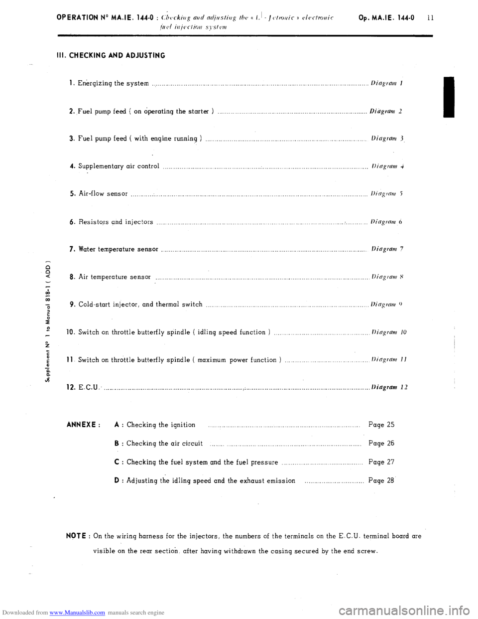
Downloaded from www.Manualslib.com manuals search engine Ill. CHECKING AND ADJUSTING
1
. Energizing the system ..................................................................................................................
2. ,Fuel pump feed ( on operating the starter ) .............................................................................
3. Fuel pump feed ( with engine running ) ...................................................................................
4. Supplementary air control ...........................................................................................................
5. Air-flow sensor ............................................................................................................................
6. Resistors and injectors ................................................................................................... . ........
7. Water temperature sensor ............................................................................................................ .
Dingram 7
8. Air temperature sensor ...............................................................................................................
9. Cold-start injector, and thermal switch ...................................................................................
10. Switch on throttle butterfly spindle ( idling speed function ) ............................................ 11
Switch on throttle butterfly spindle ( maximum power function ) ...................................... 12.
E.C.U: ......................................................................... ..~ ............................................................... . . Diagram 1 I ANNEXE : A
: Checking the ignition .................................................................................. Page 25 B
: Checking the air circuit ................................................................................ Page 26
C : Checking the fuel system and the fuel pressure ........................................... Page 27 D
: Adjusting the idling speed and the exhaust emission .............................. Page 28 NOTE
: On the wiring harness for the injectors, the numbers of the terminals on the E.C.U. terminal board are
visible on the rear section. after having withdrawn the casing secured by the end screw.
Page 132 of 394
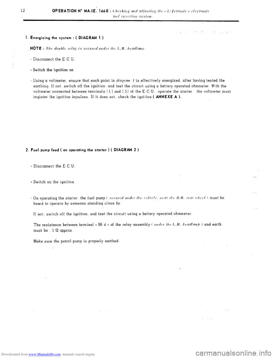
Downloaded from www.Manualslib.com manuals search engine 1. Energizing the system : ( DIAGRAM 1 )
_ Disconnect the E.C U
- Switch the ignition on
Using a voltmeter. ensure that each point in
dingrm 1 is effectively energised. after having tested the
earthing. If not, switch off the ignition. and test the circuit using a battery operated ohmmeter. With the
voltmeter connected between terminals ( 1 ) and ( 5) of the E. C.U., operate the starter the voltmeter must
register the ignition impulses If it does not. check the ignition
( ANNEXE A ).
2. Fuel pump feed ( on operating the starter ) ( DIAGRAM 2 )
- Disconnect the E C.U.
- Switch on the ignition
- On operating the starter. the fuel pump (
secureri rrt/rler the I c~hiclc’. uoor IIJO K. ti. ronr (, l~eol I must be
heard to operate by someone standing close by
If not switch off the ignition, and test the circuit using a battery operated ohmmeter.
The resistance between terminal (( 88 d H of the relay assembly ( c~r~tler 111~
L,H. honr/llor)~p ) and earth
must be 1 Q approx-
Make sure the petrol pump is properly earthed.
Page 135 of 394
Downloaded from www.Manualslib.com manuals search engine Op. MA.IE 444-O 15
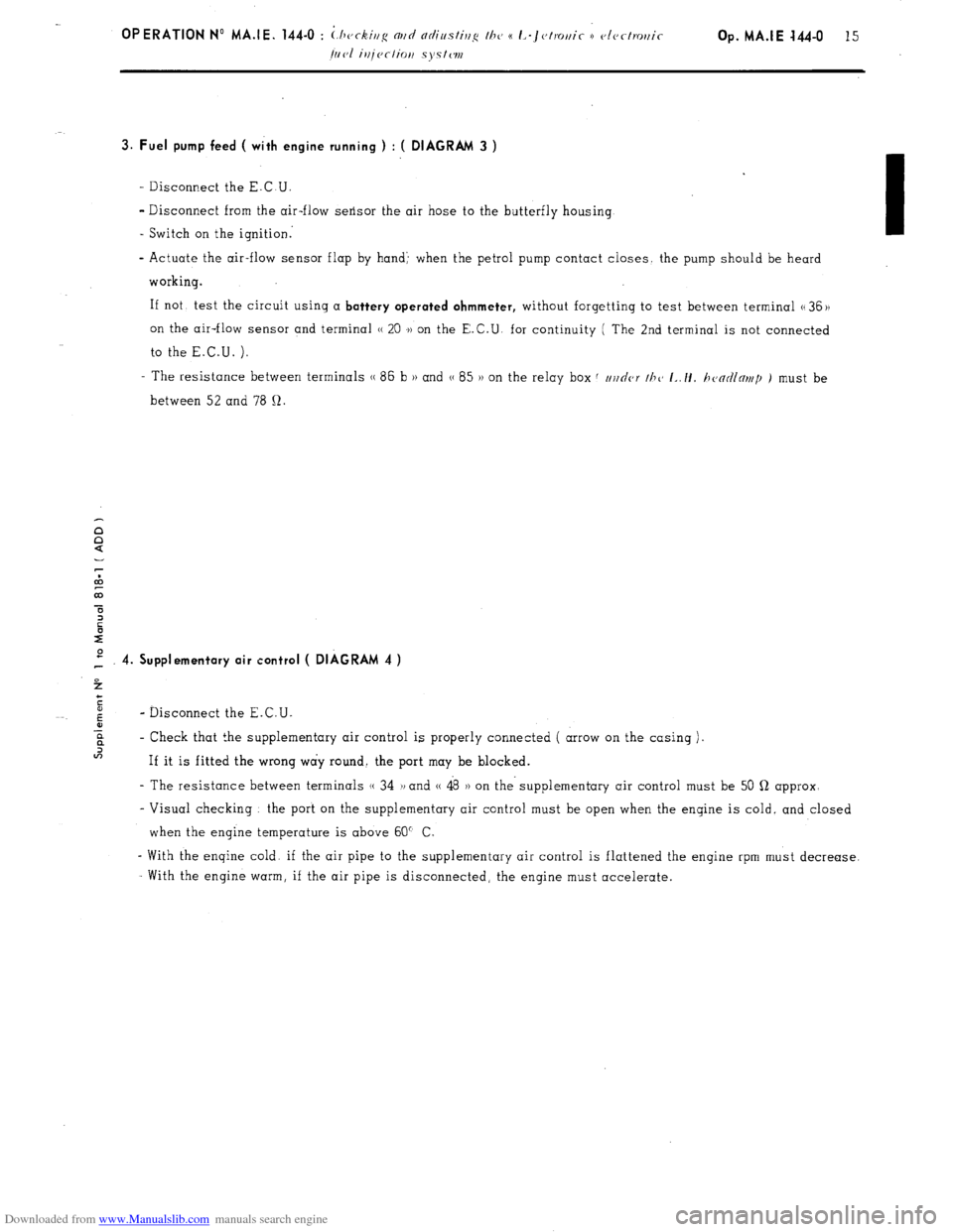
3. Fuel pump feed ( with engine running ) : ( DIAGRAM 3 )
- Disconnect the E.C.U.
- Disconnect from the air-flow sensor the air hose to the butterfly housing
- Switch on the ignition:
- Actuate the air-flow sensor flap by hand’ when the petrol pump contact closes the pump should be heard
working.
If not, test the circuit using a
battery operated ohmmeter, without forgetting to test between terminal G 36 ))
on the air-flow sensor and terminal H 20 .)) on the E.C.U. for continuity ( The 2nd terminal is not connected
to the E.C.U. ).
- The resistance between terminals (( 86 b H and G 85 )) on the relay box f //j/nor thc~ I~./I. h<~ntllnr~tp ) must be
between 52 and 78 12.
P 4. Supplementary air control ( DIAGRAM 4 )
4
c
5
6
- Disconnect the E.C.U.
-E
? - Check that the supplementary air control is properly connected ( arrow on the casing )~
In
If it is fitted the wrong way round. the port may be blocked.
- The resistance between terminals (( 34 1, and (( 48 )) on the- supplementary air control must be 50 Q approx-
- Visual checking the port on the supplementary air control must be open when the engine is cold, and closed
when the engine temperature is above 60” C
- With the engine cold. if the air pipe to the supplementary air control is flattened the engine rpm must decrease.
With the engine warm, if the air pipe is disconnected, the engine must accelerate.
Page 140 of 394
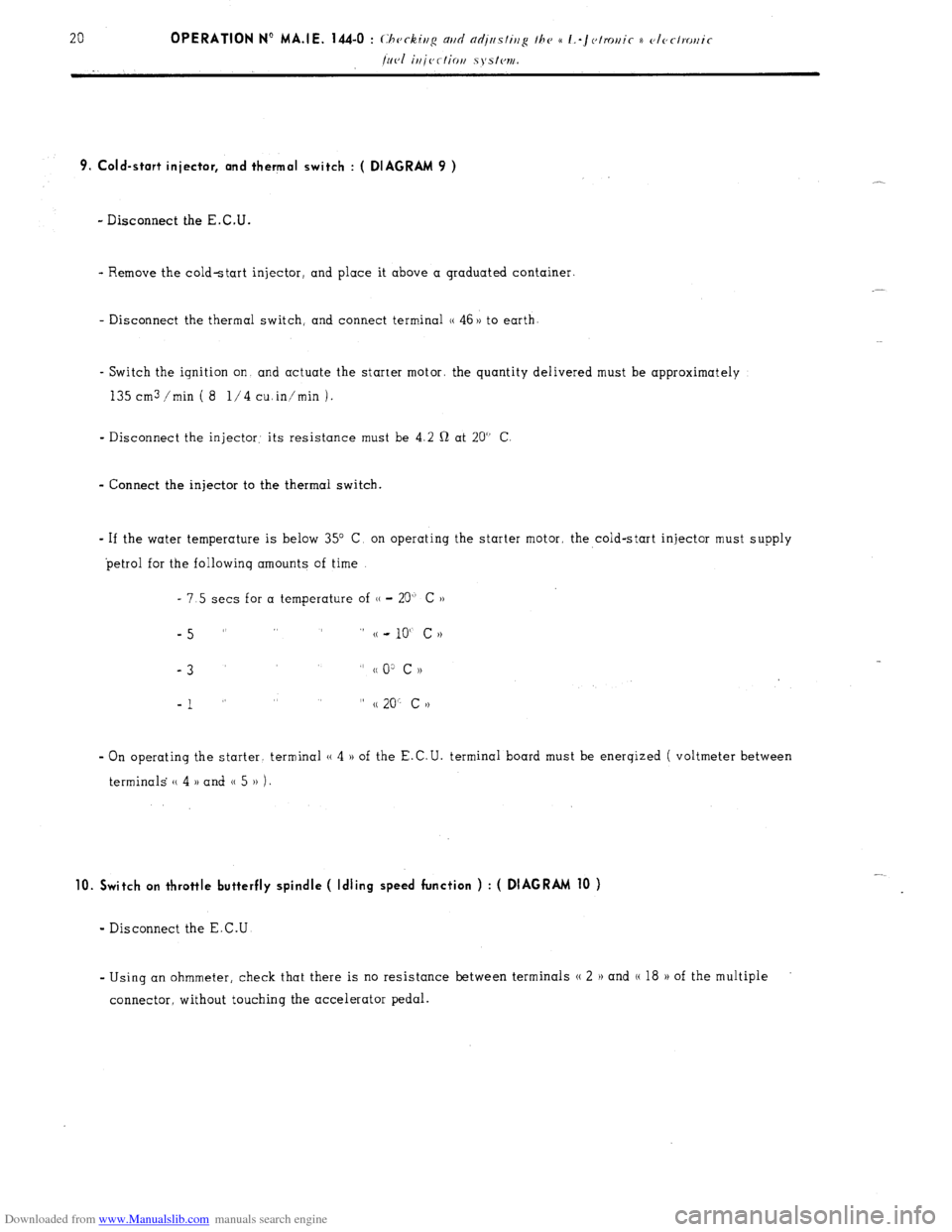
Downloaded from www.Manualslib.com manuals search engine 9. Cold-start injector, and thermal switch : ( DIAGRAM 9 )
- Disconnect the E.C.U.
- Remove the cold-start injector, and place it above a graduated container.
- Disconnect the thermal switch, and connect terminal (( 46 )) to earth
- Switch the ignition on and actuate the starter motor. the quantity delivered must be approximately
135 cm3 /min ( 8 l/4 cuin’min 1.
- Disconnect the injector: its resistance must be 4.2 Q at 20” C
- Connect the injector to the thermal switch.
- If the water temperature is below 35” C, on operating the starter motor, the cold-start injector must supply
petrol for the followinq amounts of time
- 7.5 sets for a temperature of (( - 20” C ))
-5 ” ” (( - 10“ c N
-3
” cc 0: c ))
-1 ” ” (( 20” c >)
- On operating the starter. terminal (( 4 )) of the E.C.U. terminal board must be enerqized ( voltmeter between
terminals (( 4 )) and 0 5 )) 1.
10. Switch on throttle butterfly spindle ( Idling speed function ) : ( DIAGRAM 10 )
- Disconnect the E.C.U
- Using an ohmmeter, check that there is no resistance between terminals N 2 H and (( 18 H of the multiple
connector, without touching the accelerator pedal.
Page 145 of 394

Downloaded from www.Manualslib.com manuals search engine OPERATION No MA.IE. 144-0 : (,hcrkir~g m/cl nrl;tts/ir/<~ I/W a I.-J~~/m,i~ ~~otectrot,ic Op. MA.IE. 144-O 25 fi~cl irijection systc~rti.
ANNEXE : A - CHECKING THE IGNITION
THE ENGINE TURNS, BUT DOES
NOT FIRE
Page 149 of 394
Downloaded from www.Manualslib.com manuals search engine 28 OPERATION N” MA.IE. 144-O : Ch <,c ,ng n,,d nlfjusfiup Ihe u I.-~<~tro,,ir i) <~lrr/mr,ir k’
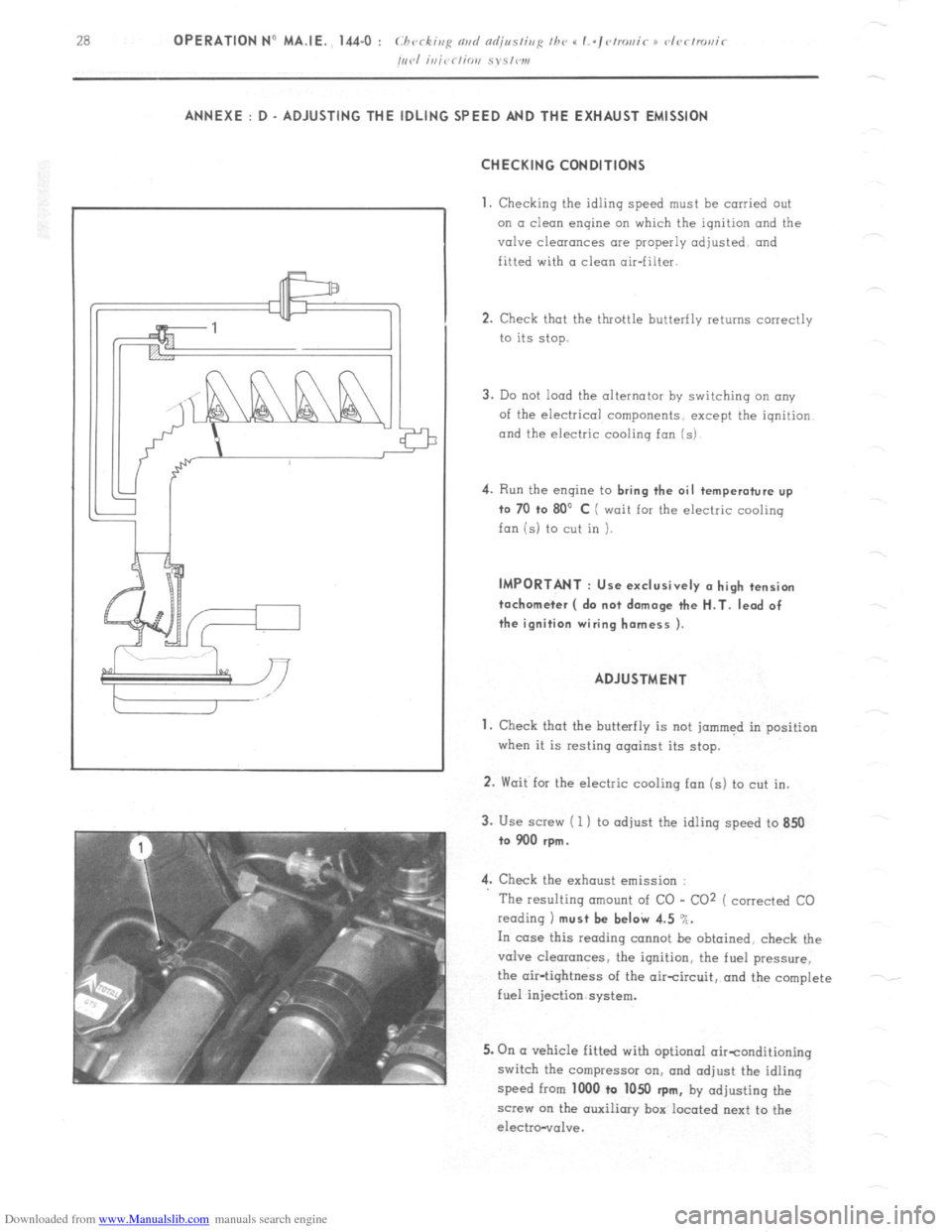
/,,,.I i,,jrr/io,, S~S,W1, ANNEXE : D - ADJUSTING THE IDLING SPEED AND THE EXHAUST EMISSION
CHECKING CONDITIONS
1.
Checking the idling speed must be carried out
on a clean engine on which the ignition and the
valve clearances are properly adjusted and
fitted with a clean air-filter.
2. Check that the throttle butterfly returns correctly
to its stop.
3. Do not load the alternator by switching an any
of the electrical components, except the iqnition
and the electric cooling fan (s) 4.
Run the engine to bring the oil temperature up
to 70 +o 80’ C ( wait for the electric cooling
fan is) to cut in ). IMPORTANT : Use exclusively (I high tension
tachometer ( do not damage the H.T. lead of
the ignition wiring harness ).
ADJUSTMENT
1. Check that the butterfly is not jammed in position
when it is resting against its stop.
2. Wait for the electric cooling fan (s) to cut in.
3. Use screw ( 1 ) to adjust the idling speed to 850
to 900 rpm.
4. Check the exhaust emission :
The resulting amount of CO - CO2 ( corrected CO
reading 1 must be beI& 4.5 %.
In case this reading cannot be obtained, check the
valve clearances, the ignition, the fuel pressure,
the air-tightness of the aircircuit, and the complete
fuel injection system.
5. On (I vehicle fitted with optional oirtonditioning
switch the compressor on, and adjust the idling
speed from 1000 to 1050
rpm, by adjusting the
screw on the auxiliary box located next to the
electro-vol”e.
Page 152 of 394
Downloaded from www.Manualslib.com manuals search engine IGNITION
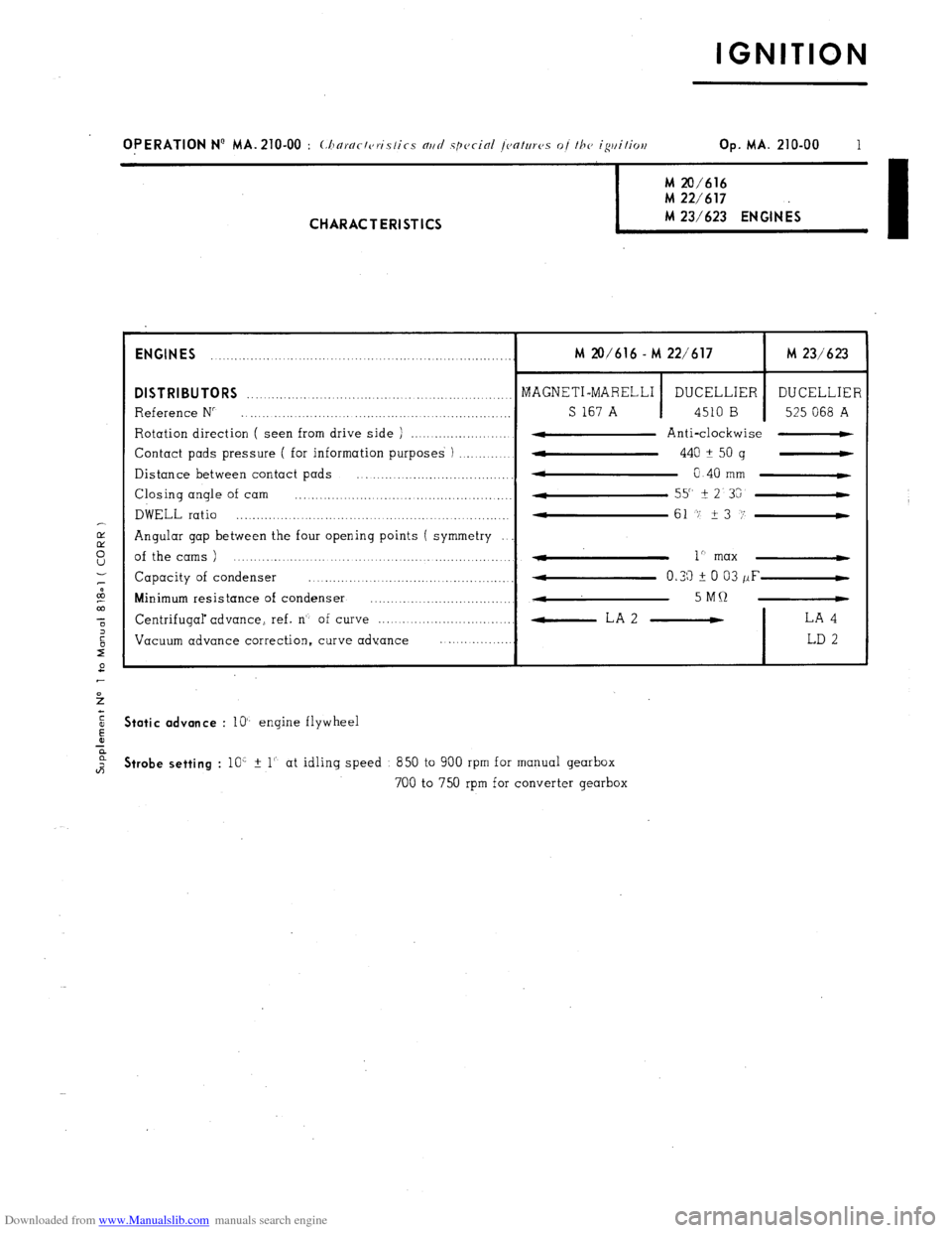
OPERATION N’ MA. 210-00 : (:horr/r/c,ri.s/ics nrtrl spccinl /C,O/UTCJS of /he igtti/ioe Op. MA. 210-00 1 M 20/616
M 22/617 M 23/623 ENGINES
I CHARACTERISTICS
ENGINES
........ ........... ................................................. M 20/616 - M 22/617 M 23/623
DISTRIBUTORS ........................................... MAGNETI-MARELLI _._ ..............
DUCELLIER DUCELLIER
Reference N” ........................... .., ............................. _._ S 167 A 4510 B 525 068 A
Rotation direction ( seen from drive side ) ....................... 4 Anti-clockwise -
Contact pads pressure ( for information purposes ) ..............
w 440 A
50 g -
Distance between contact pads
* ................................... 0 40 mm C
Closing angle of cam ................... .................................. 55" It
2 3G
DWELL ratio ............................................... 4
....... .......... 61 -7 23 i’-
Angular gap between the four opening points ( symmetry
of the cams ) ....................................................... - 1” max 4
Capacity of condenser ......... ... ............... ...... ........ 4 0.33 i 0 03 /IF-
Minimum resistance of condenser ...............................
., ...
4 5MQ -
Centrifugal advance, ref. n’- of curve ................................. -LA2 - LA 4
Vacuum advance correction, curve advance ..................
LD 2 Static advance
: lo’- engine flywheel Strobe setting
: 10’ % 1’. at idling speed 850 to 900 rpm for manual gearbox
700 to 750 rpm for converter gearbox
Page 153 of 394
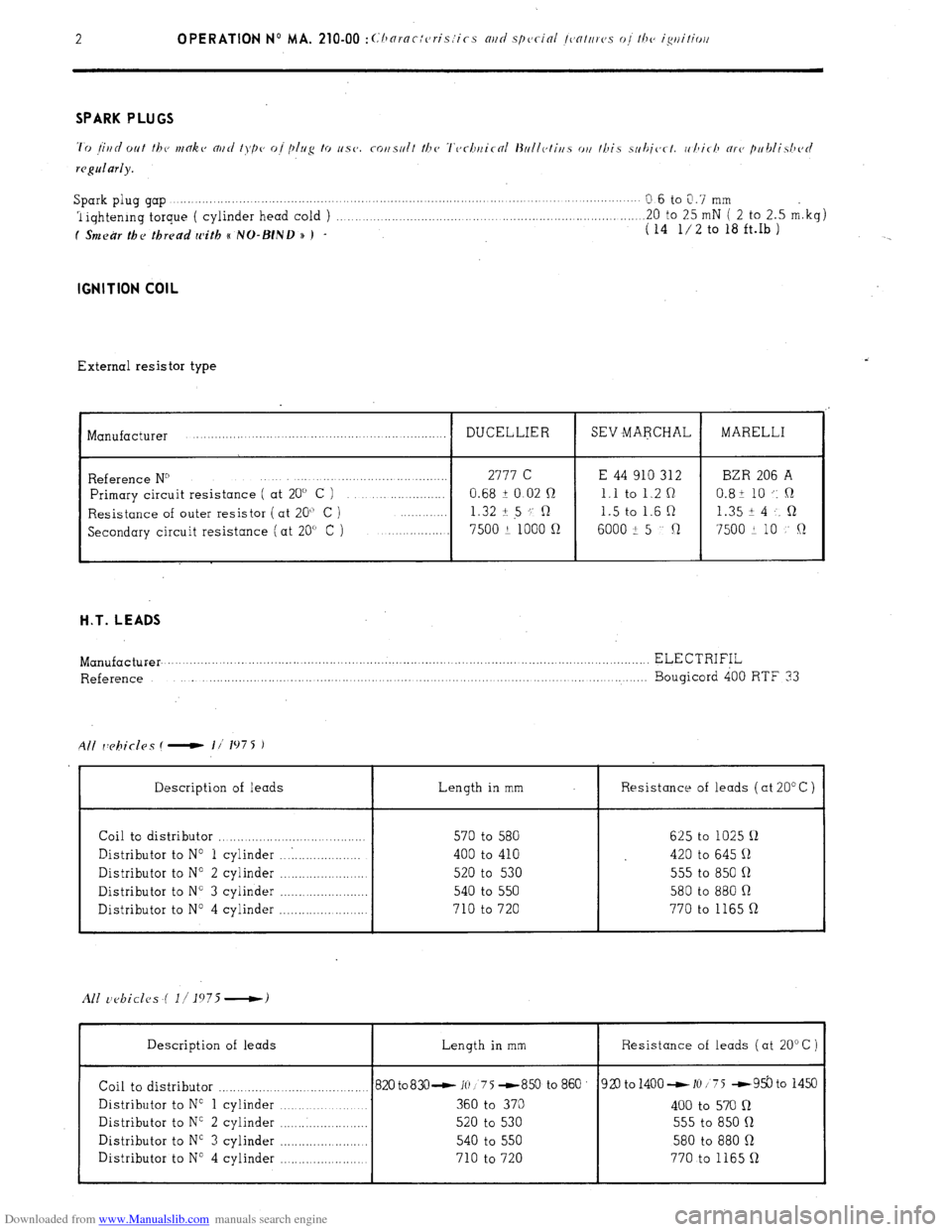
Downloaded from www.Manualslib.com manuals search engine 2 OPERATION No MA. 210-00 :~~‘hornc:cris:ics mri special /~~nttrrc,.s o,/ /he ig/litiorl Spark plug gap .,...._.......,...,. ,..._. ,...... ., ,, ,,
Q.6 to 0.7 mm
1 iqhtenrng torque ( cylinder head cold ) .._..._._........._.......... .20 to 25 mN ( 2 to 2.5 m.kg)
f Smear the thread with e NO-BIND n ) - ( 14 l/2 to 18 ft.Ib ) IGNITION COIL
External resistor type
I Manufacturer
I DUCELLIER
I SEV MARCHAL
I MARELLI
Reference N” 2777 C E 44 910 312 BZR 206 A
Primary circuit resistance ( at 20” C ) 0.68 i 0.02 n 1.1 to 1.2 Q 0.8+ 10 .: ,R
Resistance of outer resistor (at 20” C ) 1.32 + 5 ‘; R 1.5 to 1.6 R 1.35 i 4 . . R
Secondary circuit resistance (at 20” C ) 7500 2 1000 n
6000 -!I 5 Cl 7500 + 10 !’ Q H.T. LEADS
Length in mm Resistance of leads ( at 20” C )
Manufacturer. .................. .......................................................... ..................................................... ELECTRIFIL
Reference ..................... ............. ........... ....... ....... ... ........................ ............ ......... Bougicord 400 RTF 33
All rY?biclas ( - I/’ 1975 1
Description of leads
Coil to distributor ............................ ...........
Distributor to No 1 cylinder ... . ..................
Distributor to No 2 cylinder .......................
Distributor to N” 3 cylinder ........................
Distributor to N” 4 cylinder ........................ 570 to 580 625 to 1025 !J
400 to 410 420 to 645 11
520 to 530 555 to 850 11
540 to 550 580 to 880 Q
710 to 720 770 to 1165 Q
I I I
Description of leads Length in mm
I Resistance of leads ( at 20” C )
Coil to distributor ......................................... 820 to83O- 10 1 75 -859 to 860
Distributor to No 1 cylinder ..................... 360 to 370
Distributor to N” 2 cylinder ........................ 520 to 530
Distributor to NC 3 cylinder ....................... 540 to 550
Distributor to N” 4 cylinder
...................... 710 to 720 920 to 1400 - 10 175 -93.3 to 1450
400 to 570 n
555 to 850 R
580 to 880 Q
770 to 1165 Q
I I 1
Page 154 of 394

Downloaded from www.Manualslib.com manuals search engine OPERATION No MA. 210-W 0 : Ch araclcrislics ~3rd spcial /W~~NWS 0j thr d~~fmt~i~ Op. MA. 210-00 a 1
ipith syslwn.
I
M 23/622 ENGINE
TRANSISTORISED IGNITION WITH ELECTROMAGNETICALLY CREATED IMPULSES
$ OPERATING PRINCIPLE
?
:
I
,D The electronic ignition comprises a coil ( 1 1. (I transistorised module ( 2) which includes among other components.
-
.f a power transistor working as a contact breaker.
and a distributor (3 1 with a magnetic pick-up ( impulse generator )
and an H.T. rotor.
;
ii
:
F The primary current from the coil goes through a switching transistor situated in the module ( the earthing is carried
“7
out via the fixing bracket for the coil mrd module assembly ).
As an impulse is created by the sensor in the distributor. it switches off the transistor and thus cuts off the flow
of current in the coil primhry circuit. which causes a (< High Tension 1) current in the coil secondary circuit.
The module is located in the distributor..replocinq the contact breaker unit in a conventional ignition system. It
comprises a sensor (4) and a 4-point star ( 5 ).
The,sensor has a permanent moqnet inside a winding. This windinq is connected electrically to the module
I
/
The 4-point star is made of metal. and has one star per cylinder. It is fitted in place of the rotor mm cam in (I
conventional ignition system.
Page 155 of 394
Downloaded from www.Manualslib.com manuals search engine CHARACTERISTICS
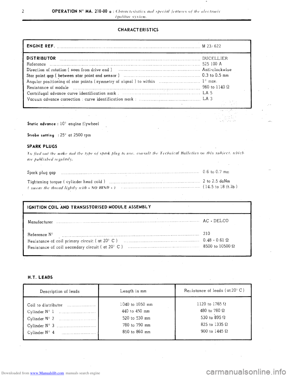
ENGINE REF.
........................................................................................... ........................ M 23/ 622
DISTRIBUTOR DUCELLIER ..................................................................................................................
Reference ..................................................................................................................... 525 100 A
Direction of rotation ( seen from drive end ) . .................................................................
Anti-clockwise
Star point gap ( between star point and sensor ) .............................................................. 0.3 to 0.5 mm
Angular positioning of star points ( symmetry of signal ) to within ........... ... ... ....... ..... 1” max.
Resistance of module 960 to 1140 fi .................................................................................................. Centrifugal
advance curve identification mark ................................. . ..................... LA 5
Vacuum advance correction
curve identification mark : ..................................................
LA 3 Static advance
: 10” engine flywheel . .’ Strobe setting
: 25’ at 2500 rpm SPARK PLUGS
Spark plug gap ................. ....
.................... ................... ....... 0.6 to 0.7 mm
......................... .........
Tightening torque ( cylinder head cold ) ....................................................................
2 to 2.5 daNm
( spl,(,c,)’ //T(, /hrc,nc/ /ig/T//>f cc,i//T H ,VO J~/,N/) )) ) ...................................................... (14.5 to 18 ft.lb )
I IGNITION COIL ‘AND TRANSISTORISED MODULE ASSEMBLY
I
Manufacturer ...............
................... ........ .............. .............. .......
AC - DELCO
...........................
Reference N” 210
....................................................... ...
....................................................
Resistance of coil primary circuit ( at 205 C ) ............................................................ 0.48 - 0.61 R
Resistance of coil secondary circuit ( at 20” C ) ......................................................... 8500 to 10500 fl H.T. LEADS
Description of leads Length in mm
Coil to distributor ....................... 1040 to 1050 mm
Cylinder N” 1 ............................ 440 to 450 mm
Cylinder N” 2 ............................. 520 to 530 mm
Cylinder N” 3 ................................ 780 to 790 mm
Cylinder No 4 850 to 860 mm
............................ Re:;istance of leads ( at 20L C )
I
1120 to 1765 (1
480 to 780 Q
530 to s95 Q
825 to 1335 Q
900 to 1445 R