sensor Citroen CX 1977 1.G User Guide
[x] Cancel search | Manufacturer: CITROEN, Model Year: 1977, Model line: CX, Model: Citroen CX 1977 1.GPages: 394
Page 136 of 394
Downloaded from www.Manualslib.com manuals search engine 5. Air-flow sensor ( DIAGRAM 5 )
- Disconnect the E.C.U.
- Using an ohmmeter check the continuity of circuits (( 6 )a, H 7 )) (( 8 H and (( 9 )) linking the air-flow sensor to
the multiple terminal board. as well as the continuity between each of the terminals
- The air-flow meter does not require any maintenance. It is not necessary to oil the flop. It must work without
high spot or catching
When the air-flow sensor is removed blank off the ducts so OS to protect it from dust
- Check the air circuit for air-tightness.
6. Resistors and injectors :
- A dirty injector may cause o lock of power. or on unstable idling speed.
- It is possible to test the functioning of the injectors with the engine idling by disconnecting each injector
in turn the engine rpm should decrease each time.
- Disconnect the E C U
- The resistance of an injector is 2 to 3 II.
- Each supplementary resistance is 5 to 7 R
- The volume delivered by an injector ( kept constantly open and under the normal operating pressure ) is
approximately 200 cm3 /min ( 12 25 cu in/min )-
- If the rubber pipe on one of the injectors appears wet on the outside, the injector must be replaced.
- Using an ohmmeter, check the continuity of the circuits
Page 139 of 394
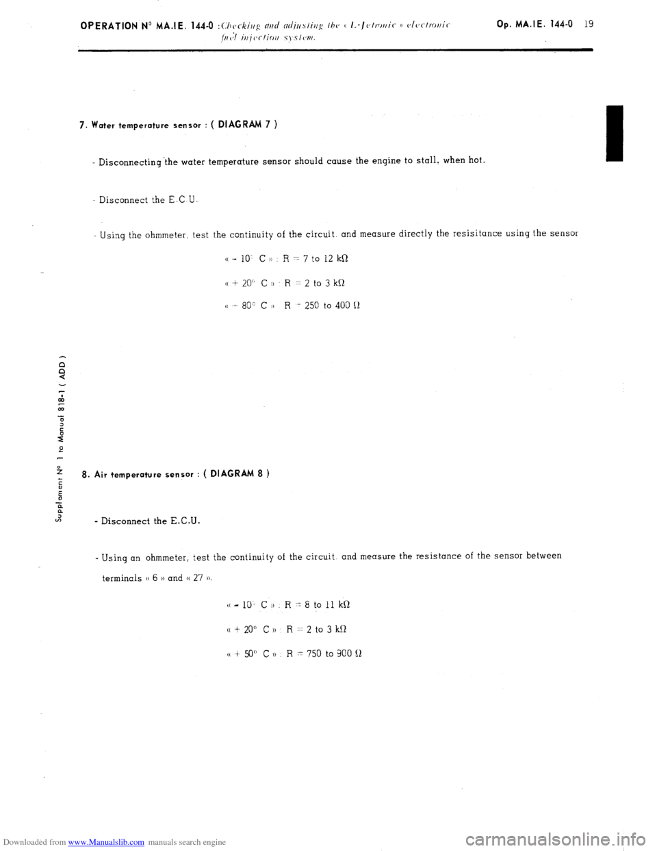
Downloaded from www.Manualslib.com manuals search engine 7. Water temperature sensor : ( DIAGRAM 7 )
- Disconnecting ‘the water temperature sensor should cause the engine to stall. when hot.
- Disconnect the E.C U
Using the ohmmeter, test the continuity of the circuit. and measure directly the resisitance using the sensor
cc - 10’ C )) R = 7 to 12 kR
cc + 20” C )t R = 2 to 3 kQ
cc t 80” C H R -. 250 to 400 Q
e
2
ii 8. Air temperature sensor : ( DIAGRAM 8 )
E
-E
?
U-J
- Disconnect the E.C.U. -
Using an ohmmeter, test the continuity of the circuit. and measure the resistance of the sensor between
terminals (( 6 )) and (( 27 ))
(c-10’ CH. R-8toIlkQ
N t 20” C 1) R = 2 to 3 kQ
tt + 50” C n R x 750 to 900 !J
Page 142 of 394

Downloaded from www.Manualslib.com manuals search engine DIAGRAM 11
_____ -------------_--------- -------_.
‘>*
i-- _.
5!L 17. '
i'
/- . uij
-----,'
DIAGRAM 12.
-I
Air-flow sensor Switch on throttle
butterfly spindle
r----- _____ -__----------- t
Multi-stage
control, vibrator t Multiplying
stage
t m Relav
box ‘
.g Additional
2
resistors Y I
switch
Magnetically
’ I
triggered distributor Air temp Water temp sensor
sensor
Page 154 of 394

Downloaded from www.Manualslib.com manuals search engine OPERATION No MA. 210-W 0 : Ch araclcrislics ~3rd spcial /W~~NWS 0j thr d~~fmt~i~ Op. MA. 210-00 a 1
ipith syslwn.
I
M 23/622 ENGINE
TRANSISTORISED IGNITION WITH ELECTROMAGNETICALLY CREATED IMPULSES
$ OPERATING PRINCIPLE
?
:
I
,D The electronic ignition comprises a coil ( 1 1. (I transistorised module ( 2) which includes among other components.
-
.f a power transistor working as a contact breaker.
and a distributor (3 1 with a magnetic pick-up ( impulse generator )
and an H.T. rotor.
;
ii
:
F The primary current from the coil goes through a switching transistor situated in the module ( the earthing is carried
“7
out via the fixing bracket for the coil mrd module assembly ).
As an impulse is created by the sensor in the distributor. it switches off the transistor and thus cuts off the flow
of current in the coil primhry circuit. which causes a (< High Tension 1) current in the coil secondary circuit.
The module is located in the distributor..replocinq the contact breaker unit in a conventional ignition system. It
comprises a sensor (4) and a 4-point star ( 5 ).
The,sensor has a permanent moqnet inside a winding. This windinq is connected electrically to the module
I
/
The 4-point star is made of metal. and has one star per cylinder. It is fitted in place of the rotor mm cam in (I
conventional ignition system.
Page 155 of 394
Downloaded from www.Manualslib.com manuals search engine CHARACTERISTICS
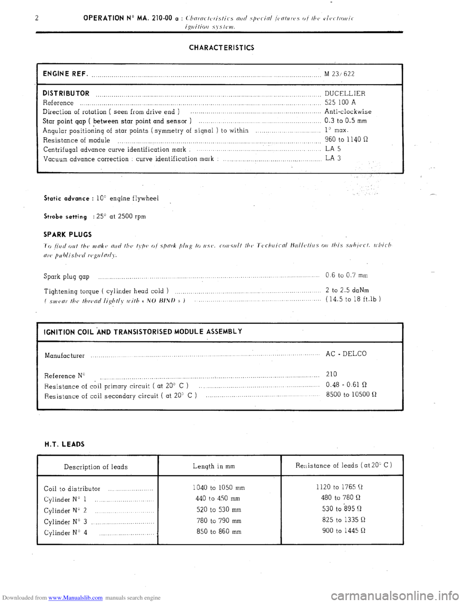
ENGINE REF.
........................................................................................... ........................ M 23/ 622
DISTRIBUTOR DUCELLIER ..................................................................................................................
Reference ..................................................................................................................... 525 100 A
Direction of rotation ( seen from drive end ) . .................................................................
Anti-clockwise
Star point gap ( between star point and sensor ) .............................................................. 0.3 to 0.5 mm
Angular positioning of star points ( symmetry of signal ) to within ........... ... ... ....... ..... 1” max.
Resistance of module 960 to 1140 fi .................................................................................................. Centrifugal
advance curve identification mark ................................. . ..................... LA 5
Vacuum advance correction
curve identification mark : ..................................................
LA 3 Static advance
: 10” engine flywheel . .’ Strobe setting
: 25’ at 2500 rpm SPARK PLUGS
Spark plug gap ................. ....
.................... ................... ....... 0.6 to 0.7 mm
......................... .........
Tightening torque ( cylinder head cold ) ....................................................................
2 to 2.5 daNm
( spl,(,c,)’ //T(, /hrc,nc/ /ig/T//>f cc,i//T H ,VO J~/,N/) )) ) ...................................................... (14.5 to 18 ft.lb )
I IGNITION COIL ‘AND TRANSISTORISED MODULE ASSEMBLY
I
Manufacturer ...............
................... ........ .............. .............. .......
AC - DELCO
...........................
Reference N” 210
....................................................... ...
....................................................
Resistance of coil primary circuit ( at 205 C ) ............................................................ 0.48 - 0.61 R
Resistance of coil secondary circuit ( at 20” C ) ......................................................... 8500 to 10500 fl H.T. LEADS
Description of leads Length in mm
Coil to distributor ....................... 1040 to 1050 mm
Cylinder N” 1 ............................ 440 to 450 mm
Cylinder N” 2 ............................. 520 to 530 mm
Cylinder N” 3 ................................ 780 to 790 mm
Cylinder No 4 850 to 860 mm
............................ Re:;istance of leads ( at 20L C )
I
1120 to 1765 (1
480 to 780 Q
530 to s95 Q
825 to 1335 Q
900 to 1445 R
Page 292 of 394
Downloaded from www.Manualslib.com manuals search engine OPERATION No MA. 510-00 : \m//l‘!yc~tl/ <‘,/I 0 t Ih<’ <‘It,< Ir.itnl iusrtlllnliritt Op. MA. 510-00 3
f 0 lO7i-l,‘1975 )
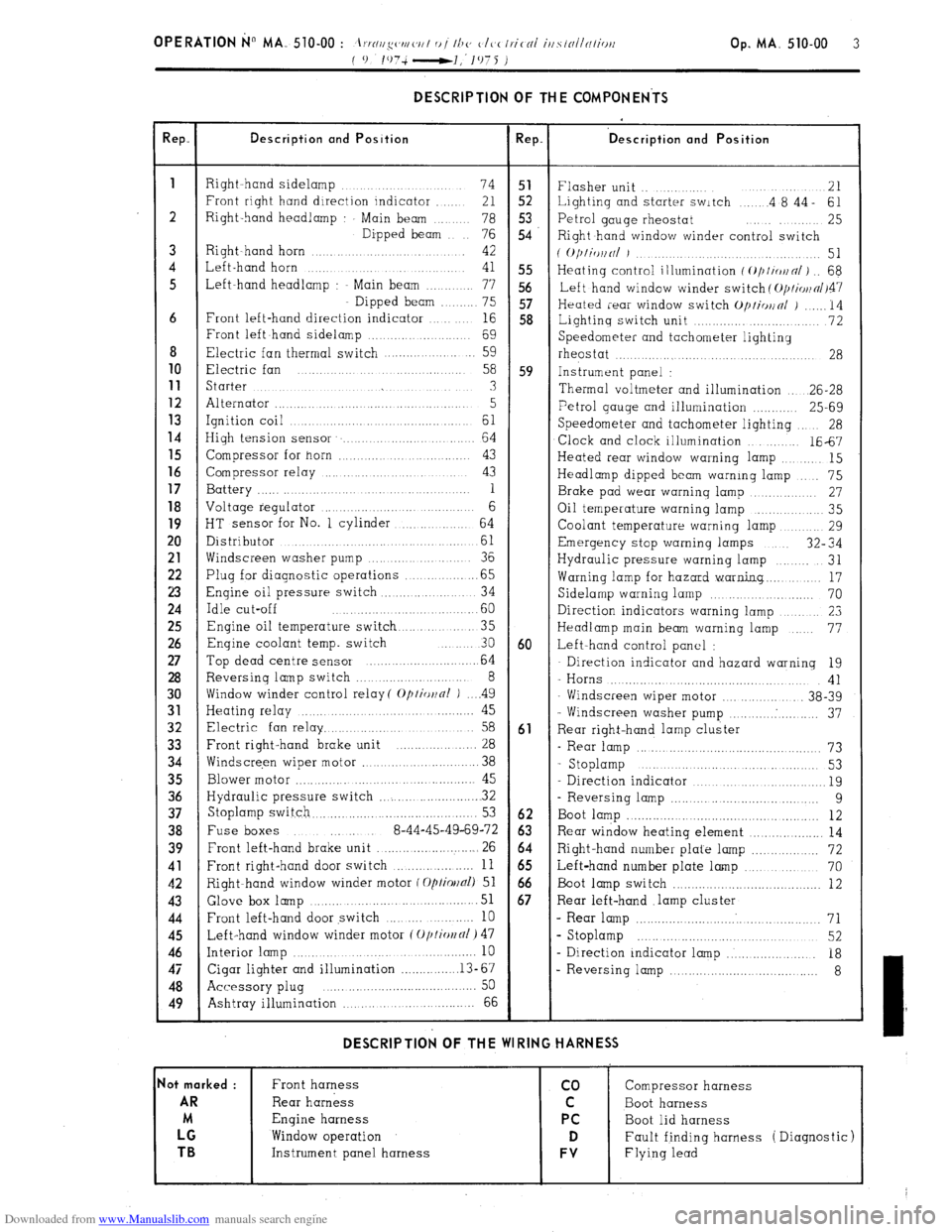
DESCRIPTION OF THE COMPONENTS
!ep. Description and Position Rep. ‘D escription and Position
1
Right hand sidelamp ...... 74 51
Flasher unit .. ....... 21
Front right hand direction indicator ..... 21 52 Lighting and starter switch .... .4 8’44- 61
2 Right-hand headlamp Main beam .. 78 5.3
76 54 Petrol gauge rheostat ........ 25
Dipped beam
Right hand window winder control switch
3 Right~hand horn ............ 42
( O/)liWlNl J ................. 51
4 Left-hand horn ...
41 55 Heating control illumination f ~///io~n/) .. 68
5 Left-hand headlamp : Main beam ....... 77 56
Left hand window winder switch ( O/JI~OII~/~~~
Dipped beam ...... 75 57
Heated rear window switch Op/io~nl j ...... 14
6 Front left-hand direction indicator ... 16 58
Lightinq switch unit ............. ........... 72
Front left hand sidelamp ................. 69
Speedometer and tachometer lighting
8 Electric fan thermal switch .................. 59
rheostat ....... ...... .................... 28 10
Electric fan .......
58 59 Instrument panel : 11
Starter ...... ... .............. .......... 3
Thermal voltmeter and illumination .. 26-28 12
Alternator ............................ ........ 5 13 Petrol gauge and illumination ............ 25-69
Ignition coil ... ......... .............. 61 14
Speedometer and tachometer lighting 28
High tension sensor ....................... 64
Clock and clock illumination ....... 1667 15
Compressor for horn ............ ..... ...... 43
Heated rear window warning lamp ....... 15 16
Compressor relay ................... ..... 43
Headlamp dipped beam warning lamp ... 75 17
Battery ............. .... .. 1
Brake pad wear warning lamp .......... 27 18
Voltage regulator ......................... 6
Oil temperature warning lamp ............ 35
19
HT sensor for No. 1 cylinder ........... 64
Coolant temperature warning lamp ....... 29 20
Distributor ..................... ...........
61 Emergency stop warning lamps 32” 34
21
Windscreen washer pump ............. 36
Hydraulic pressure warning lamp ...... 31 22
Plug for diagnostic operations ............. .65
Warning lamp for hazard warning.. ...... 17 23
Engine oil pressure switch .............. .. 34
Sidelamp warning lamp ................... 70 24
Idle cut-off ....................... .60
Direction indicators warning lamp ........... 23 25
Engine oil temperature switch ........... 35
Headlamp main beam warning lamp ... 77 26
Enqine coolant temp. switch ... 30 60 Left-hand control panel : 27
Top dead centre sensor ........................ 64 Direction indicator and hazard warning 19 28
Reversing lamp switch ........................ 8
- Horns .................................... 41 30
Window winder control relay( Optior~nl ) .. ..4 9
Windscreen wiper motor ............... 38-39 31
Heating relay ............ ..................... 45
- Windscreen washer pump .......... . .......... 37 32
Electric fan relay ................................ 58 61
Rear right-hand lamp cluster 33
Front right-hand brake unit ................. 28
- Rear lamp ............................................... 73 34
Windscre,en wiper motor ........................ 38
- Stoplamp ............. .....
............ 53
35
Blower motor ............ .............................. 45
Direction indicator ................................... 19 36
Hydraulic pressure switch ...................... . 32
- Reversing lamp ..................................... 9 37
Stoplamp switch.. ......................................... 53 62
Boot lamp ................................................. 12 38
Fuse boxes ..... 8-44-45-49-69-72 63 Rear window heating element ................... 14 39
Front left-hand brake unit .......................... 26 64
Right-hand number plate lamp ................. 72 41
Front right-hand door switch ................... 11 65
Left-hand number plate lamp ................... 70 42
Right-hand window winder motor f Optiollal) 51 66
Boot lamp switch ........................................ 12 43 Glove box
lamp ...................................... 51 67 Rear left-hand .lamp cluster 44
Front left-hand door switch ........ .......... 10 - Rear lamp ................................................ 71 45
Left-hand window winder motor (Oplio~fll) 47 s Stoplamp ........................................... 52 46
Interior lamp ................................................. 10
- Direction indicator lamp ..................... 18 47
Cigar lighter and illumination ............... .13-67
- Reversing lamp .................................... 8 48
Accessory plug ..... ... .......................... .... 50
49
Ashtray illumination ,., ... ................ 66 DESCRIPTION OF THE WIRING HARNESS
lot marked :
Front harness co Compressor harness AR
Rear harness C Boot harness
M Engine harness PC
Boot lid harness LG
Window operation D Fault finding harness ( Diagnostic) TB
Instrument panel harness FV Flying lead
Page 300 of 394
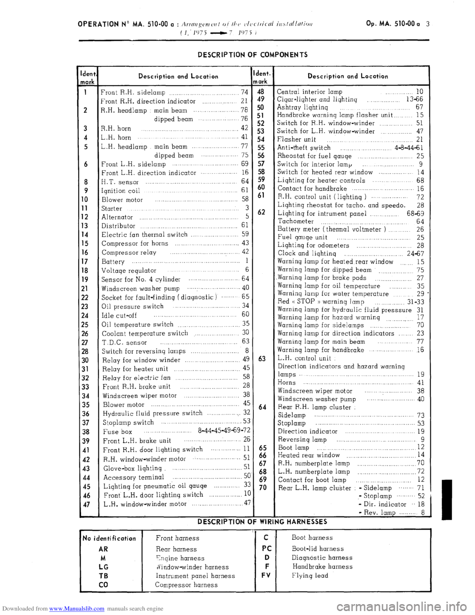
Downloaded from www.Manualslib.com manuals search engine OPERATION N” MA. 510-00 a : Arrnr~g(,v~ ('I, I 0 / Ih CJ c~lvclric-cil irtslnllc7liori Op. MA. 510-00 a 3
(I.‘1975 -7 1975 J
-
den{
lark
i
6
8
9
0
1
2
3
4
5
6
7
8
9
!l
!2
!3
!4
!5
!6
!7
!8
$0
)l
12
33
34
35
36
37
38
39
41
42
43
44
45
46
47
- DESCRIPTION OF COMPONENTS
Description and Location
‘ront R.H. sidelamp ................................... 74
‘rant R.H. direction indicator .................. 21
1.H. headlamp main beam ................. ..... 78
dipped beam ... .................. 76
3.H. horn 42 .............................................
,.H. horn ....................... ............. ............. 41
,.H. headlamp main beam .......................
77
dipped beam .................... 75
‘rant L.H. sidelamp .........
........................
69
:ront L.H. direction indicator .................. 16
I.T. sensor ............................................ 64
qnition coil ..............................................
61
3lower
motor .........................................
58
;tarter ...................................................... 3
Alternator ..................................................... 5
Xstributor 61 ...................................................
7lectric fan thermal switch .........................
59
Zompressor for horns ................................. 43
Compressor relay ..... .................
.............. 42
3attery ........... ...............................................
1
Joltaqe regulator ....................... ............. 6
jacket for fault-finding ( diagnosfic) ....... 65
3il pressure switch .... ....................... ... 34
:dle cut-off ........................................... 60
3il temperature switch
35 .............................
Coolant temperature switch ....................... 30
T.D.C. sensor ......................................... 63
Switch for reversing lamps .......................... 8
Relay for window winder ............................. 49
Relay for heater unit 45
................... ..............
Relay for electric fan 58 ..................................
Front R.H. brake unit 28 ...............................
Windscreen wiper motor .............................. 38
Blower motor ................................................ 45
Hydraulic fluid pressure switch ................... 32
Stoplamp switch ........................................... 53
Fuse box ..... .................... 8-44-45-49-69-72
Front L.H. brake unit ........................... ... 26
Front R.H. door lighting switch ... ............
11
R.H. window-winder motor .......................... 51
Glove-box lighting ....................................... 51
Accessory terminal ......................................
5c
Lighting for pneumatic oil gauge .............. 3:
Front L.H. door lighting switch
.................. I[ L.H .
window-winder motor ........................... .47 DESCRIPTION C
No identification
AR
M
LG
TB
co
Front harness
Rear harness
Ynqine harness
dindow-winder harness
Instrument panel harness
Compressor harness jent.
/ark
4”9 50
51
52
53
54
55
56
57
58
59
60
61
62
63
64
iz
67
68
69
70 Description and Location Central interior lamp ............ 10
Cigar-liqhter and lighting
.............. 13-66
Ashtray liqhtinq ...................................
67
Handbrake warning lamp flasher unit
........ 15
Switch for R.H. window-winder
.............. 51
Switch for L.H. window-winder ................ 47
Flasher unit .............................................. 21
Anti-theft switch ......................... 4-8-44-61
Rheostat for fuel qauqe ............................ 25
Switch for interior lamp ... ....................
9
Switch for heated rear window ...................
14
Liqhting for heater controls ..................... 68
Contact for handbrake
............................... 115
R.H. control unit ( liqhtinq )
................... 72
Lighting rheostat for tacho. and speedo.
28
Lighting for intrument panel ................ 68-69
Tachometer
............................................ 64
Battery meter (thermal voltmeter )
.......... 26
Fuel gauge unit
..... ....... ....... ................ 25
Lighting for odometers
....... ......... .......... 28
Clock and lighting ................................ 24-67
Warning lamp for heated rear window
15 .......
Warning lamp for dipped beam 75
_, .................
Warninq lamp for brake pads ................... 27
Warninq lamp for oil temperature
............ 35
Warning lamp for water temperature
.......... 29
Red u STOP 1) warninq lamp
............... 31-33
Warninq lamp for hydraulic fluid presssure 31
Warninq lamp for hazard warning
17
...............
Warninq lamp for sidelamps .................... 70
Warning lamp for direction indicators ...... 23
Warninq lamp for main beam ................. 77
Warning lamp for handbrake
..................... 16
L.H. control unit
Direction indicators and hazard warning lamps .........................................................
19
Horns .......................................................... 41
Windscreen wiper motor ....... .................. 38
Windscreen washer pump .......................... 40
Rear R.H. lamp cluster
Sidelamp ...................................................
73
Stoplamp ....................... .............................. 53
Direction indicator ......................................
19
Reversing lamp ....................... .............
9
Boot lamp ................................................... I2
Heated rear window 14 .....................................
R.H. numberplate lamp ...............................
70
L.H. numberplate lamp ...........
.................... 72
Contact for boot lamp .............................
12
Rear L.H. lamp cluster - Sidelamp
........ 71
,- Stoplamp
.......... 52
- Dir. indicator .. 18
- Rev. lamp ......... 8
IG HARNESSES
Boot harness
Boot-lid harness
Diagnostic harness
Handbrake harness
Flying lead
Page 308 of 394
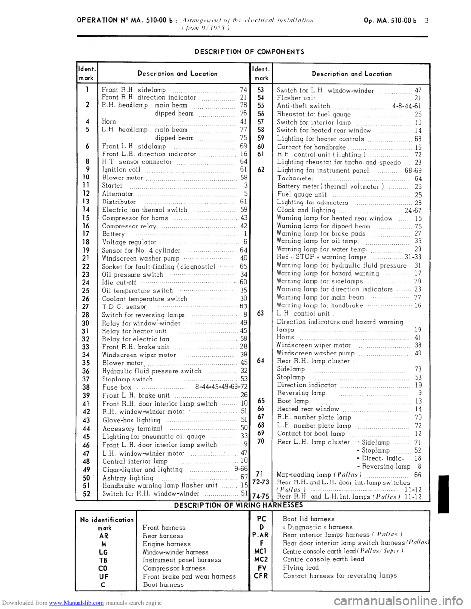
Downloaded from www.Manualslib.com manuals search engine DESCRIPTION OF COMPONENTS
dent.
Ident.
Description ond Location
n ark Description and Location
mark
1
Front R.H sidelamp
74 53
Switch for L.H. window-winder .,, 47
Front R H direction indicator
21 54 Flasher unit
.... 21
2 R.H. headlamp
main beam
78 55 Anti-theft switch
4-a-44-61
dipped beam
76 56 Rheostat for fuel gauqe
,.. 25
4 Horn
41 57
. Switch for interior lamp .,. 10
5 L.H headlamp main beam
.., .., ,.. 77 58
Switch for heated rear window
14
dipped beam”: 75 59 Lighting for heater controls _.. 68
6 Front L H sidelamp
.,. 69 60
Contact for handbrake .._....
16
Front L.H. direction indicator ,.... ._. _._.. 16 61
8 R.H control unit (lighting )
72
H T
sensor connector ,. 64
Lighting rheostat for tacho and speed0
28
9
Ignition coil ,.,
61 62 Lighting for instrument panel 68-69
10
Blower motor 58
Tachometer
.,.
64 11
Starter 3 Battery meter ( thermal voltmeter ) 26 12 Alternator ..I
5
Fuel gauqe unit 25 13
Distributor
61 14 Lighting for odometers _. 28 Electric fan thermal switch 59
Clock and lighting .._.. .,. 24-67
15
Compressor for horns 43 Warning lamp for heated rear window
15 16 Compressor relay 42 Warning lamp for dipped beam
_.. 75 17
Battery 1 Warninq lamp for brake pads 27 18 Voltage regulator . . . . . . . . . . 6 Warning lamp for oil temp. ,,_.. 35
19
Sensor for No 4 cylinder
64 Warning lamp for water temp. ..._.,,, ,,,,. 29 21
Windscreen washer pump ... .. ......
40 Red (( STOP )) warning lamps
31-33 22
Socket for fault-finding (diagnostic) .‘.‘.... 65 Warninq lamp for hydraulic fluid pressure
31 23
Oil pressure switch 34 Warning lamp for hazard warning
17 24 Idle cut-off .._........ 60
Warning lamp for sidelamps
70 25
Oil temperature switch 35 Warning lamp for direction indicators 23 26
Coolant temperature switch 30 Warninq lamp for main beam .‘..... 77 27 ‘I’D f-, SenSOr 63
Warning lamp for handbrake ... .‘........-.. 16 28
Switch for reversinq lamps ... ... ....... 8 63 L H control unit 30
Relay for window -winder ... ... .‘........ 49 Direction indicators and hazard warning 31
Relay for heater unit 45 lamps .,. .,...._ .,. .._ 19
.,. .._.......... 32
Relay for electric fan 58 Horns 41 33
Front R H. brake unit
.._.. 28 Windscreen wiper motor
..,.... 38 34
Windscreen wiper motor
_.............. 38 Windscreen washer pump
.._...... 40 35
Blower motor, ,._..._._....._._..._........ 45 64 Rear R.H. lamp cluster 36
Hydraulic fluid pressure switch _..._......... 32 Sidelamp .._...... 73
37
Stoplamp switch 53 S toplamp
_. _. _. _. _. _. _. 53
.._..............
38
Fuse box 8-44-45-49-69-72 Direction indicator
19
_.. _._.. 39
Front L.H. brake unit
. .._.._............... 26 Reversing lamp 9 41
Front R.H. door interior lamp switch 10
6665 Boot lamp .._. ._. 13
42
R.H. window-winder motor ..- 51 Heated rear window
14 43
Glove&or lightinq .._............ 51 67 R.H. number plate lamp 70
44
Accessory terminal 50 68 _..,......... L.H. number plate lamp
72 45
Lighting for pneumatic oil qauge 33 h9 Contact for boot lamp .._.. .._. .._........ 12 46
Front L.H. door interior lamp switch 9 70 Rear L.H. lamp cluster
- Sidelamp
71 47
L.H. window-winder motor ..: 47 - Stoplamp .._._... 52
48
Central interior lamp
10 - Direct. indic. 18 49
Cigar-lighter and lighting 9-66 - Reversing lamp 8
.._....
50 Ashtray lighting 67 71 Map-reading lamp f Pnl/ns ) .._..._....._.
66
_._......._...................... 51
Handbrake warning lamp flasher unit .._._.._ 15 72-73 Rear R.H. and L.H. door int. lamp switches 52
Switch for R.H. window-winder _..._.. 51 (P(/llgs ) 1 l-12 74-75 Rear R.H. and L.H. int. lamps ( f’nlins ) 1 l-12 DESCRIPTION OF WIRING HARNESSES
No identification PC
Boot lid harness mark
Front harness D <( Diagnostic )) harness AR
Rear harness P.AR Rear interior lamps.harness f I’n//nc )
M Engine harness F
Rear door interior lamp switch harness (Pflj/~.s LG
Window-winder harness MC1 Centre console earth lead( Pall~.~,’ S~/jczr ) TB
Instrument panel harness MC2 Centre console earth lead
co Compressor harness Flying lead UF
Front brake pad wear harness C: Contact harness for reversing lamps
C Boot harness
Page 316 of 394
Downloaded from www.Manualslib.com manuals search engine OPERATION No MA. 510-00 b : i
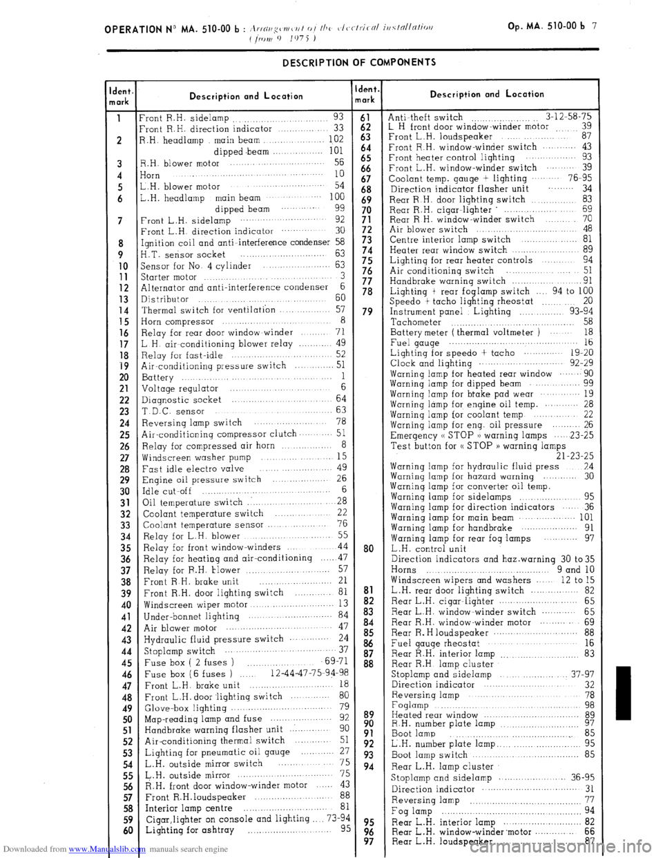
.,.~//,q~~r~/~/// o/ //IV ~,lc,ctrit 01 iti.sfnl/nlio,l Op. MA. 510-00 b 7
I /IONI 9
1075 )
dent,
lark
1
2
7
8
9
10
11
12
13
14
15
16
17
18
19
20
21
22
23
24
25
26
27
28
29
30
31
32
33
34
35
36
37
38
39
40
41
42
43
44
45
46
47
48
49
50
51
52
53
54
55
56
57
58
59
60 DESCRIPTION OF COMPONENTS
Description and Location
‘rant R.H. sidelamp 93 .........................
‘rant R.H. direction indicator .............
33
3 .H. headlamp main beam ............... 102
dipped .beam ............... 101
3.H. blower motor .......... ........ ...... 56
iorn ....... ...... ....
........................... 10
,,H, blower motor ...........................
54
,.H. headlamp main beam .................. 100
dipped beam ........... 99
‘rant L.H. sidelamp ........................
92
Front L.H. direction indicator ................ 30
[gnition coil and anti-interference condenser 58
‘I.T. sensor socket .............................
63
jensor for No. 4 cylinder ................
63
5tarter motor .......................... 3
41ternator and anti-interference condenser 6
Distributor ...... ......................
60
Thermal switch for ventilation ............ 57
Horn compressor ................................ 8
Relay for rear door window winder ....... 71
L H. air conditioning blower relay ............
49
Relay for fast-idle ........................... 52
Air-conditioning pressure switch ............ 51
Battery ...............................
1
Voltage regulator ..................... 6
Diagnostic socket ...................... 64
T.D.C. sensor .......................... 63
Reversing lamp switch ......................
78
Air-conditioning compressor clutch.. ........
51
Relay for compressed air horn ............... 8
Windscreen washer pump ......... ........ 15
Fast idle electro valve ......................
49
Engine oil pressure switch ............... 26
Idle cut-off ...................................
6
Oil temperature switch .: ....................
28
Coolant temperature switch ............
22
Coolant temperature sensor ...............
76
Relay for L.H. blower ....................... 55
Relay for front window-winders ............
44
Relay for heating and air-conditioning
.... ..4 7
Relay for F.H. tlower ........................
57
Front R H. brake unit .........................
21
Front R.H. door lighting switch ............ 81
Windscreen wiper motor ...........................
13
Under-bonnet lighting. ..................... ..... 84
Air blower motor ...................................... 47
Hydraulic fluid pressure switch ............ 24
Stoplamp switch ..................................
37
Fuse box ( 2 fuses ) ......................
69-71
Fuse box (6 fuses ) ..... 12-44-47-75-94-98
Front L.H. brake unit ............................
18
Front L.H. door ‘lighting switch .............
80
Glove-box lighting ................................. 79
Map-reading lamp and fuse .....................
92
Handbrake warning flasher unit ..............
90
Air-conditioning thermal switch .......... 51
Lighting for pneumatic oil gauge ............
27
L.H. outside mirror switch ................
75
&.H. outside mirror ................................. 75
R.H. front door window-winder motor ...... 43
Front R.H.loudspeaker ....................... 88
Interior lamp centre .............................. 81
Cigar,lighter on console and lighting .... 73-94
Lighting for ashtray .............................. 95 dent.
lark
2
63
b:
66
67
68
69
3:
5;
5:
76
77
78
79
80
to9
8:
93
94
95
99s Description and Location
Anti-theft switch
.._.. _..,..... _. 3-12-58-75
L H front door window-winder motor i;
Front L.H. loudspeaker
Front R.H. window-winder switch ....... .... 43
Front heater control lighting ..............
93
Front L.H. window-winder switch
........ 39
Coolant temp. gauge + lighting
........ 76-95
Direction indicator flasher unit ......... 34
Rear R.H. door lighting switch
................ 83
Rear R.H. cigar-lighter ’ ...................
69
Rear R H. window-winder switch
........ 70
Air blower switch ...............................
48
Centre interior lamp switch
.................. 81
Heater rear window switch
...................... 89
Lighting for rear heater controls
....... 94
Air conditioning switch
................
51
Handbrake warning switch
....................
91
Light.ing t rear foglamp switch
.... 94 to 100
Speed0 t tacho lighting rheostat
....... 20
Instrument panel
Lighting .............. 93-94
Tachometer
........................................ 58
Battery meter ( thermal voltmeter )
.....
18
Fuel gauge .., ................... ...................... 16
Lighting for speed0 + tacho
............. 19-20
Clock and lighting ........... ...............
92-29
Warning lamp for heated rear window
...... 90
Warning lamp for dipped beam
............. 99
Warning lamp for bt-ake pad wear
.......... 19
Warning lamp for engine oil temp. .......... 28
Warning lamp for coolant temp
..........
22
Warning lamp for eng. oil pressure ......... 26
Emergency (( STOP )) warning lamps
... ...23-2 5
Test button for (( STOP )) warning lamps
21-23-25
Warning lamp for hydraulic fluid press ..7.4
Warning lamp for hazard warning 30
Warnina lamu for converter oil temo.
Warnin; lamb for sidelamps
..... : ..........
95
Warning lamp for direction indicators
.... 36
Warning lamp for main beam
................. 101
Warning lamp for handbrake
....................
91
Warning lamp for rear fog lamps ........... 97
L.H. control unit
Direction indicators and haz.warning 30 to35
Horns ... ........................................
9 and 10
Windscreen wipers and washers
.... 12 to 15
L.H. rear door lighting switch
................
82
Rear L.H. cigar-lighter
............................ 65
Rear L.H. window-winder switch
............ 65
Rear R.H. window-winder motor
......... 69 Rear Re H loudspeaker
............................ 88
Fuel gauge rheostat ....................... .....
16
Rear R.H. interior lamp
......................
83
Rear R.H lamp cluster
Stoplamp and sidelamp
................ ... 37-97
Direction indicator .............................. 32
Reversing lamp ...................................
78
Foglamp .................................................
98
Heated rear window
.................................. 89
R.H. number plate lamp
97 ..........................
Boot lamp
.......................................
85
L.H. number plate lamp.. ..........................
95
Boot lamp switch
.............................. 85
Rear L.H. lamp cluster Stoplamp and sidelamp
....................... X6-95
Direction indicator ......................... ........
31
Reversing lamp
.......................
................
Fog lamp
.................................................. ii
Rear L.H. interior lamp ............................
Rear L.H. window-winder’motor
............. 68;
Rear L.H. loudspeaker ............................ 87
Page 324 of 394
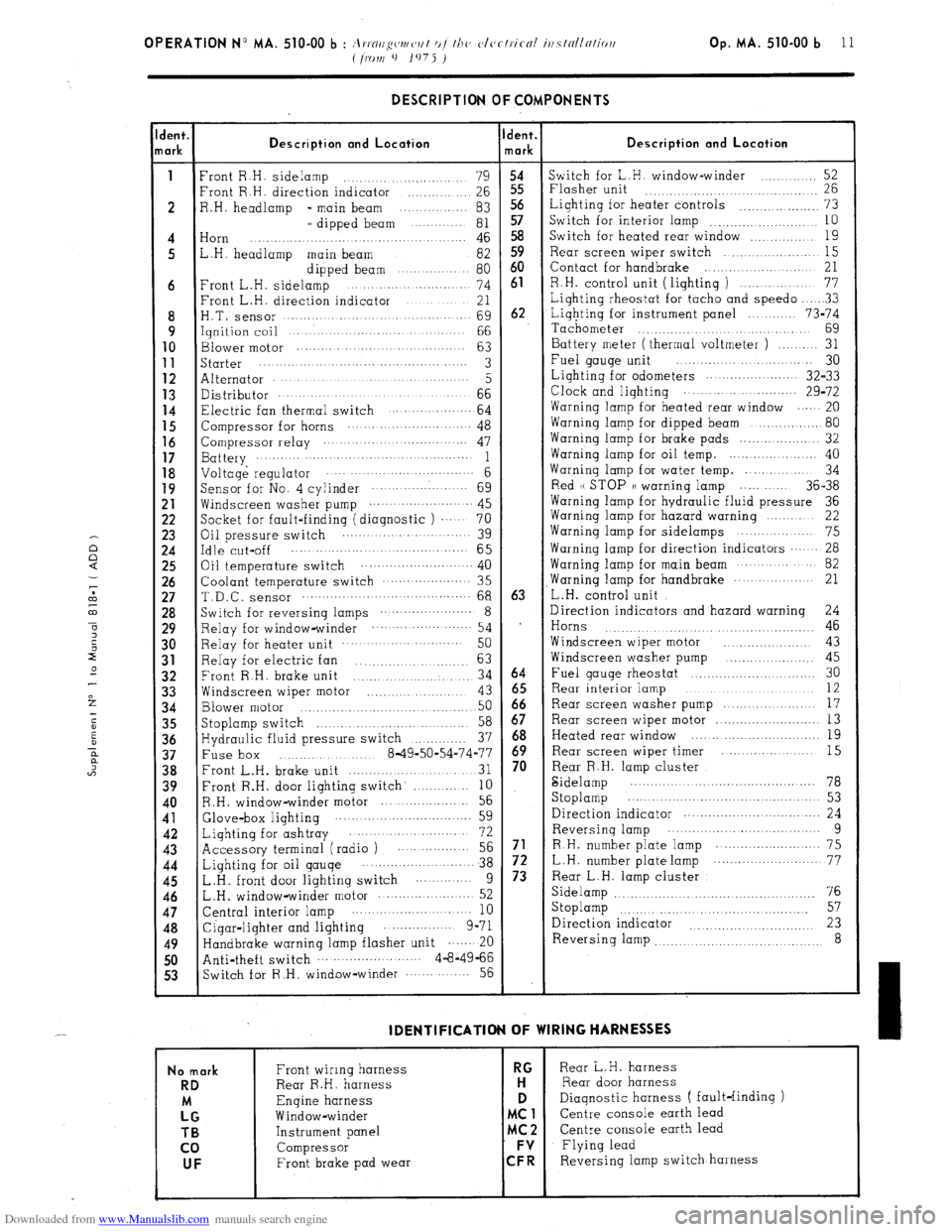
Downloaded from www.Manualslib.com manuals search engine Op. MA. 510-00 b 11 DESCRIPTION OF COMPONENTS
lent.
lark Description and Location Ident.
mark Description and Location
1
Front R.H. sidelamp
........................ 79
54 Switch for L.H. window-winder
..... ....... 52
Front R.H. direction indicator
.............. 26 55 Flasher unit
26 ....................................
2 R.H. headlamp - main beam ............... 83 Lighting for heater controls
................... 73
L dipped beam
........... 81 “5;
Switch for interior lamp
10 ..........................
4 Horn
.... 46 58 Switch for heated rear window
................ 19 ..................................
5 L.H. headlamp main beam
82 59 Rear screen wiper switch
.................... 15
Front L.H. sideli?pped..beam ... 80 60 Contact for handbrake
..................... 21
6 ............... ..
74 61 R.H. control unit ( lighting )
............... 77
Front L.H. direction indicator
............ 21 Lighting rheostat for tacho and speed0
.... ..3 3
8 H.T. Sensor .................................
69 62 Lighting for instrument panel
........ 73-74
9 Ignition coil
........................... 66
Tachometer .............................
69 10
Blower motor ...............
.................
63 Battery meter (thermal voltmeter )
........ 31 11 starter
...............................................
3 Fuel gauge unit ................ ..... ...... 30
12 Alternator ............................................
5 Lighting for odometers
...................... 32-33 13 Distributor
.... ......... .......... ..........................................
66 Clock and lighting
29-72 14
Electric fan thermal switch 64 Warning lamp for heated rear window ......
................. 20
15
Compressor for horns ........................... 48 Warning lamp for dipped beam
................. 80 16
Compressor relay .............................. 47 Warning lamp for brake pads
................... 32 1’;
Battery ...........................................
1 Warning lamp for oil temp. ...................... 40
Voltage regulator .............................. 6 Warning lamp for water temp. ............. 34
19
Sensor for No. 4 cylinder ....................
69 Red (( STOP )) warning lamp ..... ..... 36-38
:: Windscreen washer pump ....... ................. 45
Warning lamp for hydraulic fluid pressure 36
Socket for fault-finding (diagnostic )
.... 70 Warning lamp for hazard warning
....... 22 23
Oil pressure switch ..........................
39 Warning lamp for sidelamps .......
.......... 75 :“5
Idle cut-off ....................................... 65 Warning lamp for direction indicators ...... 28
Oil temperature switch ..................... ... .. 40 Warning lamp for main beam
........... 82
:; Coolant temperature switch
.....................
35 ,Warning lamp for handbrake
............... 21
T.D.C. sensor .......................................... 68 63
L.H. control unit
28 Switch for reversing lamps ....................... 8
Direction indicators and hazard warning
24
29 Relay for window-winder ........................
54 1
Horns 46 .............. ............... ..........
30 Relay for heater unit
........................
50 Windscreen wiper motor
.. .............. 43
31
Relay for electric fan ................
63 Windscreen washer pump .................... 45
32
Front R.H. brake unit
.................... 34 64 Fuel gauge rheostat ..............................
30
33 Windscreen wiper motor ........................... 12
................ 43 65 Rear interior iamp
34 Blower motor 50 66
Rear screen washer pump ...................
17
................... ................. 35
Stoplamp switch
58 67 Rear screen wiper motor
.......................... 13
..........................
36 Hydraulic fluid pressure switch
37 68 Heated rear window ...............................
19
..............
;‘8 Fuse box 8-49-50-54-74-77 ;; Rear screen wiper timer ....................
15
............. .........
Front L.H. brake unit
............................... 31 Rear R.H. lamp cluster
39 Front R.H. door lighting switch’
............ 10 Sidelamp
.......................................... 78
10 R.H. window-winder motor
................... 56 Stoplamp ..............................................
53 11
Glove-box lighting 59 Direction indicator ..................................
24 ...... ...........................
42
Lighting for ashtray 72 Reversing lamp ... ........... ............ .......
9 .....................
43 Accessory terminal (radio ) .................. 56 71
R.H. number plate lamp .......................... 75
44
Lighting for oil gauge ........................ 38 72 L.H. number plate lamp ............... ... ....... 77
45
L.H. front door lighting switch
...........
9 73 Rear L.H. lamp cluster
46 L.H. window-winder motor
76 ..................... 52 Sidelamp
.............................................
47 Central interior lamp 57
..........................
10 Stoplamp
..........................................
48
Cigar-lighter and lighting ...............
9-71 Direction indicator 23 .........................
49 Handbrake warning lamp flasher unit ....... 20 Reversing lamp
8 ................................
50 Anti-theft switch
.......................... 4-8-4966
53 Switch for R.H, window-winder
............ 56 IDENTlFlCATlON OF WIRING HARNESSES
No mark
RD
LMG TB
co UF
Front wiring harness RG Rear L.H. harness
Rear R.H. harness H Rear door harness
Engine harness D
Diagnostic harness ( fault-finding )
Window-winder MC1
Centre console earth lead
Instrument panel MC2 Centre console earth lead
Compressor FV
Flying lead
Front brake pad wear CFR Reversing iamp switch harness