c matic Citroen CX 1977 1.G Owner's Manual
[x] Cancel search | Manufacturer: CITROEN, Model Year: 1977, Model line: CX, Model: Citroen CX 1977 1.GPages: 394
Page 359 of 394

Downloaded from www.Manualslib.com manuals search engine OPERATION No MA. 560.0 : ~hrrkin~ o,,d oc/@s/i,,g I/><, wiurisrrrr,, wip’r. Op. MA. 560.0
1
Fi
m
0 CHECKING AND ADJUSTING THE WINDSCREEN WIPER.
FRONT WINDSCREEN WIPER MOTOR
CHARACTERISTICS.
Manufacturer DUCELLIER
Reference No. 4966 A
Field coils Ferrite
Armature : Endfloot (adjustable by means of stop-screw) : 0.2 mm
Nominal dia. of commutator :
24 mm
Min. dia. after machining : 23 mm
Brushes : Ref. No. :
CL 7239
Minimum length after wear : 5.5 mm
Ratio : .._...................................................................................................
44 1
Connection and circuit diagram as in Op. MA. 510 00.
ELECTRICAL CHECK. BOSCH
0390 346 127
Ferrite
0
23.2 mm
23 mm
1.394.320-058 059, 062
7.5 mm
49 1
1. First speed :
Nominal power : IO watts
Speed, under no load, at 13.5 volts = 50 rpm Corresponding current = I.8 A
Torque, motor locked, at 13.5 volts = 1.9 da Nm 7 13.74 ft.lb min. Corresponding current 18 A max.
Torque at 40 rpm and 13.5 volts = 0.2 do Nm (1.45 ft.lb) Correspondinq current = 5.5 A max.
- Torque ot 20 rpm and 13.5 volts = 1.07 da Nm (7.74 ft.lb) min Corresponding current = 13.2 A max.
2. Second speed :
Nominal power : 15 watts
Speed under no load at 13.5 volts = 70 rpm Corresponding current = 2.3 A
Torque motor locked at 13.5 volts = 1.5 do Nm (IO.85 ft.lb) min Corresponding current = 21 A max
Torque at 60 rpm and 13.5 volts = 0.2 da Nm (1.45 ft.lb) min Corresponding current = 7 A max
Torque ot 30 rpm and 13.5 volts = 0.9 da Nm (6.51 ft.lb) min Corresponding current = 14.7 A mrx.
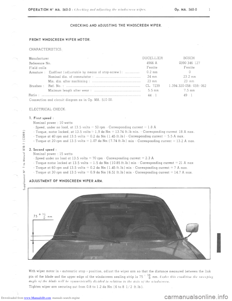
ADJUSTMENT OF WINDSCREEN WIPER ARM
With wiper motor in (< automatic stop )/ position, adjust the wiper arm so that the distance measured between the link
pin of the blade and the upper edge of the windscreen sealing strip is 75 ‘t
mm. L’vd‘ar /his rondiliw, /he 51, rvp;,,g
m,g/r 0, /he bladr ,,~i// hv symv,r~/rirn//v dil idrd it, w/n/io,, 10 /he O.YiS “, I/w r,‘iri
Tighten wiper arm securing out from 0.8 to 1.2 da Nm (6 to 8 l/2 ft.lb).
Page 364 of 394

Downloaded from www.Manualslib.com manuals search engine IV. DISTRIBUTION FLAP ( Vl) CONTROL
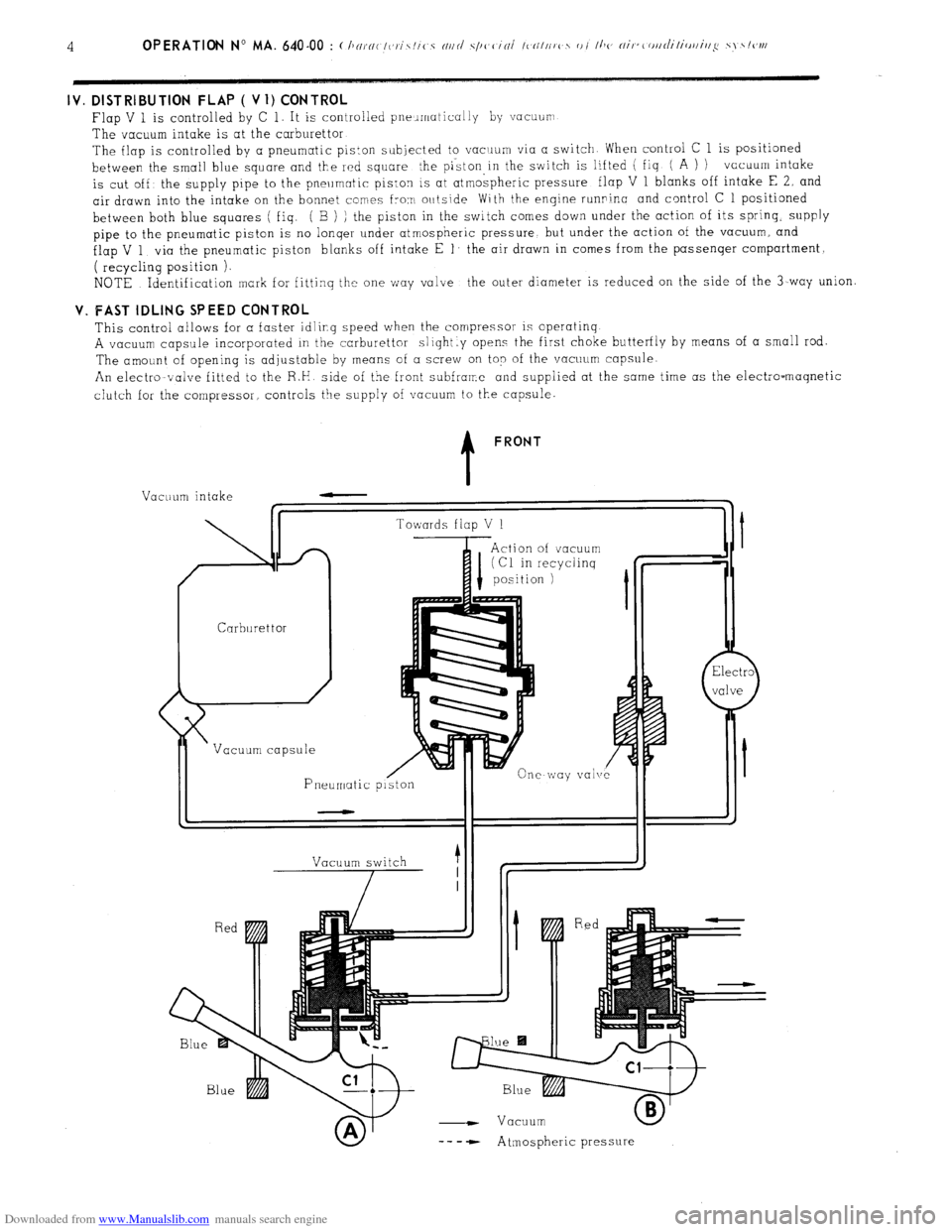
Flap V 1 is controlled by C 1. It is controlled pneumatically by vacuurr
The vacuum intake is at the carburettor
The flap is controlled by a pneumatic piston subjected to vacrrum via a switch When control C 1 is positioned
between the small blue square and the red square the piston,in the switch is lifted ( fiq ( A ) ) vacuum intake
is cut off’ the supply pipe to the pneumatic piston is at atmospheric pressure flap V 1 blanks off intake E 2, and
air drawn into the intake on the bonnet comes from outside With the engine runninc and control C 1 positioned
between both blue squares ( fiq. ( B ) ) the piston in the switch comes down under the action of its spring.
supply
pipe to the pneumatic piston is no lonqer under atmospheric pressure but under the action of the vacuum, and
flap V 1 via the pneumatic piston blanks off intake E 1’ the air drawn in comes from the passenqer compartment,
( recycling position ).
NOTE Identification mark for fittinq the one way valve the outer diameter is reduced on the side of the 3-way union V. FAST IDLING SPEED CONTROL
This control allows for a faster idling speed when the compressor is operatinq
A vacuum capsule incorporated in the carburettor slightly opens the first choke butterfly by means of a small rod.
The amount of opening is adjustable by means of a screw on top of the vacuum capsule.
An electromvalve fitted to the R.H side of the front subframe and supplied at the same time as the electro-maqnetic
clutch for the compressor controls the supply of vacuum to the capsule. t FRONT
Vacuum intake
Carburettor /
Vacuum capsule
Pneumatic p Towards flap V 1
Action of vacuum
I (Cl in recyclinq
position 1
vale
Vacuum switch
7 1
- Vacuum
-- - - Atmospheric pressure
Page 365 of 394

Downloaded from www.Manualslib.com manuals search engine OPERATION No MA. 640-00 : (:hnrnc-/eris/ics nrtd s.pcc-in/ ~bntttrcs of I/T<< nir- Op. ihA. 640-00 5
c-ottdiliottittg systc~ttt
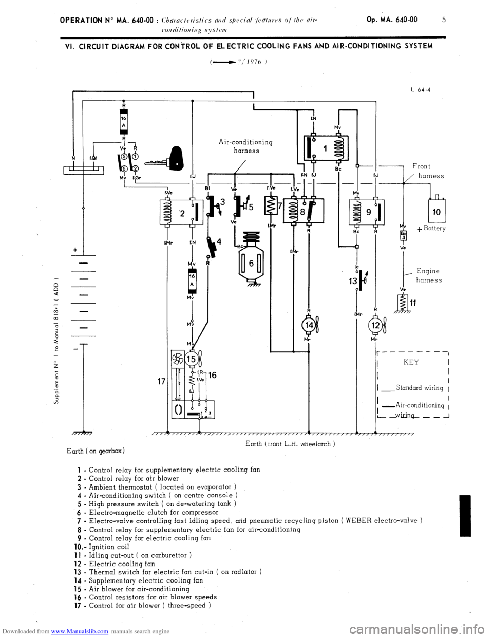
VI. ClRdUlT DIAGRAM FOR dONiROL OF ELECTRIC COOLING FANS AND AIR-CONDITIONING SYSTEM
(-'/lo76 )
I
I L 64-4
I 1. I
+I
-
Air-conditioning
harness
r
-I% ii.+
f:N
r
Mv
A
-1 Front
b 3
1
Engine
harness
VC -
I- __------
I KEY
I I
I
I- Standard wiring 1
17
/TTj I I
I -Air-conditioning 1
L2Ginq--~_J
Earth (front L.H. wheeiarch )
Earth on gearbox) 1
- Control relay for supplementary electric cooling fan
2 - Control relay for air blower
3 - Ambient thermostat ( located on evaporator )
4 - Air-conditioning switch ( on centre console )
5 - High pressure switch ( on de-watering tank )
6 - Electra-magnetic clutch for compressor
7 .
Electra-valve controlling fast idling speed, arid pneumatic recycling piston ( WEBER electro-valve )
8 - Control relay for supplementary electric fan for air-conditioning
9 - Control relay for electric cooling fan
lo.- Ignition coil 11
- Idling cut-out ( on carburettor ) 12
- Electric cooling fan 13
- Thermal switch for electric fan cut-in ( on radiator ) 14
- Supplementary electric cooling fan 15
- Air blower for air-conditioning 16
- Control resistors for air blower speeds 17
- Control for air blower ( three-speed )
Page 375 of 394

Downloaded from www.Manualslib.com manuals search engine 6
OPERATION No MA. 640-O : ( hvrsi~/p nsd ndj/w/isyc /I><, nirr~,s~l;/io,,i,,,~ syc,<,,,,
B. VEHICLES FITTED WITH A SANI(Y0 COMPRESSOR
NOTE Filling operations on CI vehicle fitted with a
and differ from the (< ASPERA-FRIGO 1) compressor only in as much as there are no screws for opening and closing
the valves.
The act of connecting a flexible pipe onto the intake valve (2) of the compressor automatically opens the valve. Checking the oil level on the cc SANKYO ~ncompressor
(11 After having made’swe, the compressor contains
no R. 12 under pressure, remove filler plug ( 1).
b) Slacken compressor belt
cj Disconnect the supply lead to the clutch, from the
wiring harness. and connect it to the battery<, + >)
terminal.
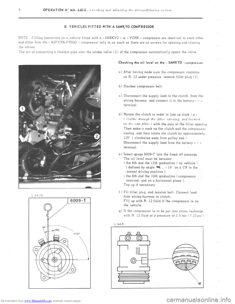
d) Rotate the clutch in order to line up mark ,< a ))
( visihlc~ tllrou~h Ihv /i/ler
opvui,,p. nad lorn/~~d
w I/TV rnw flnle ) with the axis of the filler opening.
Then make a mark on the clutch and the compressor
co-sing. and then rotate the clutch by opproximotely
110’ ( clockwise seen from pulley end ).
Disccninect the supply lead from the battery <( + )a
terminal.
e) Insert gouge 6009-T into the freed off passage
The oil level must be between
- the 8th and the 12th graduation ( on vehicle )
( defined by angle aC = 19. on a CX in the
normal driving position ).
- the 6th and the 10th graduation (compressor
removed. and on a horizontal plane ).
Top up if necessary.
f 1 Fit filler plug, and tension belt. Connect iead
from wiring hcrness to clutch.
Fill up with R. 12 fluid if the compressor is on
the vehicle.
g) If the compressor is to be put into store. rechange
with R. 12 fluid at o pressure of 0.5 bar (7.25psi)
L 64.9