Citroen CX 1977 1.G Manual Online
Manufacturer: CITROEN, Model Year: 1977, Model line: CX, Model: Citroen CX 1977 1.GPages: 394
Page 81 of 394
Downloaded from www.Manualslib.com manuals search engine OPERATION No MA. 142.00 : (.hornrt<,rislirs o,,d s,~“cinl ,<‘“,ur“s o! the Op. MA. 142.00 I(
rnrhrclfo,
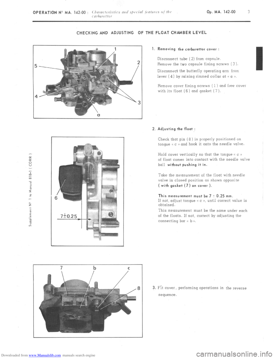
CHECKING AND ADJUSTING OF THE FLOAT CHAMBER LEVEL
7 b
1. Removing the carburettor cover :
Disconnect tube (2) from capsule.
Remove the two capsule fixing screws (3
1.
Discollnrci the butterfly operating arm from I
lever (4) by raising rimmed collar at
Rrmove COWI fixing screws ( 1) and free cover
with its float (6 ) and gasket (7 ).
2. Adjusting the float :
Check that pin (8 ) is properly positioned on
tongue e c N and hook it onto the needle valve.
Hold ccwe~ vertically so thot the tongue e( c P)
of float comes into contact with the needle valve
ball
without pushing it in.
Take the measurement of the float with needle
valve in closed position as shown opposite
( with gasket (7) on cover ).
This measurement must be 7 i 0.25 mm.
If not, adjust tongue e c K until correct value is
obtained.
This measurement must he the same under each
of the floats. If not, correct by adjusting the
connecting bar ss b )I.
3. Fit cover, performing operations in the reverse
sequence.
Page 82 of 394
Downloaded from www.Manualslib.com manuals search engine OPERATION No MA. 142-00 (I : Chnmrtcrisfirs rind special /<~a/rrrrs O/ the rnrhnrpftor Op. MA. 142-00 D 1
I
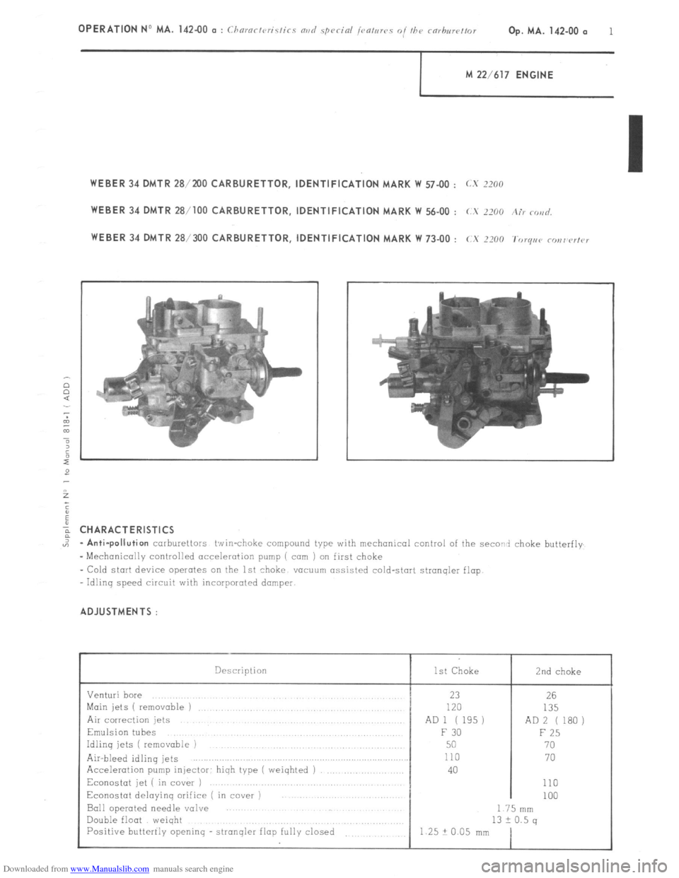
M 22/617 ENGINE
WEBER 34 DMTR 28/2UO CARBURETTOR, IDENTIFICATION MARK W 57-00 : LX IZOO
WEBER 34 DMTR 28/100 CARBURETTOR, IDENTIFICATION MARK W 56-00 : (.S 2200 Air c<,>id,
WEBER 34 DMTR 281300 CARBURETTOR, IDENTIFICATION MARK w 73-00 : cx 7x0 ‘f’orqac, COI,I’ClfCI
%
;
2
; CHARACTERISTICS
,: -Anti-pollution
carburettors twin-choke compound type with mechanical control of the sword choke butterfly
-Mechanically controlled acceleration pump ( corn ) on first choke
- Cold start device operates on the 1st choke vucuum assisted cold-start stranqler flop
ldlinq speed circuit with incarporoted dumper
ADJUSTMENTS :
Description
Venturi bore
Main jets ( removable 1
Air correction jets
Emulsion tubes
Idling jets ( removable )
Air-bleed idling jets
Acceleration pump injector: hiqh type ( weiqhted )
Econostat jet ( in cover )
Econostat deloyinq orifice ( in cover )
Ball operated needle valve
Double float weiqht
Positive butterily openinq - stronqler flop fully closed 1st Choke 2nd choke
23
120
AD 1 ( 195)
F 30
50
110
40 26
135
AD 2 ( 1.30)
F 25
70
70
110
100
I 75 nlm
13 2 0.5 q
1.25 + 0.05 mm
Page 83 of 394
Downloaded from www.Manualslib.com manuals search engine OPERATION No MA. 142 -00 b : ( hnrnr/vri.s/ir~ nvri .spc,cin/ /cn,,,rcs of /hc mrhrr//or Op. MA. 142.00 b 1
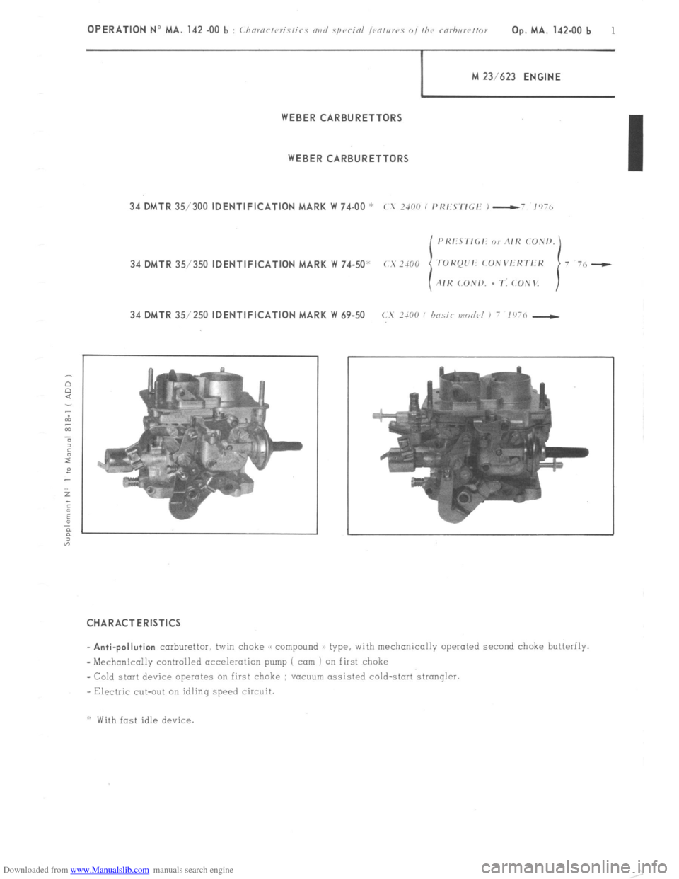
j I.4 23/623 ENGINE
WEBER CARBURETTORS
WEBERCARBURETTORS
34 DMTR 35/300 IDENTIFICATION MARK W 74-00 *
c I 2400 ( I’KIS’lIGf: 1 -- 1’176
34 DMTR 35/350 IDENTIFICATION MARK W 74-50’
34 DMTR 35/250 IDENTIFICATION MARK W 69-50 c. 1+00 / hocir modc~l , - ,‘I-6 -)
CHARACTERISTICS I
_ Anti-pollution
carburettor, twin choke GC compound )B type, with mechanically operated second choke butterily.
- Mechonicolly controlled acceleration pump ( cam 1 on first choke
- Cold start device operates on first choke ; VOCUU~ assisted cold-start stronqler.
_ Electric cut-out on idling speed circuit.
* With fast idle device
Page 84 of 394
Downloaded from www.Manualslib.com manuals search engine ADJUSTMENTS
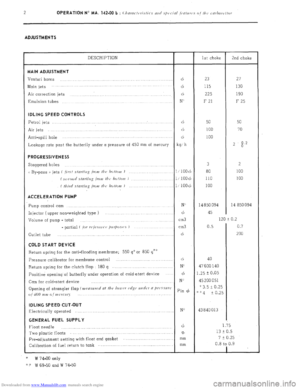
DESCRIPTION
1st choke
2nd choke MAIN ADJUSTMENT
Venturi bores
...................................................................................
d 23
27
Main jets ................. ...........................
... ................. ... ....... ...............
cl5 115 130
Air correction jets ..............................................................
d 225 190
Emulsion tubes
...............................................................
......
N’ F 21
F 25 IDLING SPEED CONTROLS
Petrol jets
.......................................................................................
d
50 50
Air jets .....................................................................................
(3
100 70
Anti-spill hole ............... ..............................................
....... ........
d 100
Leakage rate past the butterfly under a pressure of 450 mm of mercury
kg; h 2
$2 PROGRESSIVENESS
Staggered holes 3
2 ...............................................................................
u By-pass )) jets (
/irst stnrtiug /row the ho ttott/ J
100 ............................ 1 / 100 cb 80
( SC~COII~ slnrlirrg I.0Nf the bottom )
...................... l/ 1OOd 110 100
( third stnrfiug [row the bottov~ )
........................... l/100($
100 ACCELERATION PUMP
Pump control cam N”
14 850 094 14 850 094 ...............................................................................
Injector ( upper non-weighted type ) ............................................
d 45
Volume of pump - total
cm3 120 -t 0.2
.......................................................................
- partial ( /or r(‘/vre)~Co /~IIr/wS(‘S ) ................... ...........
cm3 0.5 0.7
Outlet tube
200 ................................................. ....... ...........
............... ... d COLD START DEVICE
Return spring for the anti-flooding membrane; 550 g” or 850 g*‘i;
Pressure calibrator for membrane control ...........................................
(1, 40
Return
spring for the clutch flap
180 g ...............................................
Ni 47 600 140
Positive opening’of butterfly under operation of coldstart device
.... d 1.25 2 0.05
Cam for cold-start device
N” 45 200 051
..............................................................
Opening of strangler flap (mensllrcd dt the loIc,cr c,dgc’ ur/dcJT 0 /lI’(‘.sSlI)‘C * 3.5 i 0.25
() j 4(j(J tr ,),, (J ,,, (Jr(-[,q Pin (b
““4 -t 0.25
..... ... .....................................................
... ...... IDLING SPEED CUT-OUT
Electrically operated NG 43840013 ............................................................................. GENERAL FUEL SUPPLY
Float needle
d 1.35
..................................................................................
Two plastic floats 13 F 0.5 ...................................
............... .............................
g.
7 t 0.25
Pre-adjustment setting with float and gasket ...............................
....... mm
Calibration of fuel return to tank .................................
......................... mm 0.8 to 0.9
1
*
W 74-00 only
* + W 69-50 and W 74-50 .
Page 85 of 394
Downloaded from www.Manualslib.com manuals search engine Op. MA. 142-00 SD 1 CX VEHICLES
ANTI- POLLUTION SYSTEM
FOR SWEDISH MARKET VEHIC LES
Page 86 of 394
Downloaded from www.Manualslib.com manuals search engine ALL CX VEHICLES
ANTI-POLLUTION SYSTEM ( SWEDISH MARKET )
I - cx 2200 :
The object of the system is to reduce the amount of unburnt hydrocarbons and the amount of CO in the exhaust
( 2 to 3 Z. of CO ) by injecting air under pressure into the exhaust manifold OPERATION :
As the engine rotates air pump ( 1 )supplies the air injectors (4) situated close to the exhaust valves: flap (3)
prevents the exhaust fumes from entering the air pump ( 1 ) and valve ( 2) assembly
There are two cases when it is necessary to stop the injection of air into the exhaust manifold. 1. During deceleration :
During fast decelerations. the mixture becomes richer combustion is incomplete, and the injection of air is
stopped in order 1.0 avoid a second combustion taking place in the exhaust system ( which would result in back
firinq ). During deceleration there is extreme low pressure downstream of the but!erfly ( 8 ). This in turn draws
in for a short period of time the diaphragm in valve (2 )
The air supplied by pump ( 1 ) is released into the atmosphere the calibrated hole u a )) on the diaphraqm
balances the pressure on either side of it, and the diaphragm returns to its initial position, allowinq air to
be once more injected into the exhaust manifold. 2. With the choke out :
With the choke in this position, the quantities of unburned hydrocarbons and CO are very considerable. It is
therefore necessary to stop the injection of air into the exhaust manifold so as to avoid an excessive
increase of temperature in the manifold. With the choke out, lever ( 5 ) connects relay ( 7 ) to earth.
The u WEBER )) electric contact is enerqized The air pressure at the outlet of air pump ( 1 ) increases the
effect of the low pressure on the diaphragm in valve (2 ) ( the air-pressure is felt above the diaphragm and
the low pressure produced by the carburettor (8) is felt below the diaphraqm ) the sliding valve in valve
unit ( 2 ) changes position, and the air is expelled into the atmosphere
If choke ( 5) is pushed back in, air is once again injected into the exhaust manifold.
Page 87 of 394
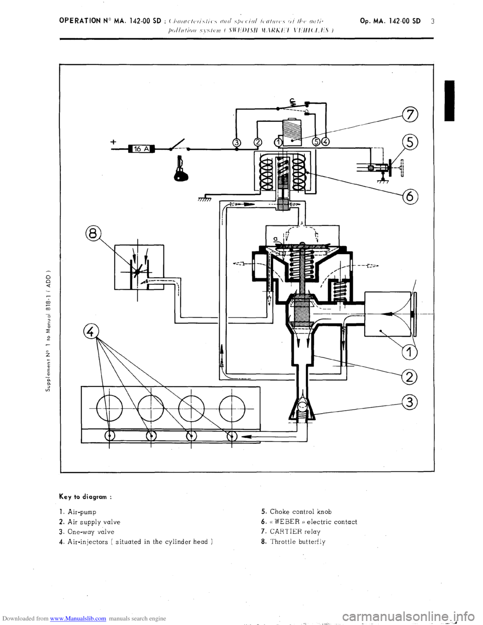
Downloaded from www.Manualslib.com manuals search engine Key to diagram :
1.
Air-pump 5. Choke control knob
2. Air supply valve 6. (( WEBER )) electric contact
3. One-way valve 7. CARTIER relay
4. Air-injectors ( situated in the cylinder head ) 8. Throttle butterfly
Page 88 of 394
Downloaded from www.Manualslib.com manuals search engine II. cx 2000
The object of the system is t3 reduce the amount of unburnt hydrocarbons and the amount of CO in the exhaust
( approximately 2 to 3
of CO ) by injectinq air under pressure into the exhaust manifold
OPERATION :
As the enqine rotates air pump ( 12) supplies the air injectors located near the exhaust valves: flap ( 13 )
prevents the exhaust fumes from entering the air pump and air supply duct assembly.
There are two cases where it is necessary to stop the injection of air into the exhaust manifold.
1. During deceleration :
Durinq fast deceleration. the mixture becomes richer combustion is incomplete and the injection of air is
stopped in order to avoid a second combustion takinq
place in the exhaust system ( which would result in
back-firinq ) Durinq deceleration there is extreme low pressure downstream of the butterfly ( 1 ). This in
turn draws in for a short period of time the diaphragm in valve ( 11 )
The air supplied by pump ( 12 ) is released into the atmosphere, the calibrated hole (( a 1) on the diaphragm
balances the pressure on either side of it and the diaphraqm returns to its initial position, allowinq air to
be once more injected into the exhaust manifold
2. With the choke out, for an engine coolant temperature of above 45’ + 3’ C, and whenever the coolant tempe-
rature remains above 35’ i “,I C.
In this situation the quantities of unburnt hydrocarbons and CO are very considerable It ‘is therefore necessary
to stop the injection of air into the exhaust manifold so as to avoid any excessive increase of temperature in
the manifold. On CX 2000 vehicles, injkction of air will be stopped when the enqine water temperature reaches
45” + 3- C Thermal switch ( 8 ) opens, relay ( 9 )
1s no lonqer enerqized. but electro-valve ( 7 ) remains live
( relay lead ). and is earthed via the choke control
The air pressure at the outlet of air-pump ( 12 )
increases the effect of the low pressure on the diaphraqm in
valve ( 11 ) ( the air pressure is felt above the diaphraq,m, and the low pressure produced by the carburettor (2)
is felt below the diaphraqm ). the slidinq valve in the duct chanqes position and the air is expelled into the
atmogphere If the choke ( 10) is pushed back in air is once again injected into the exhaust manifold
DEVICE FOR OPENING THE BUTTERFLY :
The object of the device is to maintain combustion during sudden deceleration up to an enqine speed
of
Nd 7 1800 + 100 rpm.
Durinq deceleration for any enqine speed above Nd, the electronic tachometer housinq ( 6 ) earths the
windinq of relay ( 5) Therefore the H PIERBURG 1) electro-valve ( 4) is no lonqer enerqized. Electro-
valve ( 4) is then under low-pressure, below the diaphragm of the device ( 3 ) for opening the butterfly
When the decreasinq enqine speed falls below
Nd, the electronic tachometer housing (6 ) cuts out the
earth of the winding in relay ( 5) Therefore the (( PIERBURG )) electro-valve ( 4) is enerqized The
electro-valve is no lonqer under low pressure below the diaphraqm of the device (3) for openinq the
butterfly the throttle butterfly returns to it s stop aqainst the idlinq speed adjustment screw. The dia-
phraqm of the device (3) for openinq the butterfly will once aqain be affected by low pressure ( under
the control of the electronic tachometer housing ) once the increasing engine speed reaches
NC ~ Nd t 50 to 250 rpm
Page 89 of 394
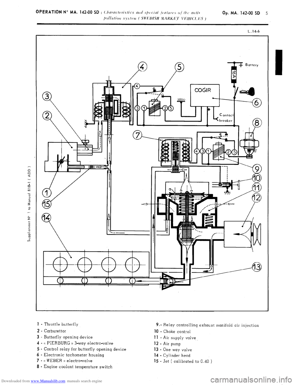
Downloaded from www.Manualslib.com manuals search engine 1 - Throttle butterfly
2 - Carburettor
3 - Butterfly openinq device 4-
N PIERBURG 1) 3-way electro-valve
5 - Control relay for butterfly opening device
6 - Electronic tachometer housing 7-
(( WEBER H electro-valve 8
- Engine coolant temperature switch 9.” Relay controlling exhaust manifold air injection 10
- Choke control
11 - Air supply valve 12
- Air pump 13 -
One way valve
14 - Cylinder head
15 - Jet ( calibrated to 0.40 )
Page 90 of 394
Downloaded from www.Manualslib.com manuals search engine OPERATION No MA. 142-O : Adj,,s/iaji f/a<, rarhnrt,//or Op. MA. 142.0
1
ADJUSTING THE IDLING SPEED
To carry out this adjustment, the following is needed
A tachometer
A device lor checkinq idling speed adjustments on the carburettor ( or on approved gas analyser )
- A CDA 23 checking oppmotus or a workshop test bench ( equipment mentioned in the Equipment and Repair
Materials list, or in the Tools and Equipment notes green notes )
NOTE : WEBER Carburettors ref. No W 54-50, 55-50, 69-50, 74-50 fitted on 1977 models onwards ore fitted with a
fool-proof plug ( white ) on the mixture screw. To adjust the exhaust emission, this plug has to be
removed, and
replaced, after adjustment, with a a Repair PI plug ( black ). See Op. MA, 142-000 for removing and fitting the plug,
and the necessary tools.
ADJUSTMENT CONDITIONS
1.
The idling speed adjus!ment must be carried out on an engine on which the rocker clearances and the ignition
are correctly set. with a clean air filter and
with the engine in good order.
2. Check that the butterflies return fully to their stops.
3. 30 not let pnythinq except the ignition and the engine cooling fan ( or ions ) impose any load on the alternator.
4. Run the engine to bring the
oil temperature up to 70 to 80’ C ( wait for the electric cooling fan ( or fans 1 to cut
in 1.
I. M 20/616, M 22/617, M 23/623 ENGINES I i< ?I< (5 wi/hr ,111 /or<,,,< co,1, <,r,cr or air ro,,di/io,ii?,g I ,I ‘-/
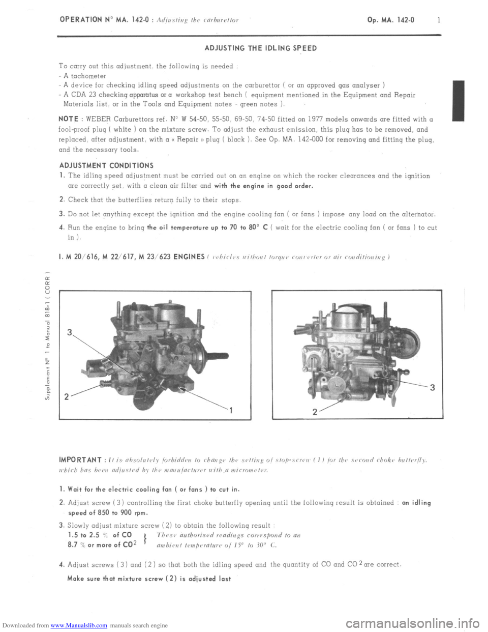
1. Wait for the electric cooling fan ( or fans ) to cut in.
2. Adjust screw (3) controlling the first choke butterfly opening until the following result is obtained : an idling
speed of 850 to 900 rpm.
3. Slowly adjust mixture screw ( 2) to obtain the following result
1.5 to 2.5 “/ of CO
1 7h~se authoris<,
8.7
% or more of CO2 nmbiot~l I~mpcuatur~ 0i 1 Y to 30” C.
4. Adjust screws (3 ) and (2 ) so that both the idling speed and the quantity of CO and CO 2 me correct.
Make sure that mixture screw (2) is adjusted last