lock Citroen CX 1978 1.G Owner's Manual
[x] Cancel search | Manufacturer: CITROEN, Model Year: 1978, Model line: CX, Model: Citroen CX 1978 1.GPages: 394
Page 195 of 394
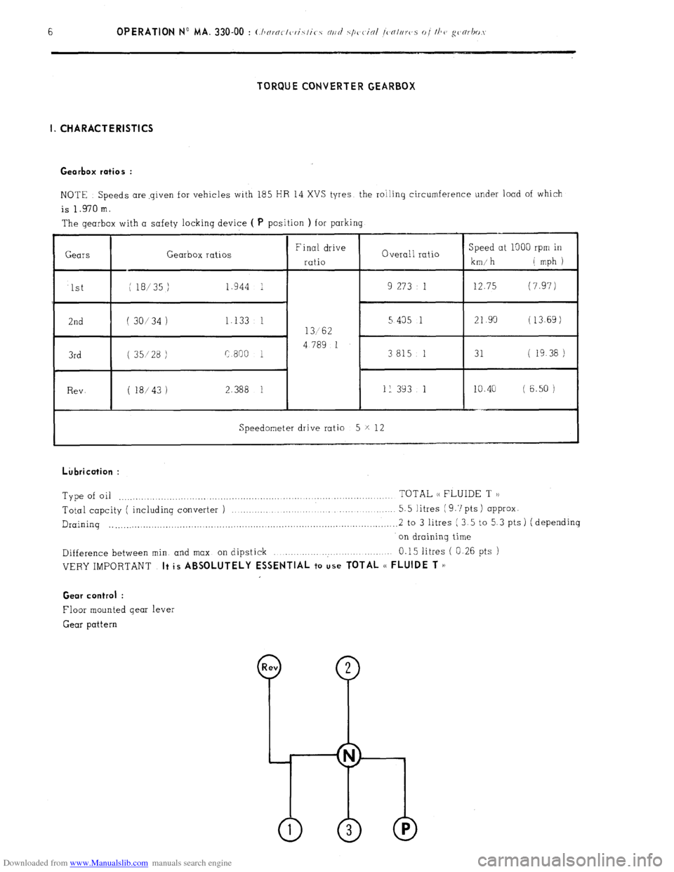
Downloaded from www.Manualslib.com manuals search engine TORQUECONVERTERGEARBOX
I. CHARACTERISTICS
Gearbox ratios :
NOTE Speeds are-given for vehicles with 185 HR 14 XVS tyres the roiling circumference under load of which
is 1.970 m.
The gearbox with a safety locking device ( P
position ) for parking
Gearbox ratios
Speedometer drive ratio 5 X 12 Lkbrication :
Type of oil TOTAL (( FLUIDE T )) ,......._._ ,..,.,_......._..,.............._..,_....,.,...._.. .._..._._._...........
Total capcity ( including converter ) .._ ,..,.
5.5 litres ( 9.7 pts ) approx.
Draining . . .._.__........_..................................................................................... 2 to 3 litres ( 3.5 to 5.3 pts ) ( depending
on draining time
Difference between min. and max on dipstick .._..... ..:. 0.15 litres ( 0.26 pts )
VERY IMPORTANT It is ABSOLUTELY ESSENTIAL to use TOTAL (( FLUIDE T ))
Gear control :
Floor mounted gear lever
Gear pattern
Page 196 of 394
Downloaded from www.Manualslib.com manuals search engine OPERATION No MA. 330.00 : ( l~nmrtvrisfirs
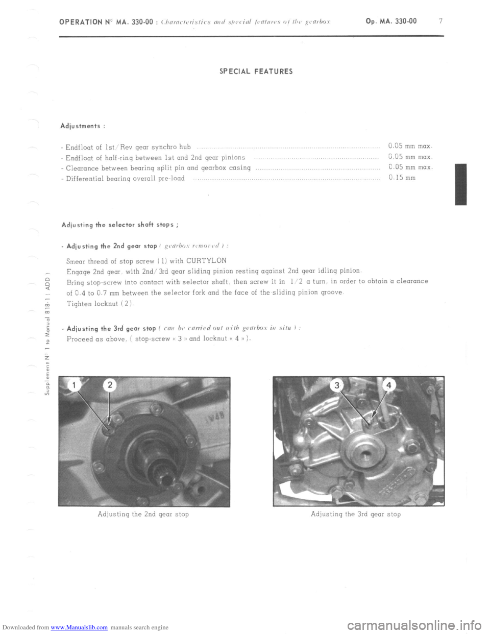
Adiustments :
Endflaot of 1st: Rev gear sjnchro hub 0.35 mm max.
Endfloat of half-ring between
1st and 2nd gear pinions 3.05 nlm nlax.
Clearance between beorinq split pin and gearbox casing c.05 mm nlax.
Differential bearing overoll pre-load 0 15mm Adiusting the selector shaft stops ;
Smear thread of stop screw ( 1) with CURTYLON
Engage 2nd qear. with 2nd/3rd gear sliding pinion resiinq against 2nd gear idling pinion.
$ Bring stop-screw into contaci with selector shaft, then screw it in 1 ‘2 a turn. in order to obtain o clearance
of 0.4 io 0.7 mm between the selector fork and the face of the slidinq pinion groove
7
m Tighten locknut ( 2 ! - Adjusting the 3rd gear stop ( cm lx
rorric,d out rrith pnrbov iu situ I
Proceed ~1s above. j stop-screw (< 3 >) and locknut e 4 1) !.
Page 200 of 394

Downloaded from www.Manualslib.com manuals search engine OPERATION No MA. 330-00 : (horortc,ristir-s NIIC/ .spc,cinl !c,nturc,s of the gc~~,hos Op. MA. 330-00 11
m
03
GEARBOX LOCKING DEVICE FOR PARKING
f
Page 203 of 394
Downloaded from www.Manualslib.com manuals search engine ii. SPECIAL FEATURES
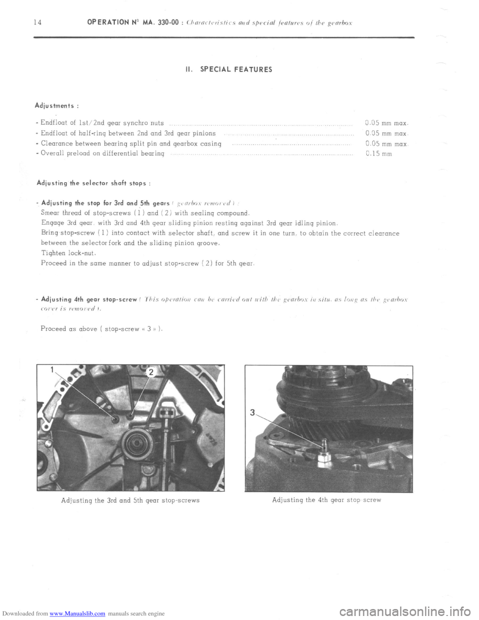
Adjustments :
- Endfloat of lW2nd gear synchio nuts
0.05 mm max.
- Endfloot of half-ring between 2nd and 3rd gear pinions GO5 mm mox
- Clearance between bearing split pin and gearbox casing
0.05 mm nlax.
- Overall prelood on differential bearinq
0.15 mnl Adjusting the selector shaft stops :
. Adjusting the stop for 3rd and 5th gears / ,g< nrhov lI~n,r,, vd ,
Smear thread of stop-screws (1 ) and ( 2) with sealing compound.
Engage 3rd qear with 3rd and 4th qeor sliding pinion resting against 3rd gear idling pinion.
Bring,stop-screw ( 1) into contact with selector shaft, and scw.v it in one turn, to obtain the correct clearance
between the selector fork and the sliding pinion groove.
Tighten lock-nut.
Proceed in the some manner to adjust stop-screw ( 2) for 5th qear.
Adjusting the 3rd and 5th gear stop~screws
Page 236 of 394
Downloaded from www.Manualslib.com manuals search engine OPERATION No MA. 410-O : ( /,c
1
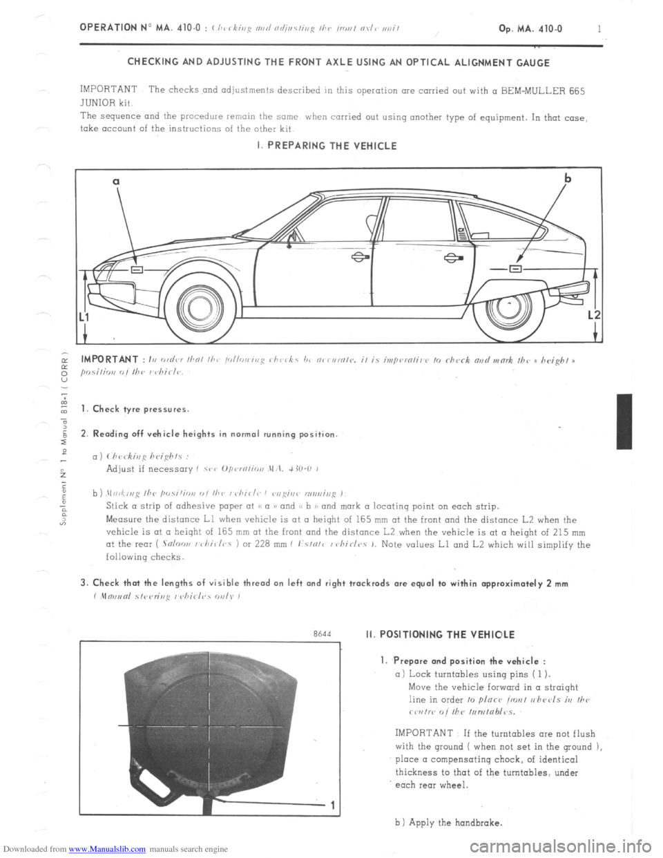
CHECKING AND ADJUSTING THE FRONT AXLE USING AN OPTICAL ALIGNMENT GAUGE
IMPORTANT The checks and adjustments described in this operation are carried out with a BEM-MULLER 665
JUNIOR kit
The sequence and
the procedure remain the same when carried out using another type of equipment. In that case,
take account of the instructions of the other kit I. PREPARING THE VEHICLE
cl
b
-.
I t 1. Check tyre pressures.
2. Rending off vehicle heights in normal running position
c,)
b ) .\I ri,f,,,g /he ,w.s;‘;o,,
Measure the distance Ll when vehicle is at II height of 165 mm at the front and the distance L2 when the
vehicle is at CL height of 165 mm at the front and the distance L2 when the vehicle is at a height of 215 mm
at the rear ( .Snloo,, I vhi~/r,s 1 or 228 mm I I:.s/o/c / chirlr,. 1. Note values Ll and L2 which will simplify the
following checks. 3. Check that the lengths of visible thread on left and right trackrods are equal to within approximately 2 mm
r .Mm,,tnl 51<,<,r;r,,q I <,hirl?s WI). )
r
Rh‘td Ii. POSITIONING THE VEHIOLE
7
-1 1. Prepare and position the vehicle :
a) Lock turntables using pins ( 1 ).
Move the vehicle forward in a straight
line in order 10 plnce ironl r,hccls iv
Ihe
rwrtw o/’ fhC /,,n,tab/~s.
IMPORTANT If the turntables ore not flush
with the ground ( when not set in the ground ),
place a compensating chock, of identical
thickness to that of the turntables, under
each rear wheel.
b 1 Apply the hondbrake.
Page 237 of 394
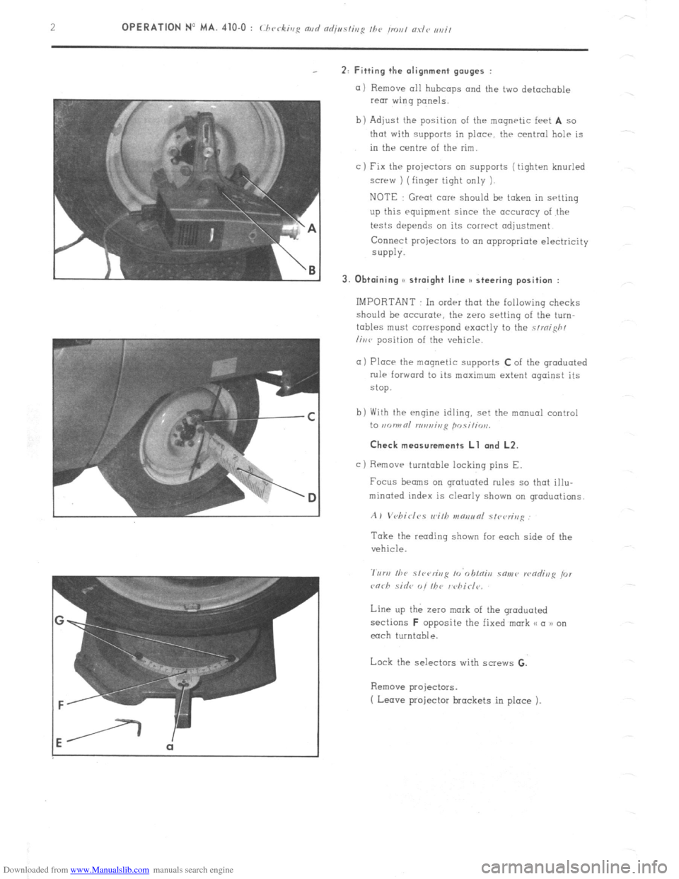
Downloaded from www.Manualslib.com manuals search engine 2: Fitting the alignment gauges :
a) Remove all hubcaps and the two detachable
rear wing panels.
b) Adjust the position of the magnetic feet
A so
that with supports in place, thr central help is
in the centre of the rim.
c ) Fix the projectors on supports ( tighten knurled
screw ) (finger tight only 1.
NOTE Great care should be taken in setting
up this equipment since the accuracy of the
tests depends on its correct adjustment
Connect projectors to on appropriate electricity
SUPPlY.
3. Obtaining S( straight line )I steering position :
IMPORTANT In order that the following checks
should be accurate, the zero setting of the turn-
tables must correspond exactly to the strnifih/
liwv position of the vehicle.
a) Place the magnetic supports C of the graduated
rule forward to its maximum extent against its
stop.
b) With the engine idling, set the manual control
to ,KJWRl n,n,,ir,ji posili, ,,,.
Check measurements Ll and L2.
c)
Removr turntable locking pins E.
Focus beams on grotuoted rules so that illu-
minated index is clearly shown on graduations.
A) Vebirlc,s wilh v~aeunl slvvrin,~
Take the reading shown for each side of the
vehicle.
Line up the zero mark of the graduated
sections
F opposite the fixed mark << a n on
each turntable.
Lock the selectors with screws G.
Remove projectors.
( Leave projector brackets in place ).
Page 238 of 394
Downloaded from www.Manualslib.com manuals search engine Op. MA. 410.0 3
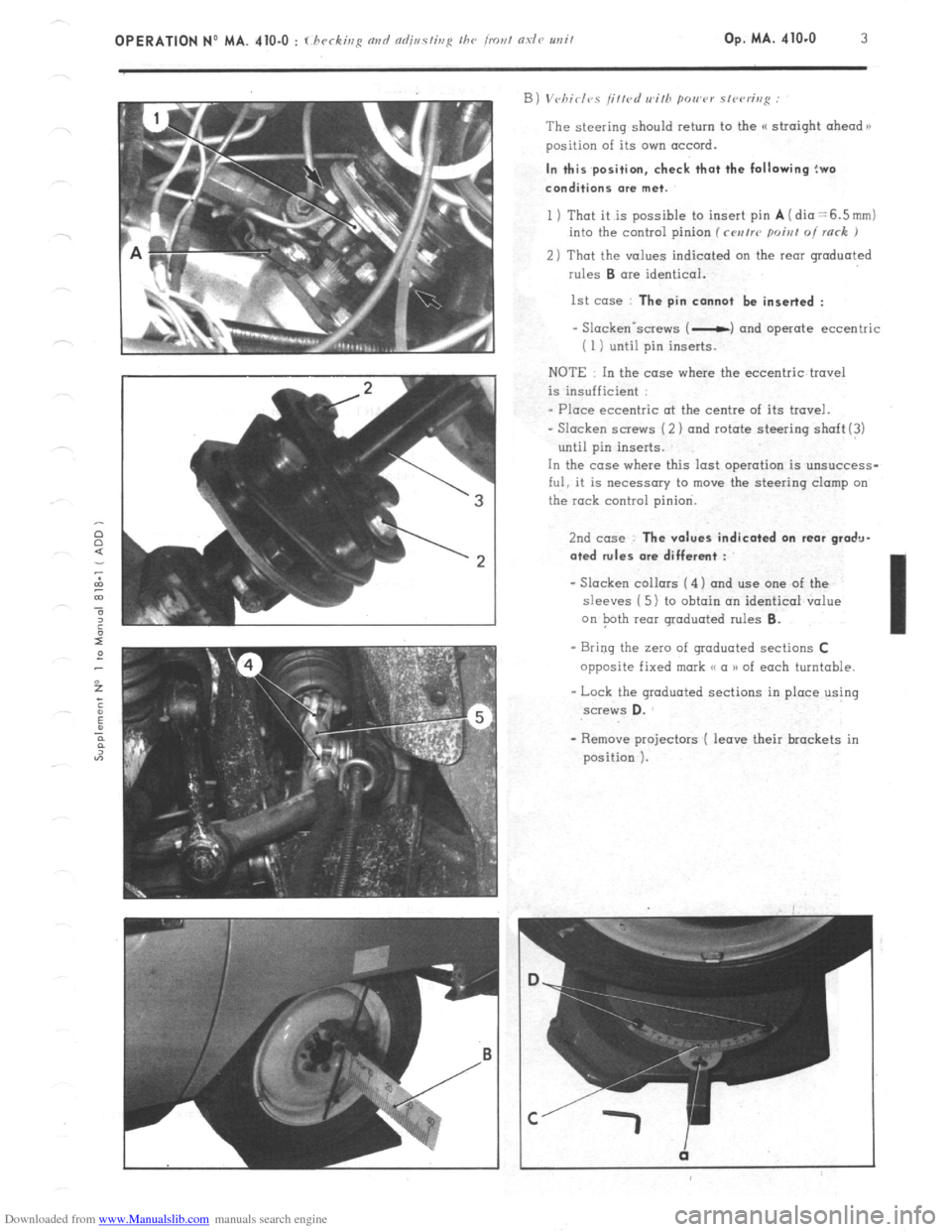
The steering should return to the (( straight ahead n
position of its own accord. In this position, check that the following !wo
conditions me met.
1 ) That it is possible to insert pin A (dia =6.5mm)
into the control pinion (rwrrr poiat oi rack J
2) That the values indicated on the rear graduated
rules B ore identical.
1st case : The pin cannot be inserted :
- Slackenvscrews ( -c) and operate eccentric
i 1 i until pin inserts.
NOTE In the case where the eccentric travel
is insufficient :
- Place eccentric ot the centre of its travel.
- Slacken screws (2 ) and rotate steering shaft(!)
until pin inserts.
In the case where this last operation is unsuccess-
ful, it is necessary to move the steering clamp on
the rock control pinion.
2nd case : The values indicated on rear gradu-
ated rules ore different :
- Slacken collars ( 4) and use one of the
sleeves ( 5 1 to obtain an identical value
on Path rear graduated rules 6.
- Bring the Z~IO of graduated sections C
opposite fixed mark <( a )I of each turntable.
- Lock the graduated sections in place using screws D.
Page 239 of 394
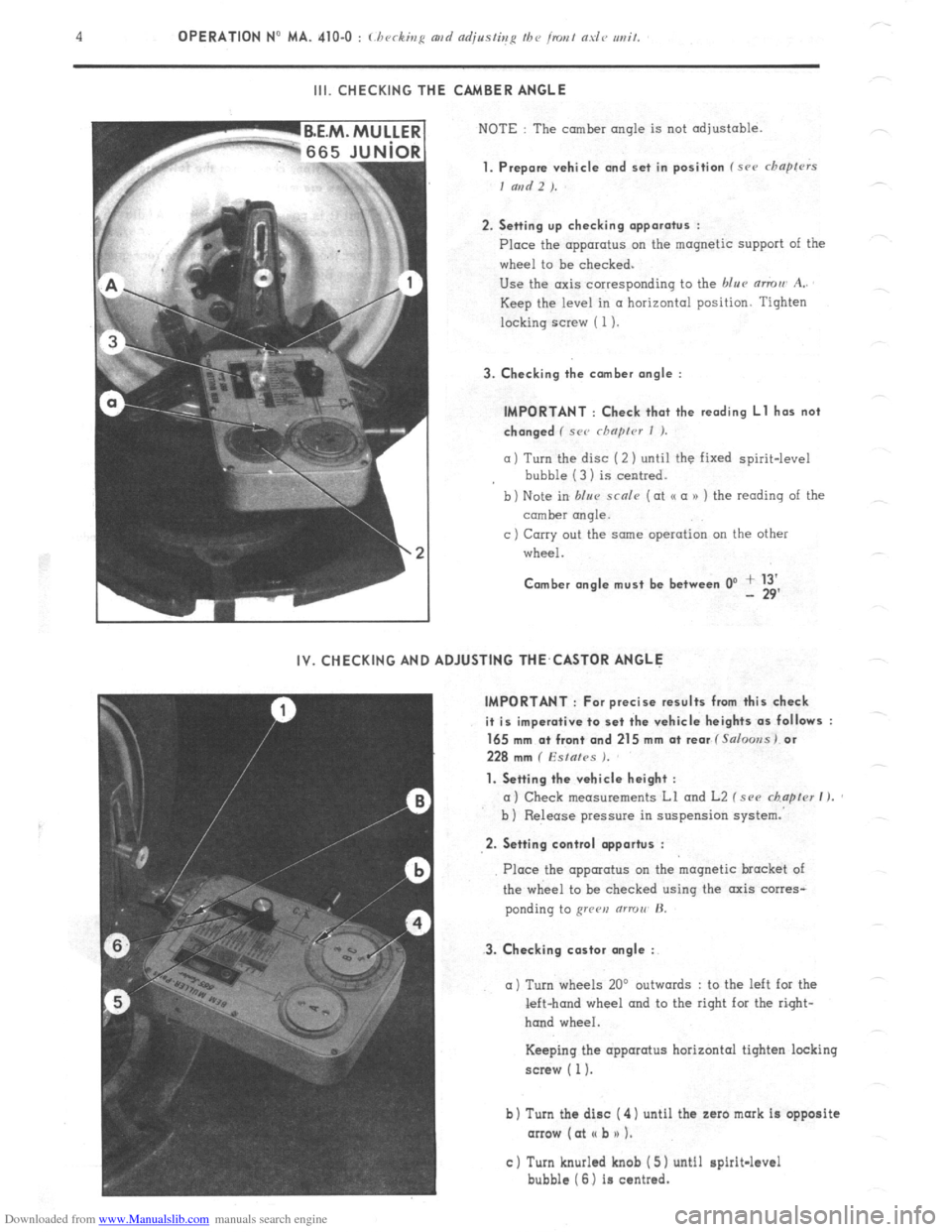
Downloaded from www.Manualslib.com manuals search engine III. CHECKING THE CAMBER ANGLE
NOTE : The camber angle is not adjustable.
1. Prepare vehicle and set in position f src chapfrrs
I and 2 ).
2. Setting up checking apparatus :
Place the apparatus on the magnetic support of the
wheel to be checked.
Use the axis corresponding to the blue mmu A..
Keep the level in a horizontal position. Tighten
locking screw ( 1).
3. Checking the comber angle :
IMPORTANT : Check that the reading Ll has not
changed ( SC<’ rhnprcr I ).
a) Turn the disc (2 ) until the fixed spirit-level
bubble (3 1 is centred.
b) Note in blur scnle (at o a n ) the reading of the
comber rmqle.
c ) Carry out the same operation on the other
wheel.
Comber angle must be between 0’ + 13’ - 29’
IV. CHECKING AND ADJUSTING THE,CASTOR ANGLE
IMPORTANT : For precise results from this check
it is imperative to set the vehicle heights as follows :
165 mm a+ front and 215 mm at rear f Salooss) or
228 mm ( Esfafes ).
1. Setting the vehicle height :
a) Check measurements Ll and L2 f see chapter I ).
b ) Release pressure in suspension system.
2. Setting control opportus :
3. Checking castor angle :
Place the apparatus on the magnetic bracket of
the wheel to be checked using the axis corres-
ponding to grren (ITTOII’ H.
a) Turn wheels 20’ outwards : to the left for the
left-hand wheel and to the right for the right-
hand wheel.
Keeping the apparatus horizontal tighten locking
screw ( 1).
b) Turn the disc ( 4) until the zaro mark is opposite
arrow (at I( b n 1.
c) Turn knurled knob ( 5) until spirit-level
bubble (6) is centred.
Page 242 of 394
Downloaded from www.Manualslib.com manuals search engine OPERATION No MA. 410-O : I hvr-6iq n,,d od;n.s/isg /hc /~,a, nrle uei/ Op. MA. 410-O 7
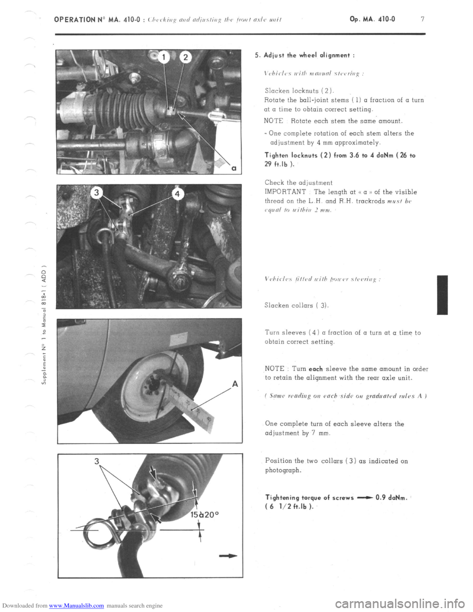
’ 15b20° 5. Adiust the wheel alignment :
\‘chirl‘,s II ilh mw,r,ol s/wrh,i: :
Slacken locknuts (2 ).
Rotate the ball-joint stems ( 1) a froctmn of a turn
at a time to obtain correct setting.
NOTE Rotate each stem the same’ amount.
- One complete rotation of each stem alters the
adjustment by 4 mm approximately. Tighten locknuts (2) from 3.6 to 4 daNm (26 to
29 ft.lb ).
Check the adjustment
IMPORTANT The length at (< a n of the visible
thread on the L.H. and R.H. trackrods ,,,r,s/ lx,
vq,,nl IO rrithin 2 ,,,7,,,
Slacken collars ( 3).
Turn sleeves (4) ~1 fraction of a turn at a time to
obtain correct setting.
NOTE Turn each
sleeve the same amount in order
to retain the oiiqnment with the rear axle unit.
I Son<, wcidisp on varh sidv o,, gmd,,lrrn/r,d rules A I
One complete turn of each sleeve alters the
adjustment by 7 mm.
Position the two collars ( 3) (IS indicated on
photograph. Ti.ghtening torque of screws - 0.9 daNm.
( 6 l/2 ft.lb ).
Page 243 of 394
Downloaded from www.Manualslib.com manuals search engine a OPERATION N’ MA. 410-O : (./~rrkiq N,,I/
VI. CHECKING AND ADJUSTING THE STEERING GEOMETRY
The crossmember supporting the steering has slots at its fixing point on the front subframe.
Any vertical movement of this crossmember alters the steering geometry.
WARNING
This operation is only to
be carried out in certain ccxses such as
-accidental impact, with repercussions on the steering system.
-work on the vehicle entoiling removal of steering crossmember.
- vehicle with poor
road stability ( p oar stright-line stability) 01 with excessive tyre weor.
CHECKING
1, Prepare the vehicle. as for checking front wheel
alignment ( Srr ~ho/,lvr
V I.
NOTE
A ) \In,,unl ~fi~<,r;,,~ I chiclvs :
With the steering in the /< straightahead 1)
position. lock the steering using CI commercially
available tool ( FACOM _ MULLER -WILMONDA)
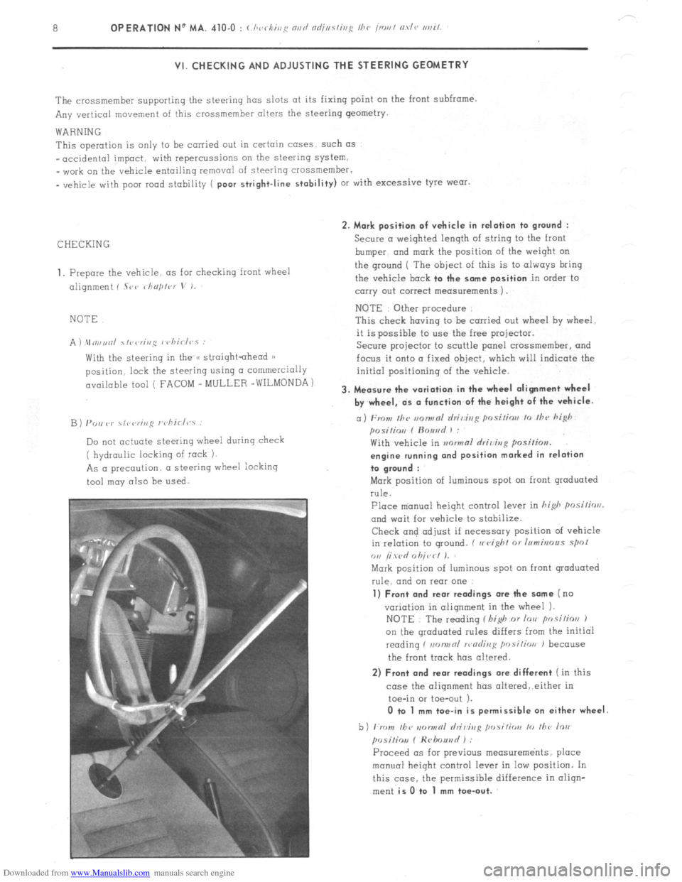
B) PO,, P)’ \,r,rr;ng r’cliirl<,.s :
Do not actuate steering wheel during check
( hydraulic locking of rock 1.
As a precaution. a steering wheel iocking
tool may also be
used. 2. Mark position of vehicle in relation to
ground :
Secure a weighted length of string to the front
bumper. and
mark the position of the weiqht on
the ground ( The
object of this is to always bring
the vehicle
bock to the some position in order to
carry out correct measurements 1.
NOTE Other procedure
This check having to be carried out wheel hy wheel.
it is possible to use the free projector.
Secure projector to scuttle panel crossmemher, and
focus it onto a fixed object, which will indicate the
initial positioning of the vehicle.
3. Measure the variation in the wheel alignment wheel
by wheel, ds o function of the height of the vehicle.
a) From Ihc m~nwnl rlri,:ir,g posi/ior, lo /hc hi@
posilio,, f ftouad 1 :
With vehicle in mwmal rlriving position.
engine running ond position marked in relation
to groond :
Mark position of luminous spot on front graduated
rule.
Place m’anual height control lever in hi&
posilirrrl.
and wait for vehicle to stabilize.
Check and adjust if necessary position of vehicle
in relation to ground. ( II
eight 01 Inmbrous spol
ou /i wd 0 hit,< I J.
Mark position of luminous spot on front graduated
rule. and on rear one
1) Front and rear readings ore the some (no
variation in alignment in the wheel 1.
NOTE : The reading f I,i$ or lorr posilios J
on the qroduated rules differs from the initial
reading f non,,nl >r,nrlinl:
position J because
the front track has altered.
2) Front and rear readings ore different ( in this
case the alignment has oltered,.either in
toe-in or toe-out ).
0 to 1 mm toe-in is permissible on either wheel
b) ,:rr ,,I, /bv IIDIINRI hi&g ,,osi,;orr lo ,I,<, lo,,
posiliov f Hrlmuad ) :
Proceed OS for previous measurements, place
manual height control lever in low position. In
this case. the permissible difference in oliqn-
ment
is O.to 1 mm toe-out.