engine Citroen CX 1978 1.G Repair Manual
[x] Cancel search | Manufacturer: CITROEN, Model Year: 1978, Model line: CX, Model: Citroen CX 1978 1.GPages: 394
Page 61 of 394
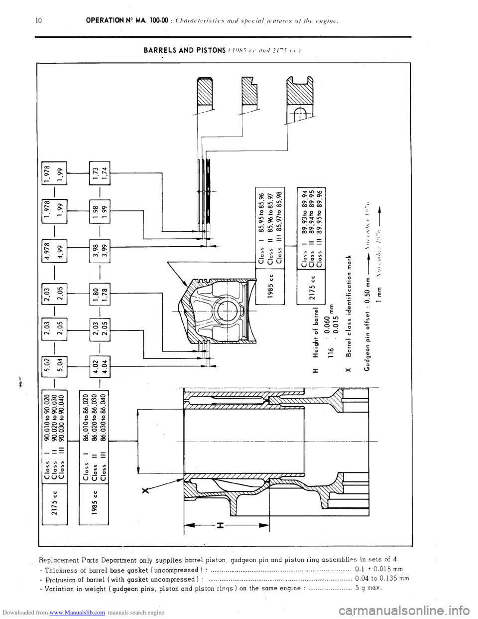
Downloaded from www.Manualslib.com manuals search engine BARRELS AND PISTONS c 1()8j cc nr/cl ?/‘i cc I
t
:
0
ln
d
. .
E
-0”
(3
I x
Replacement Parts Department only supplies barrel piston, gudgeon pin and piston ring assemblies in sets of 4.
- Thickness of barrel base gasket ( uncompressed ) : ............................................................................ 0.1 i 0.015 mm - profusion of barrel (with gasket uncompressed ) : .............................................................................. 0.04 to 0.135
mm
- Variation in weight ( gudgeon pins, piston and piston rings ) on the same engine : ........................
5 g max.
Page 62 of 394

Downloaded from www.Manualslib.com manuals search engine Op. MA. 100-00
BARRELS AND PISTONS (2350 cc 1
-I
-I
The. Replacement Parts Department only supplies barrel, piston, gudgeon pin and piston ring assemblies in
sets of 4.
. Thickness of barrel base gasket ( uncompressed ) : . . . . . . . . . . . . . .._.._....................................................... 0.1 2 JO.O1O mm
protrusion of barrel ( with gasket uncompressed ) : _..._,_,...,._,............................................................ 0.045 to 0.115 mm
- Variation in weight (pistons, gudgeon pins, and gudgeon pin circlips ) on the same engine : . . . 5 g max.
Page 63 of 394
Downloaded from www.Manualslib.com manuals search engine 5. Cylinder head :
Aluminium alloy, with hemispherical combustion chambers.
- Original height : . . . . . . . . . . . . . . . . . . . . . . . . . . . . . . . . . . . . . . . . . . . . . . . . . . . . . . . . . . . . . . . . . . . . . . . . . . . . . . . . . . . . . . . . . . . . . . . . . . . . . . . . . . . . . . . . . . . . . . . . ........................ 90 mm
- Overall flatness to within : . . . . . . . . . . . . . . . . . . . . . . . . . . . . . . . . . . . . . . . . . . . . . . . . . . . . . . . . . . . . . . . . . . . . . . . . . . . . . . . . . . . . . . . . . . . . . . . . . . . . . . . . . . . . . . . . . . . . . . . . ...... 0.10 mm
- Flatness between fixing holes to within : . . . . . . . . . . . . . . . . . . . . . . . . . . . . . . . . . . . . . . . . . . . . . . . . . . . . . . . . . . . . . . . . . . . . . . . . . . . . . . . . . . . . . . . . . . . . . . . . . . . . . 0.025 mm
a) Head gasket :
Round clinching (diameter = 92.5 mm ), the identification mark (( CEFILAC 1) or (( COOPERS )) towards the
cylinder head ( 1985 cc ).
Oval clinching; the identification mark (( CEFILAC 1) towards the cylinder head (2175 cc ).
Round clinching (diameter = 96.5 mm ), the identification mark (( CEFILAC )) towards the cylinder head (2350 cc).
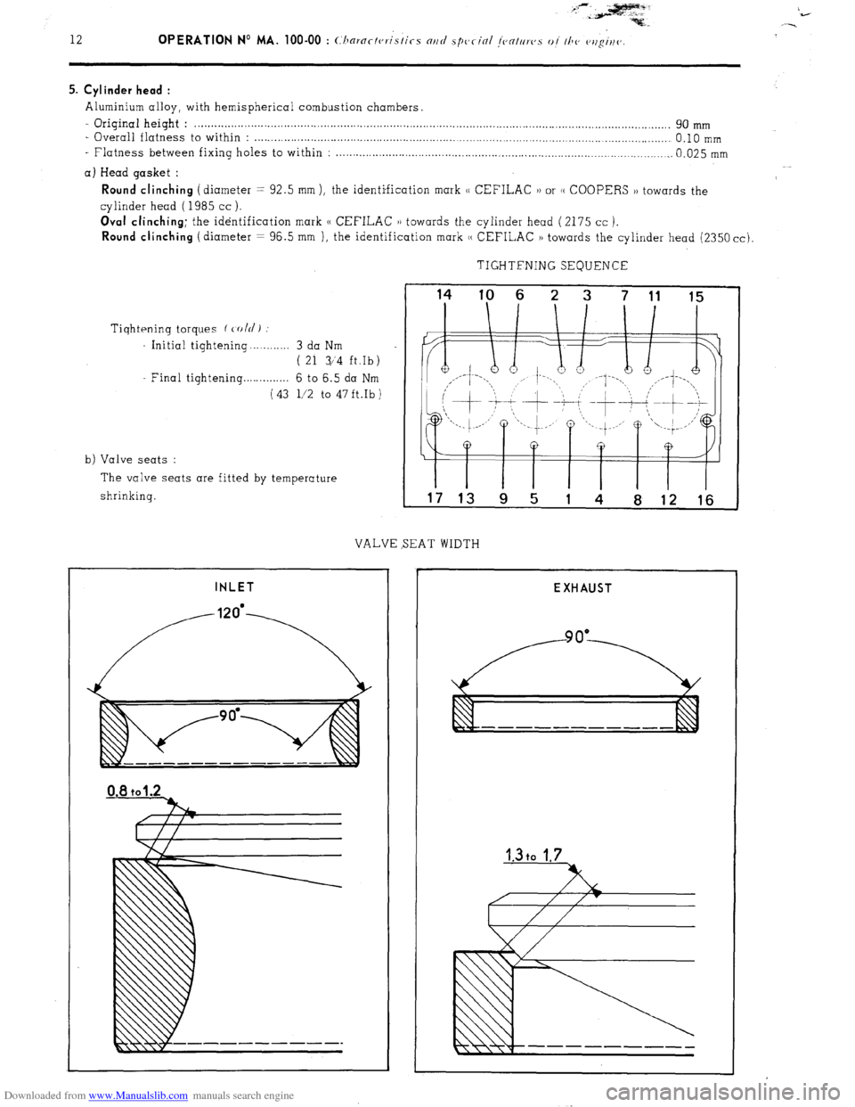
TIGHTFNING SEQUENCE
Tiqhtening torques f cold)
Initial tightening . . . . . . . . . . 3 da Nm
( 21 3/‘4 ft.Ib)
Final tightening . . . . . . . . . . . . . 6 to 6.5 da Nm
(43 l/2 to 47ft.Ib)
b) Valve seats :
The valve seats are fitted by temperature
shrinking.
VALVE SEAT WIDTH
INLET
I I I I I I T
17 13 9 5 1 4 8 12 16
EXHAUST
Page 64 of 394

Downloaded from www.Manualslib.com manuals search engine Op. MA. 100-00 13
c) Valve guides and valves :
5
7 q+- j
-- - -
Y
NOTE : Inlet. and exhaust valves are fitted with oil-seals.
Page 65 of 394
Downloaded from www.Manualslib.com manuals search engine d) Valve springs :
The inlet and exhaust valve springs are identical.
Characteristics :
- Diameter of wire : . . . . . . . . . . . . . . . . . . . . . . . . . . . . . . . . . . . . . . . . . . . . . . . . . . . . . . . . . . . . . . . . . . . . . . . . . . . . . . . . . . . 4.6 + 0.02 mm
Interior diameter : . . . . . . . . . . . . . . . . . . . . . . . . . . . . . . . . . . . . . . . . . . . . . . . . . . . . . . . . . . 25 2 0.2 mm
- Length of spring under load : . . . . . . . . . . . . . . . . . . . . . . . . . . . . . . . . . . . . . . . . . . . . . . . . .
1 39mm(load=m40t2,8kg)
30.6 mm ( load = 84 ~‘1.8 kg )
Coating : ._._................................................................................................ Red or blue varnish
e) Upper spring cups : Identical inlet and exhaust.
f ) Retaining clips : Identical inlet and exhaust
6. Timing :
a) Camshaft :
Chain-driven camshaft, resolving in three cupro -lead bearings.
- Camshaft end-float (a,//>~ I /hi<-krlc~ss a,/ !/o,/s(, I: 0.05 to 0.30 mm
- Thickness of flange : . . . . . . . . . . . . . . . . . . . . . . . . . . . . . . . . . . . . . . . . . . . . . . . . . . . . . . . . . . . . . . . . . 5.44 to 5.46 mm
- Amount of cam lift :
Inlet : . . . . . . . . . . . . . . . . . . . . . . . . . . . . . . . . . . . . . . . . . . . . . . . . . . . . ..__.._..._ _.;._.; .._...._ ..__.___.., 6.63
2’0.02 mm
Exhaust : ___._._..._.........................................................................................,... 6.14 + ‘0.02 mm
WARNING :
Never attempt to rotate the engine by means of the camshaft pulley fixing nut.
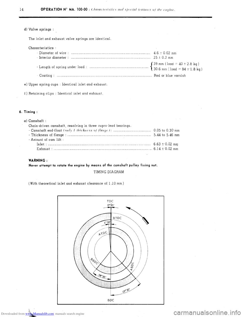
TIMING DIAGRAM
(With theoretical inlet and exhaust clearance of 1 .lO mm )
Page 66 of 394
Downloaded from www.Manualslib.com manuals search engine OPERATION No MA. 100-00 : Characteristics and special features of the engine. Op. MA. 100.00 15
b) Timing chain :
- Clearance between the chain and the chain guide : . . . . . . . . . . . . . . . . . . . . . . . . . . 0.10 to 0.50 mm
c) Rockers :
- Length of push rods :
- Inlet : . . . . . . . . . . . . . . . . . . . . . . . . . . . . . . . . . . . . . . . . . . . . . . . . . . . . . . . . . . . . . . . . . . . . . . . . . . . . . . . . . . . . . . . . . . . . . . 189.10 ‘, Og’Q5 mm
- Exhaust : . . . . . . . . . . . . . . . . . . . . . . . . . . . . . . . . . . . . . . . . . . . . . . . . . . . . . . . . . . . . . . . . . . . . . . . . . . . . . . . . . . . . . . . 213.35 + 0.3
- 0.75 mm
- Maximum out of true of pushrods : . . . . . . . . . . . . . . . . . . . . . . . . . . . . . . . . . . . . . . . . . . . . . . . . . . . . . . . 1 mm
- Rocker clearance (engine cold) :
-Inlet : . . . . . . . . . . . . . . . . . . . . . . . . . . . . . . . . . . . . . . . . . . . . . . . . . . . . . . . . . . . . . . . . . . . . . . . . . . . . . . . . . . . . . . . . . . . . . . 0.15mm
- Exhaust : . . . . . . . . . . . . . . . . . . . . . . . . . . . . . . . . . . . . . . . . . . . . . . . . . . . . . . . . . . . . . . . . . . . . . . . . . . . . . . . . . . . . . . . . 0.20 mm
7. Flywheel :
2 - Distance between the clutch mechanism thrust face, and the 0 u clutch disc thrust face : . . . . . . . . . . . . . . . . . . . . . . . . . . . . . . . . . . . . . . . . . . . . . . . . . . . . . . . . . . . . . . . . . . . . . . . . . . . . 0.5 -is mm
7
co
G NOTE : It is essential to fit the diaphragm or flywheel mounting screws with LOCTITE FRENETANCH.
x
z - Correct fitting of starter ring : non machined face of the ring facing the flywheel shouldering.
s
2
E 8. Lubrication system :
5
z
6%
- Grade of oil . . . . . . . . . . . . . . . . . . . . . . . . . . . . . . . . . . . . . . . . . . . . . . . . . . . . . . . . . . . . . . . . . . . . . . . . . . . . . . . . . . . . . . . . . . . . . . . TOTAL ALTIGRADE GTS 20/W 50
2
- Capacity of sump :
- after dismantling : . . . . . . . .._................................................................. 5.800 litres ( IO.2 pts )
- after draining and changing the filter : : . . . . . . . . . . . . . . . l......................... 5.306 litres ( 9.3 pts )
- after draining : . . . . . . . . . . . . . . . . . . . . . . . . . . . . . . . . . . . . . . . . . . . . . . . . . . . . . . . . . . . . . . . . . . . . . . . . . . . . . . . . . . . 4.650 litres ( 8.2 pts )
- Oil pressure :
(At a temperature of 100 +‘S’ C)
- at 2000 rpm : . . . . . . . . . . . . . . . . . . . . . . . . . . . . . . . . . . . . . . . . . . . . . . . . . . . . . . . . . . . . . . . . . . . . . . . . . . . . . . . . . . . . . . . 3 .bar min. ( 43.5 psi )
- at 4000 rpm : . . . . . . . . . . . . . . . . . . . . . . . . . . . . . . . . . . . . . . . . . . . . . . . . . . . . . . . . . . . . . . . . . . . . . . . . . . . . . . . . . . . . . . 4 to 5 bar ( 58 to 72 l/2 psi )
- Calibration of pressure switch : . . . . . . . . . . . . . . . . . . . . . . . . . . . . . . . . . . . . . . . . . . . . . . . . . . . . . . . . . . . . . . . . 475 to 675 mbar ( 7 to 9.8 psi )
(warning lamp goes oat)
- Calibration of temperature switch (CX 2000 e Jan. 1975) : . . . . 1... 147’ to 150’ C
(warning lamp goes comes on)
(All CX vehicles Jan. 1975 -) : 135” to 138’ C
(warning lamp comes on )
- Calibration of relief valve spring :
- length of spring fully compressed : . . . . . . . . . . . . . . . . . . . . . . . . . . . . . . . . . . . . 31 mm
- length of spring under load of 10.9 kg : . . . . . . . . . . . . . . . . . . . . . . . . . . . . . . . . . . . . . . . . . . 42 mm
- Filter cartridge :
- calibration of (( by-pass )) valve : . . . . . . . . . . . . . . . . . . . . . . . . . . . . . . . . . . . . . . . . . . . . . . . . . . . . . . 550 mbar ( 8 psi )
NOTE : When changing the filter cartridge, check the cleanliness of the seal and’the contact area on the filter
housing.
- For removing and fitting the cartridge : . . . . . . . . . . . . . . . . . . . . . . . . . . . . . . . . . . . . . . . . . . . . . . . . . . . . Use Tool 6002-T
Page 67 of 394

Downloaded from www.Manualslib.com manuals search engine 16 OPERATION No MA. 100-00 : Ch aractcristics and special features of the engine.. LUBRICATION SYSTEM
Page 68 of 394
Downloaded from www.Manualslib.com manuals search engine OPERATION No MA. 100-00 : Characteristics and special jeafruvs oj the cvlghv.
Op. MA. 100-00 17
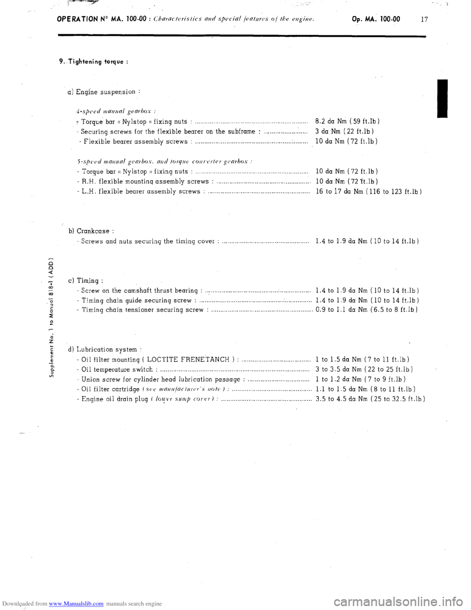
9..Tightening torque :
a) Engine suspension :
4-.spc~~d manrlal gearbox :
7 Torque bar (( Nylstop )) fixing nuts : .............................................................. 8.2 da Nm ( 59 ft.Ib )
- Securing screws for the flexible bearer on the subframe ; ........................ 3 da Nm ( 22 ft.lb)
- Flexible bearer assembly screws :
..................................................... .
........ 10 da Nm (72 ft.lb)
S-sp~~tl n1m11ra1 gca~box. and forq~~c cour,c~rtrr gc~arkos
- Torque bar (( Nylstop )) fixing nuts : . . . . . . . . . . . . . . . . . . . . . . . . . . . . . . . . . . . . . . . . . . . . . . . . . . . . . . . . . . . . . . 10 da Nm (72 ft.lb)
- R:H. flexible mountinq assembly screws : . . . . . . . . . . . . . . . . . . . . . . . . . . . . . . . . . . . . . . . . . . . . . . . . . . . . 10 da Nm ( 72 ‘ft.lb )
- L.H. flexible bearer assembly screws : . . . . . . . . . . . . . . . . . . . . . . . . . . . . . . . . . . . . . . . . . . . . . . . . . . . . . . . . 16 to 17 da Nm ( 116 to 123 ft.lb )
b) Crankcase :
Screws and nuts securing the timing cover : . . . . . . . . . . . . . . . . . . . . . . . . . . . . . . . . . . . . . . . . . . . . . . 1.4 to 1.9 da Nm (10 to 14 ft.lb)
c) Timing :
- Screw on the camshaft thrust bearing : . . . . . . . . . . . .._............................................ 1 .4 to 1 .9 da Nm ( 10 to 14 ft.lb )
- Timing chain guide securing screw : . . . . . . . . . . . ..__................................ . . . . . . . . . . . . . . .
1.4 to 1.9 da Nm ( 10 to 14 ft.lb)
- Timing chain tensioner securing screw : . . . . . . . . . . . . . . . . . . . . . . . . . . . . . . . . . . . . . . . . . . . . . . . . . . . . . . . 0.9 to 1 .I da Nm (6.5 to 8 ft.lb )
d) Lubrication system :
- Oil filter mounting ( LOCTITE FRENETANCH ) : ......................................
1 to 1 .5 da Nm ( 7 to 11 ft.lb )
- Oil temperature switch : .................................................................................. 3 to 3.5 da Nm ( 22 to 25 ft.lb )
- Union screw for cylinder head lubrication passage : ..................................
1 to 1 .2 da Nm ( 7 to 9 ft.lb )
- Oil filter cartridge ( SPV
wnrt/r]nctc/rer‘s rmte ) : ............................................ 1 .l to 1 .5 da Nm ( 8 to 11 ft.lb )
- Engine oil drain plug ( lo~!,c,r s/t~/p
co/‘cr) : .................................................. 3.5 to 4.5 da Nm (25 to 32.5 ft.lb)
Page 69 of 394
Downloaded from www.Manualslib.com manuals search engine OPERATION No MA. 112-O : ChcJcking and adjusting the valrv mechanism. Op. MA. 112-O
1
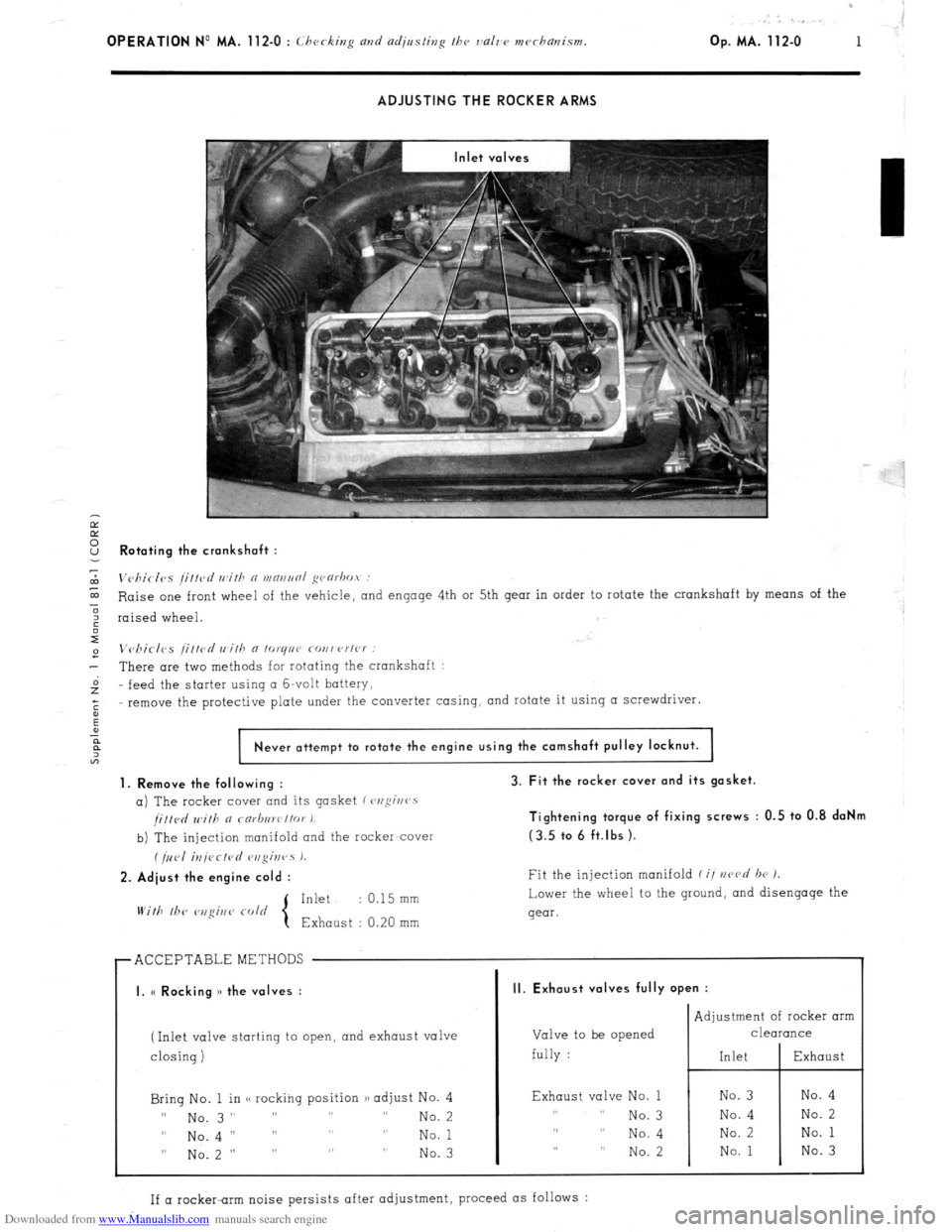
ADJUSTING THE ROCKER ARMS
Ir
E
2 Rotating the crankshaft :
7
m
Vc,birlvs /i//cd wifh n WRIINRI ~varbot :
E Raise one front wheel of the vehicle,
and engage 4th or 5th gear in order to rotate the crankshaft by means of the
3
6 raised wheel.
I
e Vchirlcs /ittcd wilh a lo~qnr covwrlc~ :
- There are two methods for rotating the crankshaft :
Gz feed the
starter using CI G-volt battery,
;
remove the protective plate under the converter casing, and rotate it using a screwdriver.
:
Never attempt to rotate the engine using the camshaft pulley locknut.
1. Remove the following :
a) The rocker cover and its gasket (~,ofii~rr~s
/i//d Will, a rarb,,wt/or I.
b) The injection manifold and the racker-cover
(/,,<,I iU/<~CfPd r,zgir,rs 1.
2. Adiust the engine cold :
Inkt : 0.15 mm
With lb<‘
3. Fit the rocker cover and its gasket.
Tightening torque of fixing screws : 0.5 to 0.8 daNm
(3.5 tc. 6 ft.lbs ).
Fit the injection manifold f i/ nczvd br 1.
Lower the wheel to the ground,
and disengage the
gear.
r ACCEPTABLEMETHODS
I I
I. (< Rocking )> the valves :
(Inlet valve starting to open, and exhaust valve
I
closing) closing)
Bring No. 1 in <, rocking position /) adjust No. 4 Bring No. 1 in <, rocking position /) adjust No. 4
II II
No. 3” ” ” ” No. 3” ” ” ” No. 2 No. 2
0 0
No.4 I’ ” ” ” No.4 I’ ” ” ” No. 1 No. 1
” No.2 ” ” ” ” ” No.2 ” ” ” ” No. 3 No. 3
II. Exhaust valves fully open :
Valve to be opened
fully : Adjustment of rocker arm
CleUKUlCe
Exhaust valve No. 1
,, I, No. 3
,, ,, No. 4
,, ,, No. 2
If a rocker-rim noise persists after adjustment, proceed as follows :
Page 70 of 394
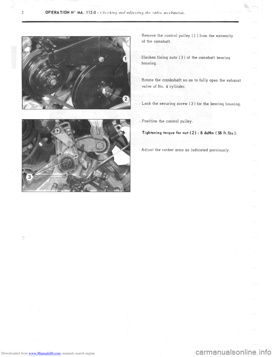
Downloaded from www.Manualslib.com manuals search engine Remove the control pulley ( 1 ) from the extremity
of the camshaft.
SIacken fixing nuts (3 ) of the camshaft bearing
housing.
Rotate the crankshaft so as to fully open the exhaust
valve of No. 4 cylinder.
Lock the securing screw (3 ) for the bearing housing.
Position the control pulley.
Tightening torque for nut (2) : 8 daNm (58 ft.lbs).
Adjust the rocker arms as indicated previously.