Jack Citroen CX 1978 1.G Workshop Manual
[x] Cancel search | Manufacturer: CITROEN, Model Year: 1978, Model line: CX, Model: Citroen CX 1978 1.GPages: 394
Page 4 of 394

Downloaded from www.Manualslib.com manuals search engine Operation
number
VIA. 000
VIA. 00
VIA. 00-600
vlA. 00-655
VIA. 01
WA. 02
MA. 03
MA. 100-00
MA. 112-O
MA. 120-O
MA. 142-000
MA. 142-00
MA. 142-00 a
MA. 142-00 b
MA. 142-00 SI
MA. 142-O
MA. 142-O SD
MA. 144-00
MA. 144-O
MA. 173-O
MA. 210-00
MA. 210-00 a
MA. 210-O
MA. 210-O a
MA. 220-O
MA. 221-O
MA. 230-00
MA. 230-O
MA. 236-O
MA. 312-00
MA. 314-O
MA. 320-00
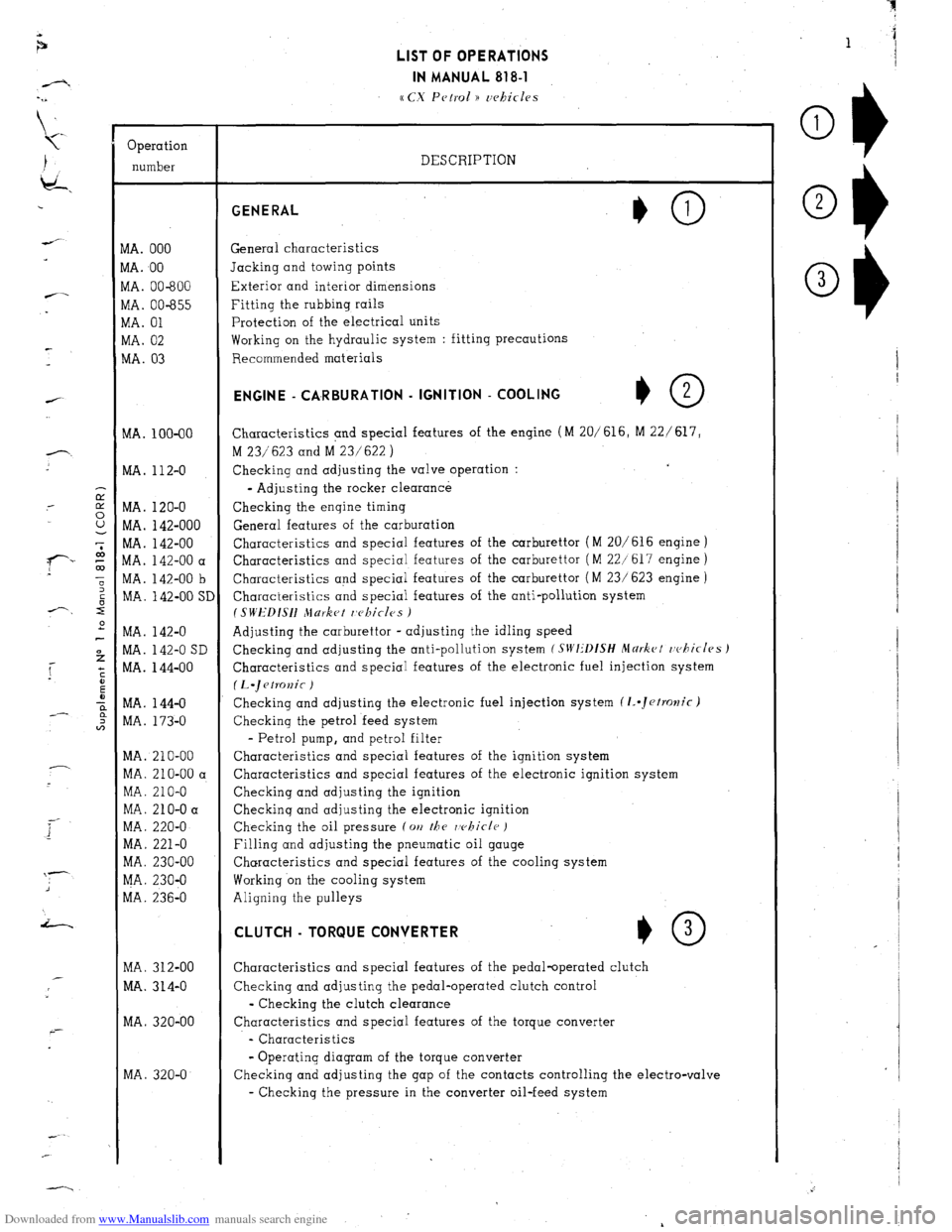
MA. 320-O LIST OF OPERATIONS
IN MANUAL 818-l
cc CX Petrol )) uehicles
DESCRIPTION GENERAL
General characteristics
Jacking and towing points
Exterior and interior dimensions
Fitting the rubbing rails
Protection of the electrical units
Working on the hydraulic system : fitting precautions
Recommended materials ENGINE - CA,RBURATlON - IGNITION - COOLING
+O 2
Characteristics and special features of the engine (M 20/616, M 22/ 617,
M 23/623 and M 23/622 )
Checking and adjusting the valve operation :
- Adjusting the rocker clearance
Checking the engine timing
General features of the carburation
Characteristics and special features of the carburettor (M 20/616 engine )
Characteristics and special features of the carburettor ( M 22/617 engine )
Characteristics and special features of the carburettor ( M 23/ 623 engine )
Characteristics and special features of the anti-pollution system
I SWEDISH Jlurket r,c~kicles )
Adjusting the carburettor - adjusting the idling speed
Checking and adjusting the anti-pollution system
(SIVI:‘DfSH Mdrkct rvhicles J
Characteristics and special features of the electronic fuel injection system
(L.~etKJnic )
Checking and adjusting the electronic fuel injection system (1..Jetrolzic)
Checking the petrol feed system
- Petrol pump, and petrol filter
Characteristics and special features of the ignition system
Characteristics and special features of the electronic ignition system
Checking and adjusting the ignition
Checkinq and adjusting the electronic ignition
Checking the oil pressure (on
the rvhicle )
Filling and adjusting the pneumatic oil gauge
Characteristics and special features of the cooling system
Working on the cooling system
Aligning the pulleys CLUTCH - TORQUE CONVERTER
*O 3
Characteristics and special features of the pedal-operated clutch
Checking and adjusting the pedal-operated clutch control
- Checking the clutch clearance
Characteristics and special features of the torque converter
- Characteristics
- Operating diagram of the torque converter
Checking and adjusting the gap of the contacts controlling the electro-valve
- Checking the pressure in the converter oil-feed system
Page 159 of 394

Downloaded from www.Manualslib.com manuals search engine 4 OPERATION No MA. 210-O : (hcrkir,p or,
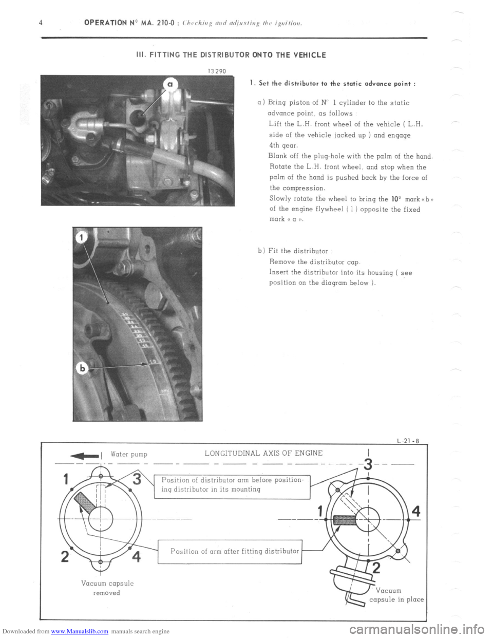
III. FITTING THE DISTRIBUTOR ONTO THE VEHICLE
1. Set the distributor to the static
advance point :
a 1 Bring piston of NC 1 cylinder to the static
advance point, as follows
Lift the L.H. front wheel of the vehicle ( L.H.
side of the vehicle jacked up ) and engage
4th gear.
Blank off the plug-hole with the palm of the hand.
Rotate the L.H. front wheel, and stop when the
palm of the hand is pushed back by the force of
the compression.
Slowly rotate the wheel to bring the 10”
morkabx
of the engine flywheel ( 1) opposite the fixed mark (c a aa.
b) Fit the distributor
Remove the distributor cap.
Insert the distributor into its housing ( see
position on the dioqram below 1.
-, water pump LONGITUDINAL AXIS OF ENGINE
--~-__ -- -- ----~--
Position of distributor arm before position-
ing distributor in its mounting
I
w
Vacuum capsule
removed
capsule in place Position of arm after fitting distributor
Page 263 of 394

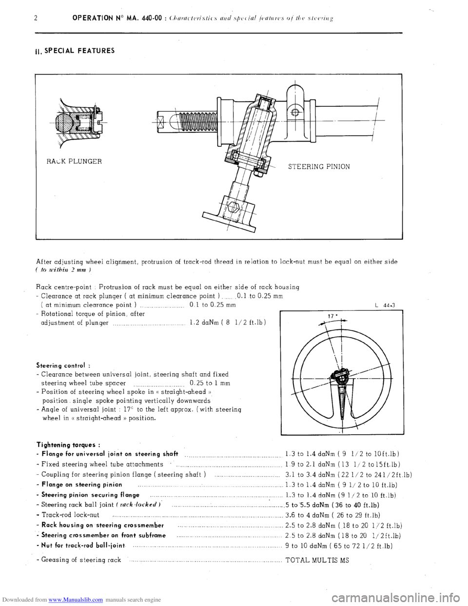
Downloaded from www.Manualslib.com manuals search engine ll, SPECIAL FEATURES
STEERING PINION
After adjusting wheel alignment, protrusion of track-rod thread in relation to lock-nut must be equal on either side
( .to within 2 mm )
Rack centre-point Protrusion of rack must be equal on either side of rack housing
- Clearance at rack plunger ( at minimum clearance point ) .O.l to 0.25
( at minimum clearance point ) ., .,...._...... .._._ 0 1 to 0.25 mm
- Rotational torque of pinion, after
adjustment of plunger .._..... .._.... 1.2 daNm ( 8 l/2 ft.lb)
L 44.3
Steering control :
- Clearance between universal joint, steering shaft and fixed
steering wheel tube spacer 0.25 to 1 mm
.._....__._..._.... ._..__..
- Position of steering wheel spoke in (( straight-ahead ))
position. single spoke pointing vertically downwards
- Angle of universal joint : 17” to the left approx. (with steering
wheel in (( straight-ahead )) position.
- Coupling for steering pinion flange ( steering shaft ) ....................................
- Flange on steering pinion ................................................................................
- Steering pinion securing flange ........................................................................
- Steering rack ball joint f rack Jacked )’ .............................................................
- Track-rod lock-nut ..............................................................................................
- Rack housing on steering crossmember ..........................................................
-. Steering crossmember on front subframe ..........................................................
- Nut for track-rod ball-joint ................. ................................... ..... ...................... Tightening torques :
- Flange for universal joint on steering shaft __..._.__.._._.........,.........................,. 1.3 to 1.4 daNm ( 9 11 2 to
lOft.lb)
- Fixed steering wheel tube attachments
. . . . . . . . . . . . . . . . . . . . . 1 9 to 2.1 daNm (13 l/2 to15ft.lb)
3.1 to 3.4 daNm (22 l/2 to 241/2ft,lb)
1.3 to 1.4 daNm ( 9 l/ 2 to 10 ft.lb)
1.3 to 1.4 daNm (9 l/2 to 10 ft.lb)
.5 to’5.5 daNm (36 to 40 ft.lb)
3.6 to 4 daNm ( 26 to 29 ft.lb)
2.5 to 2.8 daNm ( 18 to 20 l/2 ft.lb)
2.5 to 2.8 daNm (18 to 20 1/2ft.lb)
9 to 10 daNm ( 65 to 72 l/2 ft.lb)
- Greasing of steering rack TOTAL MULTIS MS
Page 300 of 394

Downloaded from www.Manualslib.com manuals search engine OPERATION N” MA. 510-00 a : Arrnr~g(,v~ ('I, I 0 / Ih CJ c~lvclric-cil irtslnllc7liori Op. MA. 510-00 a 3
(I.‘1975 -7 1975 J
-
den{
lark
i
6
8
9
0
1
2
3
4
5
6
7
8
9
!l
!2
!3
!4
!5
!6
!7
!8
$0
)l
12
33
34
35
36
37
38
39
41
42
43
44
45
46
47
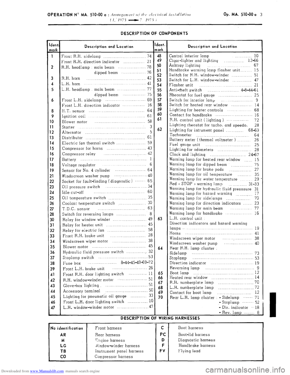
- DESCRIPTION OF COMPONENTS
Description and Location
‘ront R.H. sidelamp ................................... 74
‘rant R.H. direction indicator .................. 21
1.H. headlamp main beam ................. ..... 78
dipped beam ... .................. 76
3.H. horn 42 .............................................
,.H. horn ....................... ............. ............. 41
,.H. headlamp main beam .......................
77
dipped beam .................... 75
‘rant L.H. sidelamp .........
........................
69
:ront L.H. direction indicator .................. 16
I.T. sensor ............................................ 64
qnition coil ..............................................
61
3lower
motor .........................................
58
;tarter ...................................................... 3
Alternator ..................................................... 5
Xstributor 61 ...................................................
7lectric fan thermal switch .........................
59
Zompressor for horns ................................. 43
Compressor relay ..... .................
.............. 42
3attery ........... ...............................................
1
Joltaqe regulator ....................... ............. 6
jacket for fault-finding ( diagnosfic) ....... 65
3il pressure switch .... ....................... ... 34
:dle cut-off ........................................... 60
3il temperature switch
35 .............................
Coolant temperature switch ....................... 30
T.D.C. sensor ......................................... 63
Switch for reversing lamps .......................... 8
Relay for window winder ............................. 49
Relay for heater unit 45
................... ..............
Relay for electric fan 58 ..................................
Front R.H. brake unit 28 ...............................
Windscreen wiper motor .............................. 38
Blower motor ................................................ 45
Hydraulic fluid pressure switch ................... 32
Stoplamp switch ........................................... 53
Fuse box ..... .................... 8-44-45-49-69-72
Front L.H. brake unit ........................... ... 26
Front R.H. door lighting switch ... ............
11
R.H. window-winder motor .......................... 51
Glove-box lighting ....................................... 51
Accessory terminal ......................................
5c
Lighting for pneumatic oil gauge .............. 3:
Front L.H. door lighting switch
.................. I[ L.H .
window-winder motor ........................... .47 DESCRIPTION C
No identification
AR
M
LG
TB
co
Front harness
Rear harness
Ynqine harness
dindow-winder harness
Instrument panel harness
Compressor harness jent.
/ark
4”9 50
51
52
53
54
55
56
57
58
59
60
61
62
63
64
iz
67
68
69
70 Description and Location Central interior lamp ............ 10
Cigar-liqhter and lighting
.............. 13-66
Ashtray liqhtinq ...................................
67
Handbrake warning lamp flasher unit
........ 15
Switch for R.H. window-winder
.............. 51
Switch for L.H. window-winder ................ 47
Flasher unit .............................................. 21
Anti-theft switch ......................... 4-8-44-61
Rheostat for fuel qauqe ............................ 25
Switch for interior lamp ... ....................
9
Switch for heated rear window ...................
14
Liqhting for heater controls ..................... 68
Contact for handbrake
............................... 115
R.H. control unit ( liqhtinq )
................... 72
Lighting rheostat for tacho. and speedo.
28
Lighting for intrument panel ................ 68-69
Tachometer
............................................ 64
Battery meter (thermal voltmeter )
.......... 26
Fuel gauge unit
..... ....... ....... ................ 25
Lighting for odometers
....... ......... .......... 28
Clock and lighting ................................ 24-67
Warning lamp for heated rear window
15 .......
Warning lamp for dipped beam 75
_, .................
Warninq lamp for brake pads ................... 27
Warninq lamp for oil temperature
............ 35
Warning lamp for water temperature
.......... 29
Red u STOP 1) warninq lamp
............... 31-33
Warninq lamp for hydraulic fluid presssure 31
Warninq lamp for hazard warning
17
...............
Warninq lamp for sidelamps .................... 70
Warning lamp for direction indicators ...... 23
Warninq lamp for main beam ................. 77
Warning lamp for handbrake
..................... 16
L.H. control unit
Direction indicators and hazard warning lamps .........................................................
19
Horns .......................................................... 41
Windscreen wiper motor ....... .................. 38
Windscreen washer pump .......................... 40
Rear R.H. lamp cluster
Sidelamp ...................................................
73
Stoplamp ....................... .............................. 53
Direction indicator ......................................
19
Reversing lamp ....................... .............
9
Boot lamp ................................................... I2
Heated rear window 14 .....................................
R.H. numberplate lamp ...............................
70
L.H. numberplate lamp ...........
.................... 72
Contact for boot lamp .............................
12
Rear L.H. lamp cluster - Sidelamp
........ 71
,- Stoplamp
.......... 52
- Dir. indicator .. 18
- Rev. lamp ......... 8
IG HARNESSES
Boot harness
Boot-lid harness
Diagnostic harness
Handbrake harness
Flying lead