Indicator Citroen CX 1979 1.G Owner's Manual
[x] Cancel search | Manufacturer: CITROEN, Model Year: 1979, Model line: CX, Model: Citroen CX 1979 1.GPages: 394
Page 341 of 394

Downloaded from www.Manualslib.com manuals search engine dent,
nark
B9
90
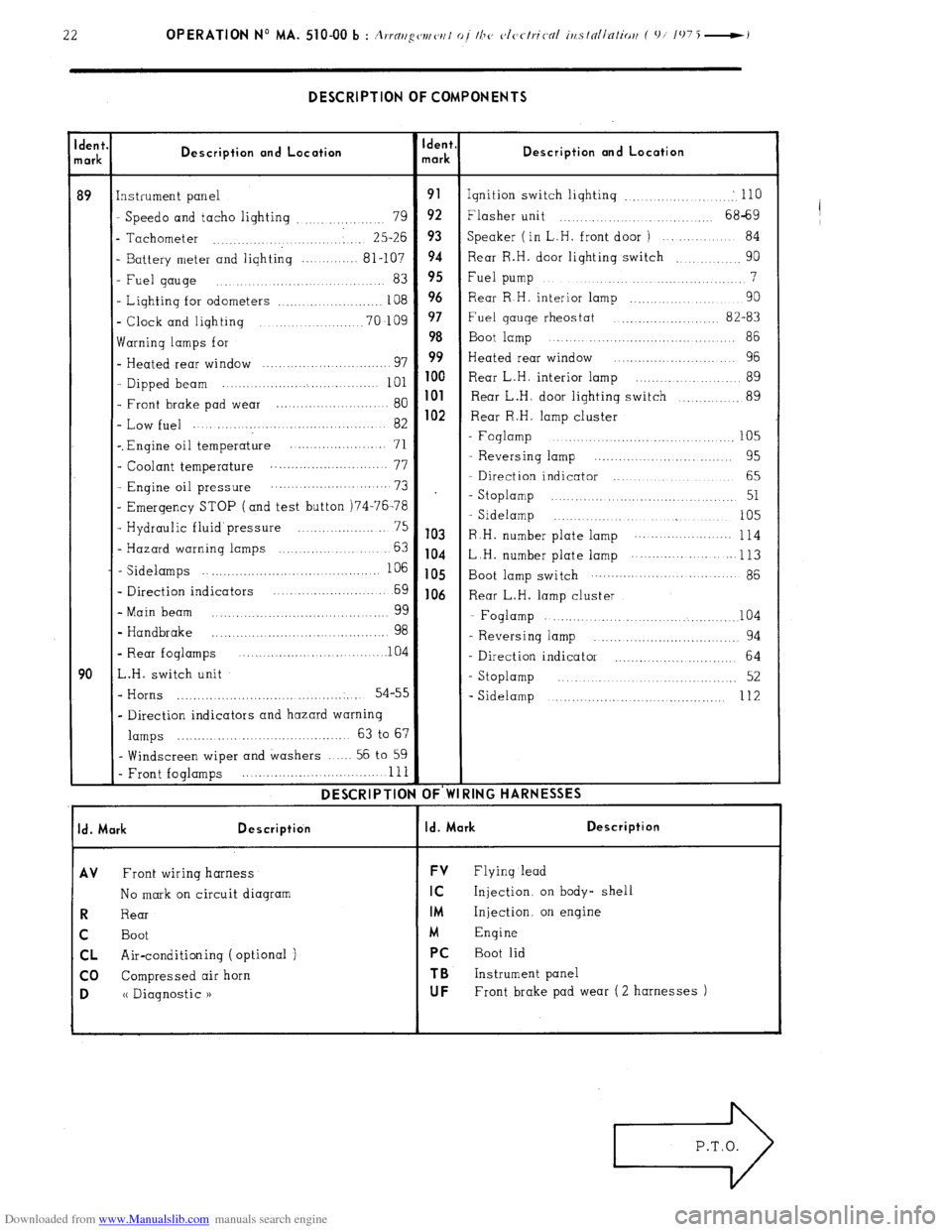
DESCRIPTION OF COMPONENTS
Description and Location
instrument panel
Speed0 and tacho lighting
79 ..............
. Tachometer 25-26
........... ............
I Battery meter and lighting ............ 81-107
Fuel gauge ...................... 83
- Lighting for odometers
...................... 108
- Clock and lighting
.................... 70-109
warning lamps for
- Heated rear window ............................... 97
- Dipped beam ... ..... ............................ 101
- Front brake pad wear ...................... 80
- Low fuel ....
............................ 82
-. Engine oil temperature ..... .................
71
- Coolant temperature ...........................
77
- Engine oil pressure ....... .... ............ ...
73
- Emergency STOP (and test button )74-76-78
- Hydraulic fluid’pressure ................... 75
- Hazard warning lamps ....................... 63
- Sidelamps 106
....................... ..... ..............
- Direction indicators ....... ............... 69
- Main beam
99 .....
.............................. ...
- Handbrake
98 ........ ............ ., .............. ...
- Rear foglamps .......... ................. ..lO 4
L.H. switch unit
- Horns 54-55
..... ....................................
- Direction indicators and hazard warning
lamps ...................................... 63 to 67
- Windscreen wiper and washers ...... 56 to 59
- Front foglamps ........ ....... ................. 111
DESCRIPTIOI dent
nark
91
92
93
94
95
96
97
98
99
100
101
102
103
104
105
106 Description and Location
Ignition switch lighting .................... : 110
Flasher unit ....................... 68-69
Speaker ( in L..H. front door )
......... 84
Rear R.H. door lighting switch
90 ..........
Fuel pump 7
.............................
Rear R H. interior lamp ....................
90
Fuel qauge rheostat
.................... 82-83
Boot lamp
....................................... 86
Heated rear window
......................... 96
Rear L.H. interior lamp
.................. 89
Rear L.H. door lighting switch
............ 89
Rear R.H. lamp cluster
- Foglamp
..................................... 105
- Reversing lamp .............................
95
- Direction indicator ...................
65
- Stoplamp ........... ......................... 51
- Sidelamp ...........................
105
R .H. number plate lamp .......... ... ........
114
L H. number plate lamp ..... ........... ...
113 Boot lamp switch .................................
86
Rear L.H. lamp cluster
- Foglamp
....................................... 104
- Reversing lamp ................................
94
- Direction indicator ............................. 64
- Stoplamp
........................................ 52
- Sidelamp
... ..... ................................. 112
IING HARNESSES
I Id. Mark Description
I Id. Mark Description
AV
Front wiring harness FV Flying lead
No mark on circuit diaqram
IC Injection. on body- shell
R Rear IM Injection, on engine
C Boot
M Engine
CL Air-conditioning (optional ) PC Boot lid
co Compressed air horn
TB Instrument panel
D (( Diagnostic 1) UF Front brake pad wear ( 2 harnesses )
Page 362 of 394

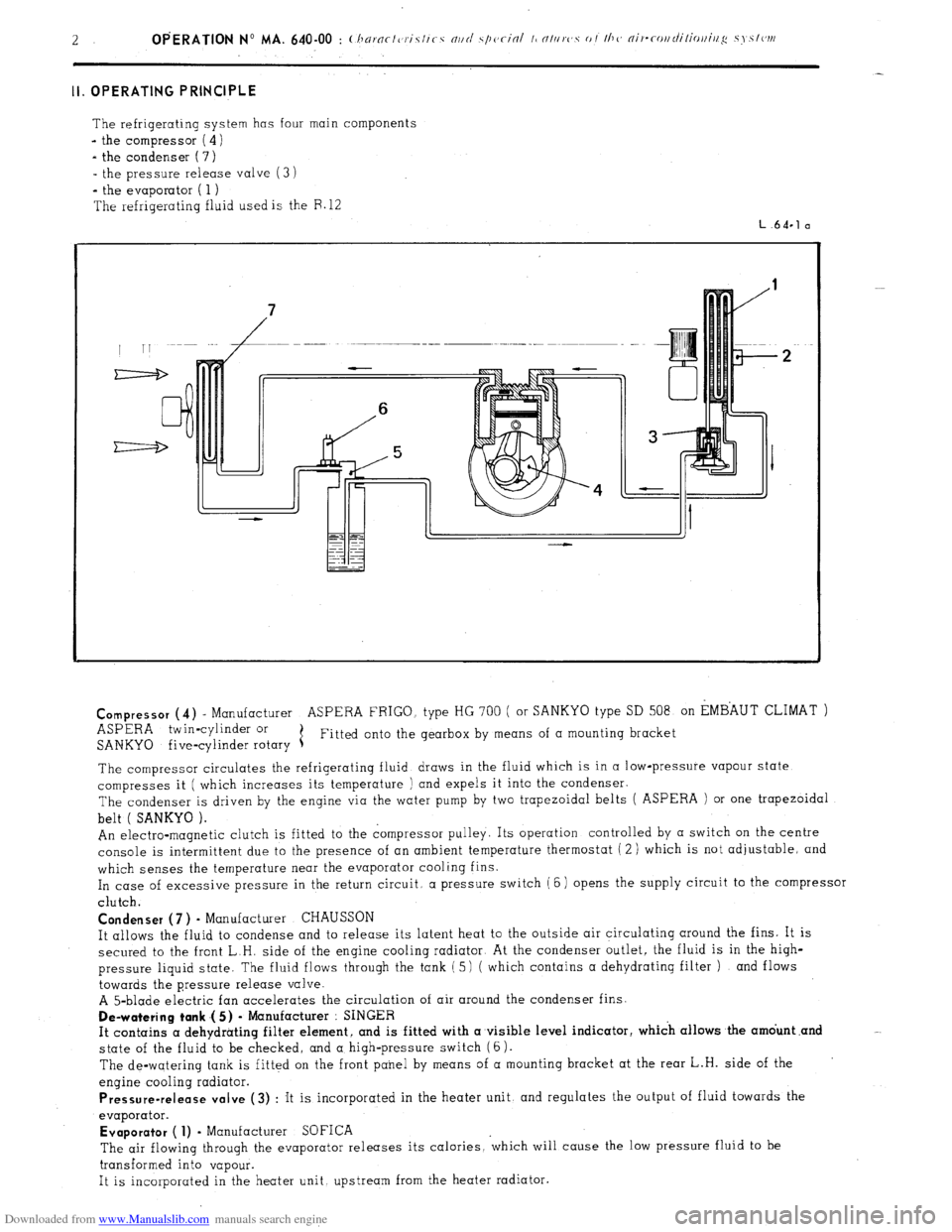
Downloaded from www.Manualslib.com manuals search engine II. OPERATING PRINCIPLE
The refrigerating system has four main components
- the compressor ( 4)
- the condenser ( 7)
- the pressure release valve (3 i
*
the evaporator ( 1 )
The refrigerating fluid used is the F. 12
L.64.1 a
Compressor
(4) - Manufacturer ASPERA FRIGO. type HG 700 ( or SANKYO type SD 508 on EMBAUT CLIMAT )
ASPERA twin-cylinder or
SANKYO five-cylinder rotary 1 Fitted onto the gearbox by means of a mounting bracket
The compressor circulates the refrigerating fluid draws in the fluid which is in a low-pressure vapour state
compresses it ( which increases its temperature ) and expels it into the condenser.
The condenser is driven by the engine via the water pump by two trapezoidal belts ( ASPERA ) or one trapezoidal
belt ( SANKYO ).
An electro-magnetic clutch is fitted to the compressor pulley. Its operation controlled by a switch on the centre
console is intermittent due to the presence of an ambient temperature thermostat ( 2 ) which is not adjustable, and
which senses the temperature near the evaporator cooling fins.
In case of excessive pressure in the return circuit, a pressure switch (6) opens the supply circuit to the compressor
clutch.
Condenser (7 ) - Manufacturer CHAUSSON
It allows the fluid to condense and to release its latent heat to the outside air circulating around the fins. It is
secured to the front L.H. side of the engine cooling radiator At the condenser outlet, the fluid is in the high-
pressure liquid state. The fluid flows through the tank ( 5) ( which contains a dehydrating filter ) and flows
towards the pressure release valve.
A 5-blade electric fan accelerates the circulation of air around the condenser fins.
De-watering tank .( 5) - Manufacturer : SINGER
It contains a dehydrating filter element, and is fitted with a visible level indicator, which allows the amdunt .and
state of the fluid to be checked, and a high-pressure switch (6).
The de-watering tank is fitted on the front panel by means of a mounting bracket at the rear L.H. side of the
engine cooling radiator.
Pressure-release valve (3) : It is incorporated in the heater unit, and regulates the output of fluid towards the
evaporator.
Evaporator ( 1) - Manufacturer SOFICA
The air flowing through the evaporator releases its calories, ‘which will cause the low pressure fluid to be
transformed into vapour.
It is incorporated in the heater unit upstream from the heater radiator.