check oil Citroen CX 1981 1.G User Guide
[x] Cancel search | Manufacturer: CITROEN, Model Year: 1981, Model line: CX, Model: Citroen CX 1981 1.GPages: 394
Page 136 of 394
Downloaded from www.Manualslib.com manuals search engine 5. Air-flow sensor ( DIAGRAM 5 )
- Disconnect the E.C.U.
- Using an ohmmeter check the continuity of circuits (( 6 )a, H 7 )) (( 8 H and (( 9 )) linking the air-flow sensor to
the multiple terminal board. as well as the continuity between each of the terminals
- The air-flow meter does not require any maintenance. It is not necessary to oil the flop. It must work without
high spot or catching
When the air-flow sensor is removed blank off the ducts so OS to protect it from dust
- Check the air circuit for air-tightness.
6. Resistors and injectors :
- A dirty injector may cause o lock of power. or on unstable idling speed.
- It is possible to test the functioning of the injectors with the engine idling by disconnecting each injector
in turn the engine rpm should decrease each time.
- Disconnect the E C U
- The resistance of an injector is 2 to 3 II.
- Each supplementary resistance is 5 to 7 R
- The volume delivered by an injector ( kept constantly open and under the normal operating pressure ) is
approximately 200 cm3 /min ( 12 25 cu in/min )-
- If the rubber pipe on one of the injectors appears wet on the outside, the injector must be replaced.
- Using an ohmmeter, check the continuity of the circuits
Page 149 of 394
Downloaded from www.Manualslib.com manuals search engine 28 OPERATION N” MA.IE. 144-O : Ch <,c ,ng n,,d nlfjusfiup Ihe u I.-~<~tro,,ir i) <~lrr/mr,ir k’
/,,,.I i,,jrr/io,, S~S,W1, ANNEXE : D - ADJUSTING THE IDLING SPEED AND THE EXHAUST EMISSION
CHECKING CONDITIONS
1.
Checking the idling speed must be carried out
on a clean engine on which the ignition and the
valve clearances are properly adjusted and
fitted with a clean air-filter.
2. Check that the throttle butterfly returns correctly
to its stop.
3. Do not load the alternator by switching an any
of the electrical components, except the iqnition
and the electric cooling fan (s) 4.
Run the engine to bring the oil temperature up
to 70 +o 80’ C ( wait for the electric cooling
fan is) to cut in ). IMPORTANT : Use exclusively (I high tension
tachometer ( do not damage the H.T. lead of
the ignition wiring harness ).
ADJUSTMENT
1. Check that the butterfly is not jammed in position
when it is resting against its stop.
2. Wait for the electric cooling fan (s) to cut in.
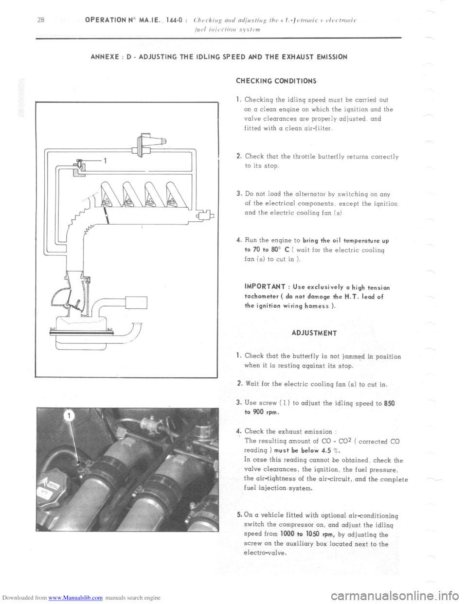
3. Use screw ( 1 ) to adjust the idling speed to 850
to 900 rpm.
4. Check the exhaust emission :
The resulting amount of CO - CO2 ( corrected CO
reading 1 must be beI& 4.5 %.
In case this reading cannot be obtained, check the
valve clearances, the ignition, the fuel pressure,
the air-tightness of the aircircuit, and the complete
fuel injection system.
5. On (I vehicle fitted with optional oirtonditioning
switch the compressor on, and adjust the idling
speed from 1000 to 1050
rpm, by adjusting the
screw on the auxiliary box located next to the
electro-vol”e.
Page 160 of 394
Downloaded from www.Manualslib.com manuals search engine OPERATION No MA. 210.0 : c l~vritis,e nvrl
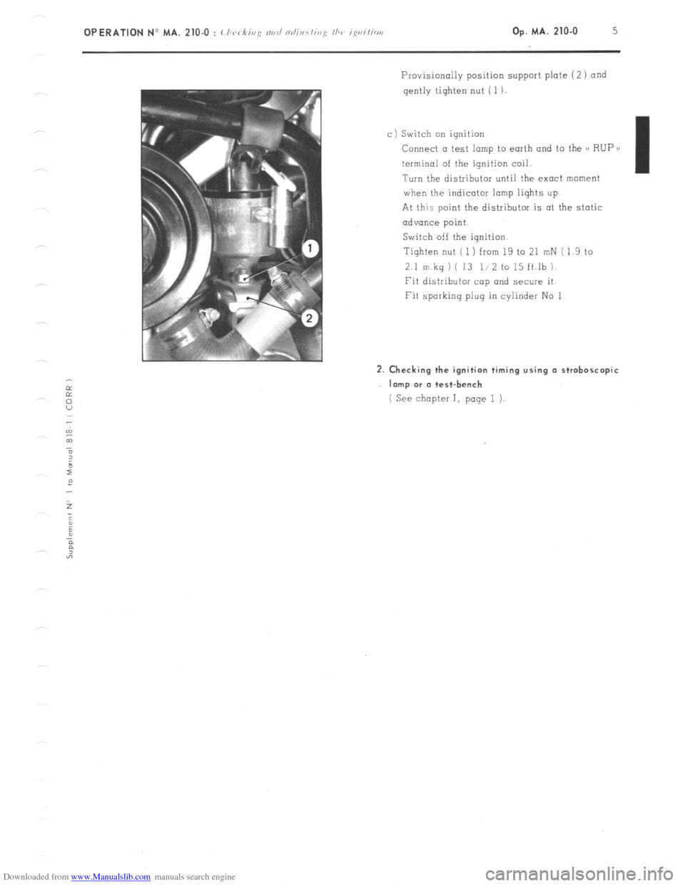
Provisionally position support plate (2 1 and
gently tighten nut ( 1 )
c) Switch on ignition
Connect a test lamp to earth and to the G RUP B)
terminal of the ignition coil.
Turn the distributor until the exact moment
when the indicator lamp liqhts up.
At this point the distributor is al the static
advance point.
Switch off the ignition.
Tighten nut ( 1 ) from 19 to 21 mN ( 1.9 to
2.1 m kq 1 ( 13 l/2 to 15 ft.lb 1.
Fit distributor cap and secure it
Fit sparking plug in cylinder No 1 2. Checking the ignition timing using a stroboscopic
Imp or (I test-bench
( See chapter I,, page 1 i.
Page 165 of 394
Downloaded from www.Manualslib.com manuals search engine OPERATION No MA. 220-O : (.hrrkinfi Ih e oil pr~ssrrrc m the rehicle Op. MA. 220.0 1
CHECKING THE OIL PRESSURE ON THE VEHICLE
79-T 1. Remove spare
wheel.
2. Check oil level if necessary.
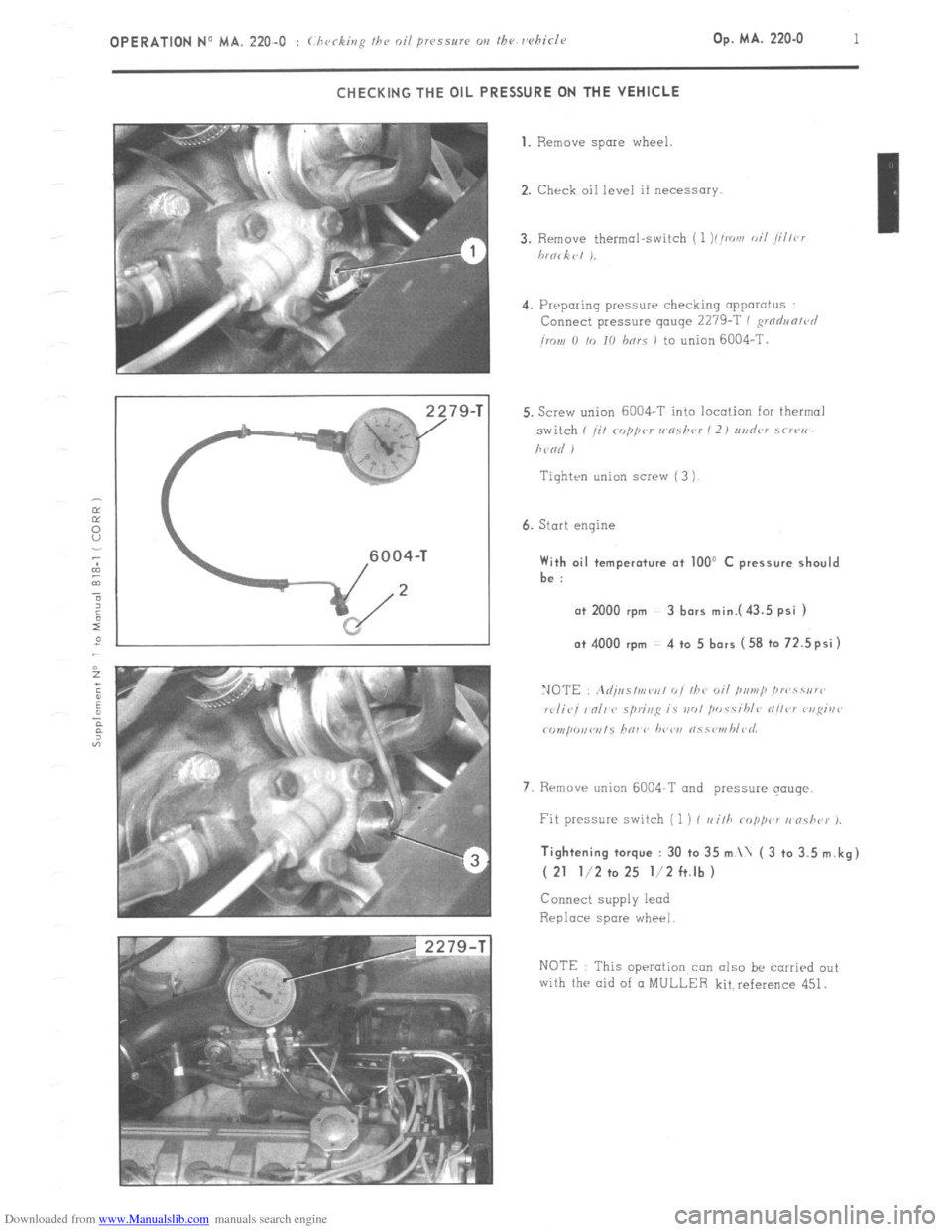
4. Preparing pressure checking apparatus
Connect pressure gauge 2279-T ( ,wdun/r~l
imn 0 /o IO hnrs 1 to union 6004-T.
Tiqhten union screw ( 3 )
6. Start engine With oil temperature at 100’ C pressure should
be :
a+ 2000 rpm 3 bars mini43.5 psi ) o+ 4000 rpm 4 to 5 bars (58 to 72.5psi)
7. Rrmave union 6004-T and pressure qouqe. Tightening torque : 30 to 35 m \ ( 3 to 3.5 m.kg)
( 21 l/2 to 25 l/2 ft.lb )
Connect supply lead
Replace spare wheel
NOTE This operation con also be carried out
with the aid of CI MULLER kit,reference 451.
Page 166 of 394
Downloaded from www.Manualslib.com manuals search engine Op. MA. 221-O I
FILLING AND ADJUSTING THE PNEUMATIC OIL GAUGE
A _ FILLING
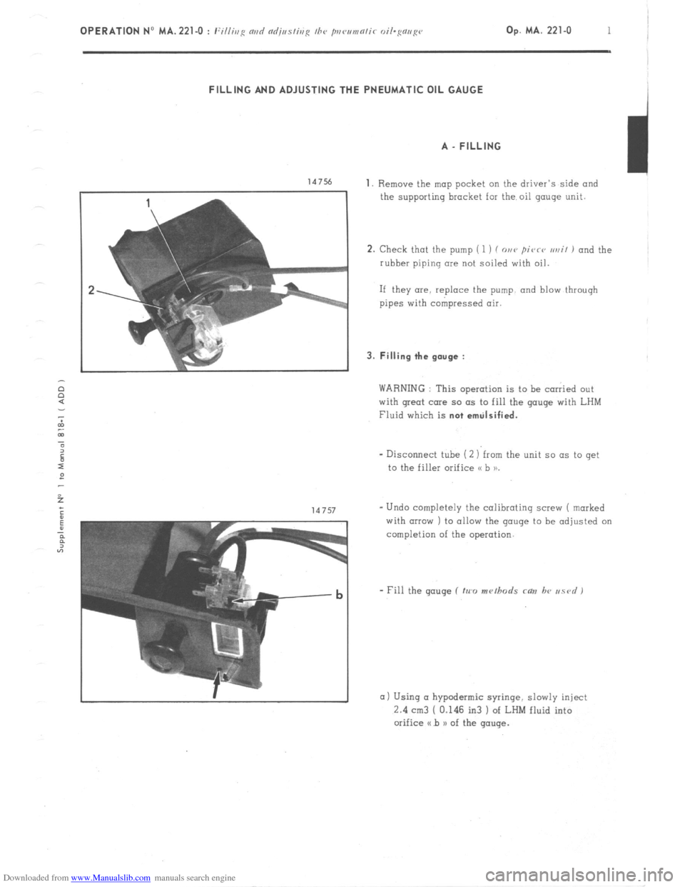
147% 1. Remove the map pocket on the driver’s side and
the supporting bracket for the oil gauge unit.
2. Check that the pump ( 1 ) f o,,v pivrv ur,il 1 and the
rubber piping clue not soiled with oil.
If they are. replace the pump. and blow through
pipes with compressed air. 3. Filling the gauge :
WARNING : This operation is to be carried out
with great care so as to fill the gauge with LHM
Fluid which is not emtilsified.
- Disconnect tube (2 ) from the unit so as to get
to the filler orifice o b 11.
- Undo completely the calibrating screw ( marked
with (IIPXJ ) to allow the gauge to be adjusted on
completion of the operation.
a) Using CI hypodermic syringe. slowly inject
2.4 cm3 [ 0.146 in3 ) of LHM fluid into
orifice a b n of the gauge.
Page 168 of 394
Downloaded from www.Manualslib.com manuals search engine Op. MA. 221-O 3 -
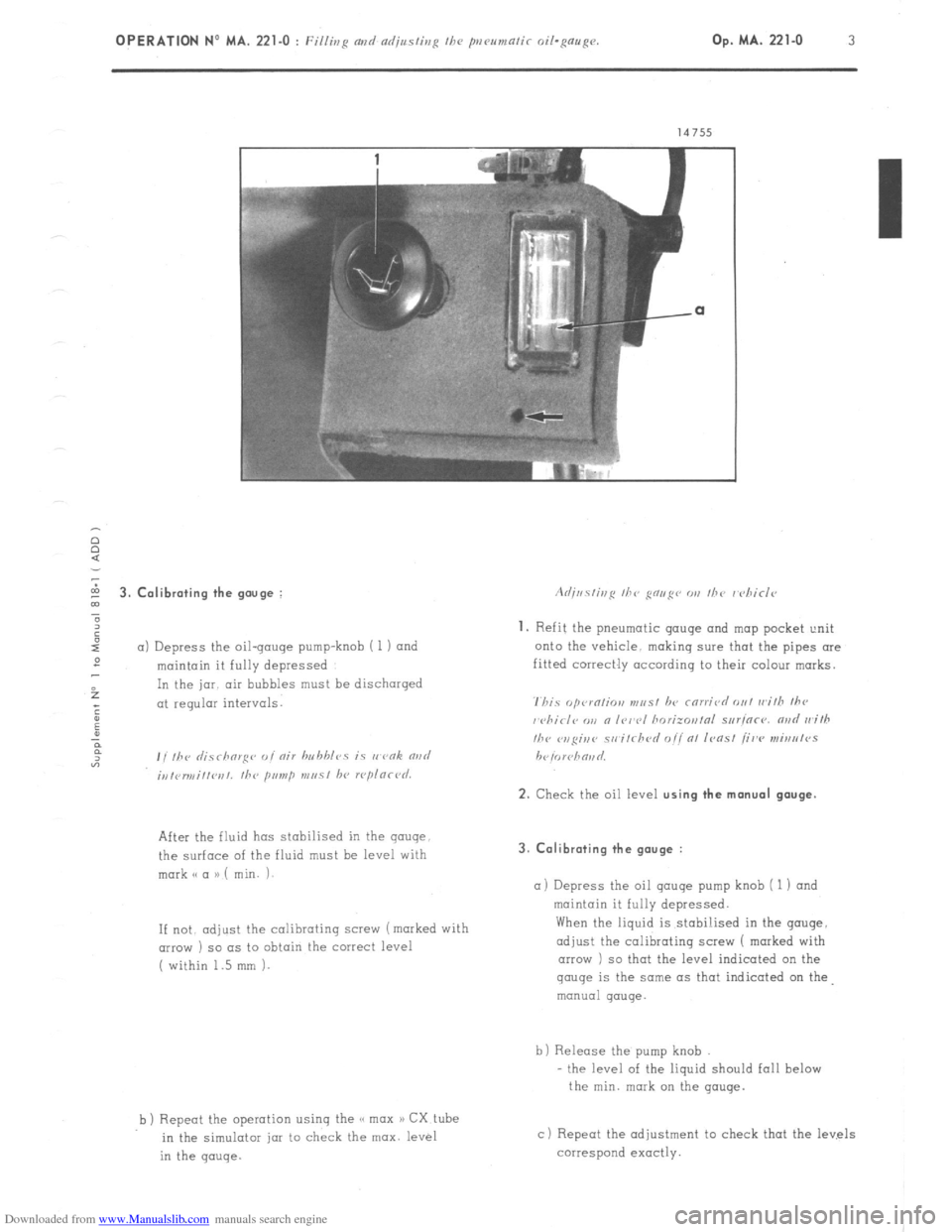
5 3. Calibrating the gouge :
”
6
I
a) Depress the oil-gouge pump-knob i 1) and
:
maintain it fully depressed
f In the jar. air bubbles must be discharged
; at regular intervals.
:
u
P
F
“3 , , ,hr ,I;.7 rhorg<~ ,, I nir hn hhlcs is I, vnk rind
;,,,<,r,,,i,,l~r,,. the primp m,, 51 hl, rcplnrl~d.
After the fluid has stabilised in the gauge
the surface of the fluid must be level with
mark o a a) ( min. i-
If not. adjust
the calibrating screw (marked with
(IIIOW ) so as to obtain the correct level
( within 1.5 mm 1.
b ) Repeot the operation using the << max a) CX tube
in the simulotar jar to check the max. level
in the gauge. 3. Calibrating the gauge :
a) Depress
the oil qauqe pump knob ( 1 1 and
maintain it fully depressed.
When the liquid is stabi!ised in the gouge,
adjust the calibrating screw 1 marked with
arrow ) so that the level indicated on the gauge
is the same as that indicated on the
manual gauge.
b) Release the pump knob
- the level of the liquid should fall below
the min. mark on the gauge.
c) Repeat the adjustment to check that the levels
correspond exactly.
Page 228 of 394
Downloaded from www.Manualslib.com manuals search engine 2 OPERATION No MA. 390-O : Checking the hydra&c conponmts on the.uehicle
f Mnnual sirrrin~ uehicles J CHECKS
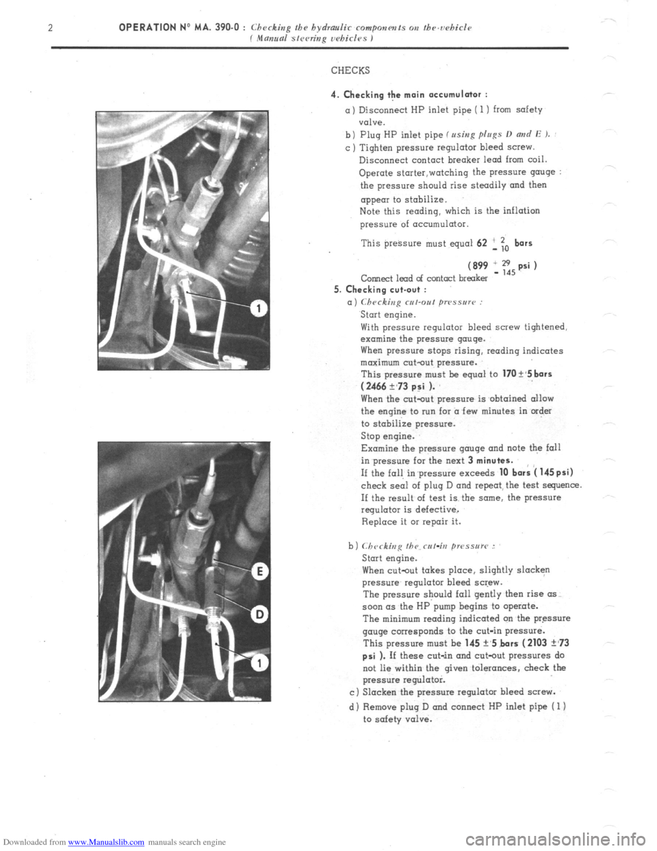
4. Checking the main accumulator : a) Disconnect HP inlet pipe ( 1) from safety
valve.
b) Plug HP inlet pipe fusing p[u~s D
and E ). : c ) Tighten pressure regulator bleed screw.
Disconnect contact breaker lead from coil.
Operate storter,watching the pressure g”“ge :
the pressure should rise steadily and then
appear to stobilize.
Note this reading, which is the inflation
pressure of acc”mulator.
This preksure must equal 62 ‘, To
bars
(899 IE,psi) Corned lead of contact breaker
5. Checking cut-out :
a) Checking cut-out ~TPSSU~~~ : Start engine.
With pressure regulator bleed screw tightened,
examine the pressure gauge.
When pressure stops rising, reading indicates
maximum cut-out pressure.
This pressure m”st be equal to
170 t’5 bars
(2466 ?,73 p:i ). When the c”t-o”t pressure is obtained allow
the engine to nrn for a few minutes in order
to stabilize pressure.
Stop engine.
Examine the pressure gauge and note the fall
in pressure for the next 3
minutes. If the fall in’pressure exceeds
10 bark 4 145psi) check seai of plug D and repeat, the test sequence.
If the result of test is the some, the pressure
regulator is defective,
Replace it 01 repair it.
When cutout takes place, slightly slacken
pressure regulator bleed screw.
The pressure should fall gently then rise (IS~.
soon (IS the HP pump begins to operate.
The minimum reading indicated on tbe pressure
gauge corresponds to the cut-in pressure.
This pressure must be 145 +,5 bars
(2103 ?,73
psi ). If these cut-in and cot-out pressures do
not lie within the given tolerances, check the
pressure regulator.
c) Slacken the pressure regulator bleed screw.
d) Remove plug D and connect HP inlet pipe ( 1)
to safety valve.
Page 229 of 394
Downloaded from www.Manualslib.com manuals search engine OPERATION No MA. 390-O : Checkin
P the hydraulic componm~s on the ucbicle Op. MA. 390-O 3
f Mama sleeting wbi&s I
6. Checking the safety valve :
=I
bl
Cl
dl
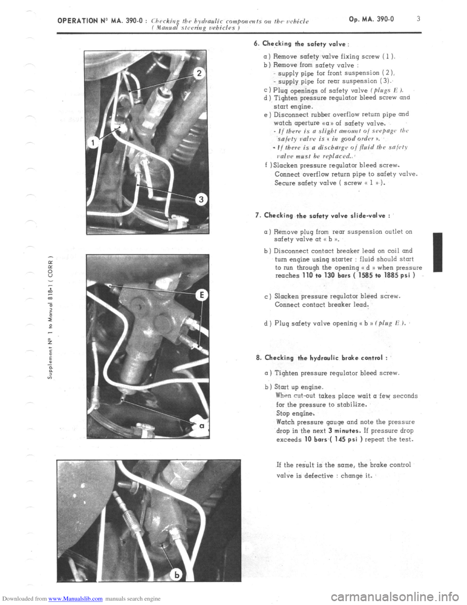
Remove safety v&e fixing screw ( 1 ).
Remove from safety valve :
supply pipe for front suspension (2 ),
- supply pipe for rem suspension (3):
Plug openings of safety valve ( pIugs E J.
Tighten pressure regulator bleed screw
and
start engine.
Disconnect rubher overflow return pipe and
watch aperture ~a>> of safety valve.
- I/ Iherr is a slight c7moa,,t 0, sHymge thr
sa/cty ~dve is s in good ordrv n.
el
-If thrr~ is a discharge of fluid the sniw
dw must be rqlacrd..
f ) Slacken pressure regulator bleed screw-
Conned overflow return pipe to safety valve.
Secure safety valve ( screw (( 1 a) 1.
7. Checking the safety valve slidevolve :
a) Remove plug from rem suspension outlet on
safety v&e at G b >a.
b ) Disconnect contact breaker lead on coil and
turn engine using stmter : fluid should start
to run through the opening a d N when pressure
reaches
1lLl +o 130 bars ( 1585 to 1885 psi )
c) Slacken pressure regulator bleed screw.
Connect contact breaker lead.
d ) Plug safety valve opening u b )) (plug E ).
8. Checking the hydraulic brake contml :
m ) Tighten pressure regulator bleed screw.
b) Start up engine.
When cut-out takes place wait a fen: seconds
for the pressure to stobilize.
Stop engine%
Watch pressure gauge and note the pressure
drop in the next 3
minutes. If pressure drop
exceeds 10 bors*( 145 psi ) repeat the test.
If the re< is the same. the broke control
valve is defective : change it.
Page 243 of 394
Downloaded from www.Manualslib.com manuals search engine a OPERATION N’ MA. 410-O : (./~rrkiq N,,I/
VI. CHECKING AND ADJUSTING THE STEERING GEOMETRY
The crossmember supporting the steering has slots at its fixing point on the front subframe.
Any vertical movement of this crossmember alters the steering geometry.
WARNING
This operation is only to
be carried out in certain ccxses such as
-accidental impact, with repercussions on the steering system.
-work on the vehicle entoiling removal of steering crossmember.
- vehicle with poor
road stability ( p oar stright-line stability) 01 with excessive tyre weor.
CHECKING
1, Prepare the vehicle. as for checking front wheel
alignment ( Srr ~ho/,lvr
V I.
NOTE
A ) \In,,unl ~fi~<,r;,,~ I chiclvs :
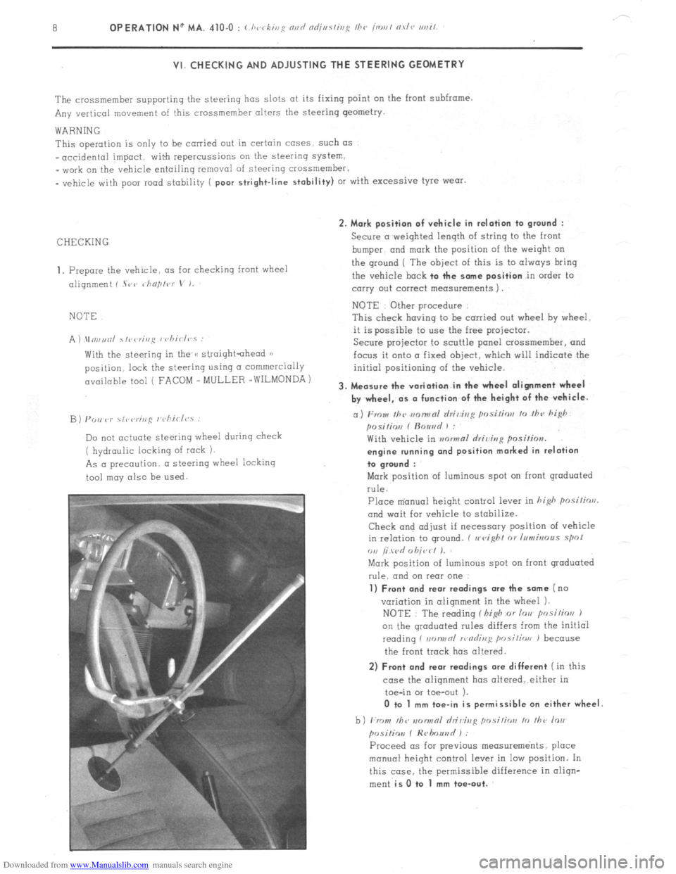
With the steering in the /< straightahead 1)
position. lock the steering using CI commercially
available tool ( FACOM _ MULLER -WILMONDA)
B) PO,, P)’ \,r,rr;ng r’cliirl<,.s :
Do not actuate steering wheel during check
( hydraulic locking of rock 1.
As a precaution. a steering wheel iocking
tool may also be
used. 2. Mark position of vehicle in relation to
ground :
Secure a weighted length of string to the front
bumper. and
mark the position of the weiqht on
the ground ( The
object of this is to always bring
the vehicle
bock to the some position in order to
carry out correct measurements 1.
NOTE Other procedure
This check having to be carried out wheel hy wheel.
it is possible to use the free projector.
Secure projector to scuttle panel crossmemher, and
focus it onto a fixed object, which will indicate the
initial positioning of the vehicle.
3. Measure the variation in the wheel alignment wheel
by wheel, ds o function of the height of the vehicle.
a) From Ihc m~nwnl rlri,:ir,g posi/ior, lo /hc hi@
posilio,, f ftouad 1 :
With vehicle in mwmal rlriving position.
engine running ond position marked in relation
to groond :
Mark position of luminous spot on front graduated
rule.
Place m’anual height control lever in hi&
posilirrrl.
and wait for vehicle to stabilize.
Check and adjust if necessary position of vehicle
in relation to ground. ( II
eight 01 Inmbrous spol
ou /i wd 0 hit,< I J.
Mark position of luminous spot on front graduated
rule. and on rear one
1) Front and rear readings ore the some (no
variation in alignment in the wheel 1.
NOTE : The reading f I,i$ or lorr posilios J
on the qroduated rules differs from the initial
reading f non,,nl >r,nrlinl:
position J because
the front track has altered.
2) Front and rear readings ore different ( in this
case the alignment has oltered,.either in
toe-in or toe-out ).
0 to 1 mm toe-in is permissible on either wheel
b) ,:rr ,,I, /bv IIDIINRI hi&g ,,osi,;orr lo ,I,<, lo,,
posiliov f Hrlmuad ) :
Proceed OS for previous measurements, place
manual height control lever in low position. In
this case. the permissible difference in oliqn-
ment
is O.to 1 mm toe-out.
Page 359 of 394
Downloaded from www.Manualslib.com manuals search engine OPERATION No MA. 560.0 : ~hrrkin~ o,,d oc/@s/i,,g I/><, wiurisrrrr,, wip’r. Op. MA. 560.0
1
Fi
m
0 CHECKING AND ADJUSTING THE WINDSCREEN WIPER.
FRONT WINDSCREEN WIPER MOTOR
CHARACTERISTICS.
Manufacturer DUCELLIER
Reference No. 4966 A
Field coils Ferrite
Armature : Endfloot (adjustable by means of stop-screw) : 0.2 mm
Nominal dia. of commutator :
24 mm
Min. dia. after machining : 23 mm
Brushes : Ref. No. :
CL 7239
Minimum length after wear : 5.5 mm
Ratio : .._...................................................................................................
44 1
Connection and circuit diagram as in Op. MA. 510 00.
ELECTRICAL CHECK. BOSCH
0390 346 127
Ferrite
0
23.2 mm
23 mm
1.394.320-058 059, 062
7.5 mm
49 1
1. First speed :
Nominal power : IO watts
Speed, under no load, at 13.5 volts = 50 rpm Corresponding current = I.8 A
Torque, motor locked, at 13.5 volts = 1.9 da Nm 7 13.74 ft.lb min. Corresponding current 18 A max.
Torque at 40 rpm and 13.5 volts = 0.2 do Nm (1.45 ft.lb) Correspondinq current = 5.5 A max.
- Torque ot 20 rpm and 13.5 volts = 1.07 da Nm (7.74 ft.lb) min Corresponding current = 13.2 A max.
2. Second speed :
Nominal power : 15 watts
Speed under no load at 13.5 volts = 70 rpm Corresponding current = 2.3 A
Torque motor locked at 13.5 volts = 1.5 do Nm (IO.85 ft.lb) min Corresponding current = 21 A max
Torque at 60 rpm and 13.5 volts = 0.2 da Nm (1.45 ft.lb) min Corresponding current = 7 A max
Torque ot 30 rpm and 13.5 volts = 0.9 da Nm (6.51 ft.lb) min Corresponding current = 14.7 A mrx.
ADJUSTMENT OF WINDSCREEN WIPER ARM
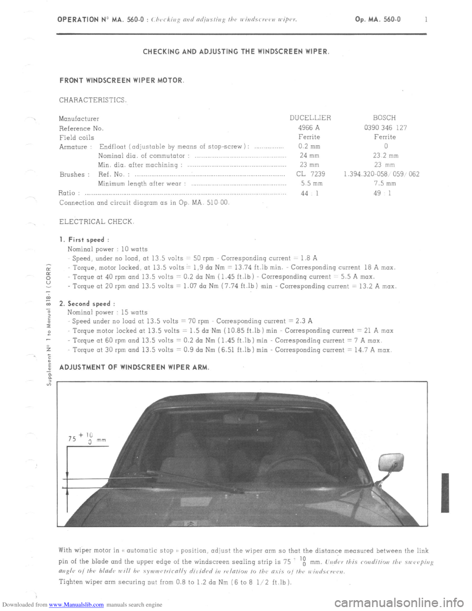
With wiper motor in (< automatic stop )/ position, adjust the wiper arm so that the distance measured between the link
pin of the blade and the upper edge of the windscreen sealing strip is 75 ‘t
mm. L’vd‘ar /his rondiliw, /he 51, rvp;,,g
m,g/r 0, /he bladr ,,~i// hv symv,r~/rirn//v dil idrd it, w/n/io,, 10 /he O.YiS “, I/w r,‘iri
Tighten wiper arm securing out from 0.8 to 1.2 da Nm (6 to 8 l/2 ft.lb).