gearbox Citroen CX 1981 1.G User Guide
[x] Cancel search | Manufacturer: CITROEN, Model Year: 1981, Model line: CX, Model: Citroen CX 1981 1.GPages: 394
Page 20 of 394
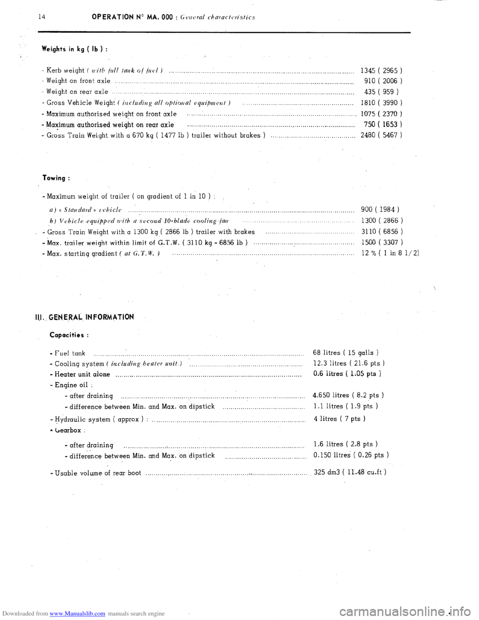
Downloaded from www.Manualslib.com manuals search engine 14 OPERATION No MA. 000 : G<,ncraZ charactc,ristics Weights in kg ( lb ) :
- Kerb weight ( with jull Iauk of fill ) ....................... . ............................................................................ 1345 ( 2965 )
- Weight on front axle ........... .................................................................................................................... 910 ( 2006 )
Weight on rear axle ........................................................................................................................ 435 ( 959 )
- Gross Vehicle Weight ( ir~cludiug all mp/inual ~~quipmwt ) ....................................................... 1810 ( 3990 )
- Maximum authorised weight on front axle ................................................................................... .
1075 (2370 )
- Maximum authorised weight on rear axle .................................................. ..~...............~ .............. 750 ( 1653 )
- Gross Train Weight with a 670 kg ( 1477 lb ) trailer without brakes ) ..........................................
2480 ( 5467 ) Towing :
- Maximum weight of trailer ( on gradient of 1 in 10 ) :
a) s StaiJdard )) r,ehiclc ................................................................................................................ 900 ( 1984 )
h) Vchicfe equipped with a second IO-blade cooling jar? ....................................................... 1300 ( 2866 )
- Gross Train Weight with a 1300 kg ( 2866 lb ) trailer with brakes ............................................ 3110 ( 6856 )
- ‘Max. trailer weight within limit of G.T.W. ( 3110 kg - 6856 lb ) .................... . ............................. 1500 ( 3307 )
- Max. starting gradient ( at G. 7‘. W. I) .......................................................................................... 12 % ( 1 in 8 l/2) I1.l.. GENERAL INFORMATION
Copoci;ies :
- Fuel tank .._.___._._._._.’ __.._._._..._....._._._,_..,._.,_..._..,_,._...._,___....___._______.............,.,.... 68 litres ( 15 galls )
- Cooling system ( ilzcluding heater unit,) __...._.___,_.__.....,....._._.___..___._._____..._._._. 12.3 litres ( 21.6 pts )
- Heater unit alone . . . . . . . . . . . . . . . . . . . . . . . . . . . . . . . . . . . . . . . . . . . . . . . .._ . . . . . . . . . .
0.6 litres ( 1.05 pts )
- Engine oil :
- after draining . . . . . . . . . . . . . . . . . . . . . . . . . . . . . . . . . . . . . . . . . . . . . . . . . . . . . . . . . . . . . . . . . 4.650 litres ( 8.2 pts )
- difference between Min. and Max. on dipstick .._._........._.___.,._.____.__.__._.. 1 .l litres ( 1.9 pts )
- Hydraulic system ( approx ) : .._.__.,_,...,._...,.....,..........,..............................,...... 4 litres ( 7 pts ) - Gearbox :
- after draining
. . . ..__._....__._......._......................_......._.__________._._____.............. 1.6 litres ( 2.8 pts )
- difference between Min. and Max. on dipstick . . . . . . . . . . .._..._..._..____......... 0.150 litres ( 0.26 pts )
- Usable volume of rear boot .__..____.___._____..__._____._.________.._....,...,,.._._.,......__..__........ 325 dm3 ( 11..48 cu.ft )
Page 22 of 394
Downloaded from www.Manualslib.com manuals search engine 16
OPERATION No MA. 000 : ( rc,rlc,rNI cJ7nrncIerislic.s
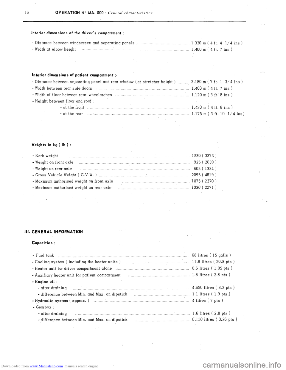
Interior dimensions of the driver’s compartment :
I Distance between windscreen and separatinq panels . . . . . .
1 330 m ( 4 ft. 4 l/4 ins )
Width at elbow heiqht . . . . . . . . . . . . . . . . . . . . . . . . . . . . . . . . .._........ ,.....,............., _._._....._..
1.400 m ( 4 ft. 7 ins )
Interior dimensions of patient comportment :.
- Distance between separatinq panel and rear window (at stretcher heiqht ) .._..._.. 2.180 m ( 7 ft. 1 3/4 ins )
_ Width between rear side doors
. . . . . . . . . . . . . . . . . . . . . . . . . . . . . . . . _._.. 1.400 m ( 4 ft. 7 ins )
_ Width of floor between rear wheelarches _.... 1.120 m ( 3 ft. 8 ins )
- Height between floor and roof
- at the front .._.._....,.......,..,,,,,,..,.,._..._.. _....................................... 1.420 m ( 4 ft. 8 ins )
- at the rear . . .._....._..__..._._._.......... .._.. .._._._.. 1.175 m ( 3 ft. 10 l/4 ins)
Weights in kg ( lb ) :
- Kerb weight ................................................................................................... 1530 ( 3373 )
- Weight on front axle
..................... ............................................... ...................... 925 ( 2039 )
- Weight on rear axle
.... 605 ( 1334 )
- Gross Vehicle Weight ( G.V.W. ) ........................................................................... 2095 ( 4619 )
- Maximum authorised weight on front axle ........................................................ 1075 ( 2370 )
- Maximum authorised weight on rear axle ‘1030 ( 2271 ) ...........................................................
111. GENERAL INFORMATION
Capacities :
- Fuel tank ............................................................................................................ 68 litres ( 15 galls )
- Cooling system ( including the heater units ) ....................................................... 11.8 litres ( 20.8 pts )
- Heater unit for driver compartment alone .............................................................. 0.6 litres ( 1.05 pts )
- Auxiliary heater unit for patient compartment ................................................... 1.6 litres ( 2.8 pts )
- Engine oil
- after draining ................................................................................................ 4.650 litres ( 8.2 pts )
- difference between Min. and Max. on dipstick ...................... . .......................
i.i litres ( 1.9 pts )
- tiydraulic system ( approx. )
.......... . ..................................................................... 4 litres ( 7 pts )
- Gearbox :
- after draining ............................................................................................... 1.6 litres ( 2.8 pts )
-difference between Min. and Max. on dipstick
.............................................. 0.150 litres ( 0.26 pts )
Page 55 of 394
Downloaded from www.Manualslib.com manuals search engine 4 OPERATION No MA. 100-00 : ChargctrJristics and special jeattlws of the engine. II. PARTICULAR FEATURES.
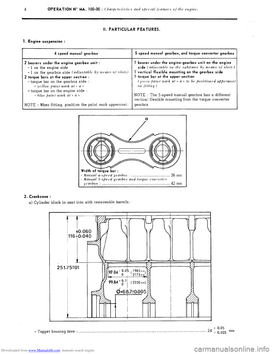
1. Engine sugpension :
4 speed manual gearbox
2 bearers under the engine gearbox unit :
- 1 on the engine side
- 1 on the gearbox side (adjustable by means o/ slots)
2 torque bars at the upper section :
- torque bar on the gearbox side :
- yellow paint mark at (( a ))
- torque bar on the engine side :
- blue paint mark at (( a ))
NOTE : When fitting, position the paint mark uppermost.
5 speed manual gearbox, and torque converter gearbox
bearer under the engine-gearbox unit on the engine
side
(adirrstable OH the subjranra by means oj slots)
vertical flexible mounting on the gearbox side
torque bar at the upper se‘ction
(green paint mark at CC a n to be positioned uppermost
072 jittiug )
NOTE : The 5-speed manual gearbox has a different
vertical flexible mounting from the torque converter
gearbox
a
- Mat7~ral gearbox : . . . . . . . . . . . . . . . . . . . . . . . . . . . . . . . . . . . . 36 mm - Manual S-speed gc,arbox and torque cowrvrtcr gearbox : . . . . . . . . . . . . . . . . . . . . . . . . . . . . . . . . . . . . . . . . . . . . . . . . . . . . . . . . . . . . . . . . 42 mm 2. Crankcase :
a) Cylinder block in oast iron with removeable barrels.
+ 0.05 - Tappet housing bore : . . . . . . . . . . . . . . . . . . . . . . . . . . . . . . . . . . . . . . . . . . . . . . . . . . . . . . . . . . . . . . . . . . . . ..~.................................................
24 + 0.025 mm
Page 58 of 394
Downloaded from www.Manualslib.com manuals search engine Op. MA. 100-00 7
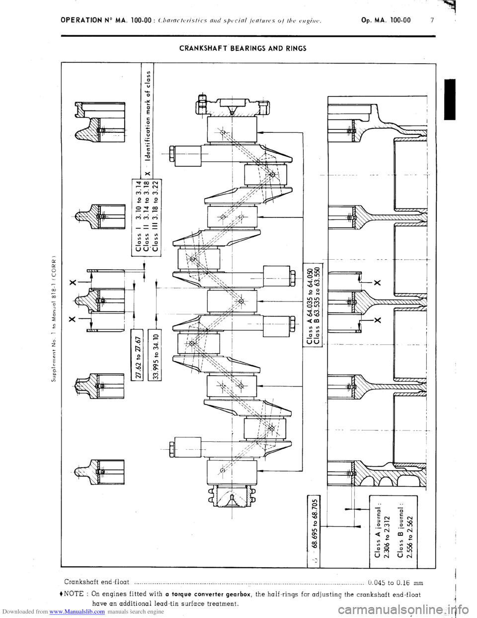
CRANKSHAFT BEARINGS AND RINGS
Crankshaft end-float . . . . . . . . . . . . . . . . . . . . . . . . . . . . . . . . . . . . . . . . . . . . . . . . . . . . . . . . . . . . . . . . . . . . . . . . . . . . . . . . . . . . . . . . . . . . . . . . . . . . . . . . . . . . . . . . . . . . . . . . .....
b.045 to 0.16 mm
+NOTE : On engines fitted with a torque converter gearbox,
the half-rings for adjusting the crankshaft end-float
have an additional lead-tin surface treatment.
Page 68 of 394
Downloaded from www.Manualslib.com manuals search engine OPERATION No MA. 100-00 : Characteristics and special jeafruvs oj the cvlghv.
Op. MA. 100-00 17
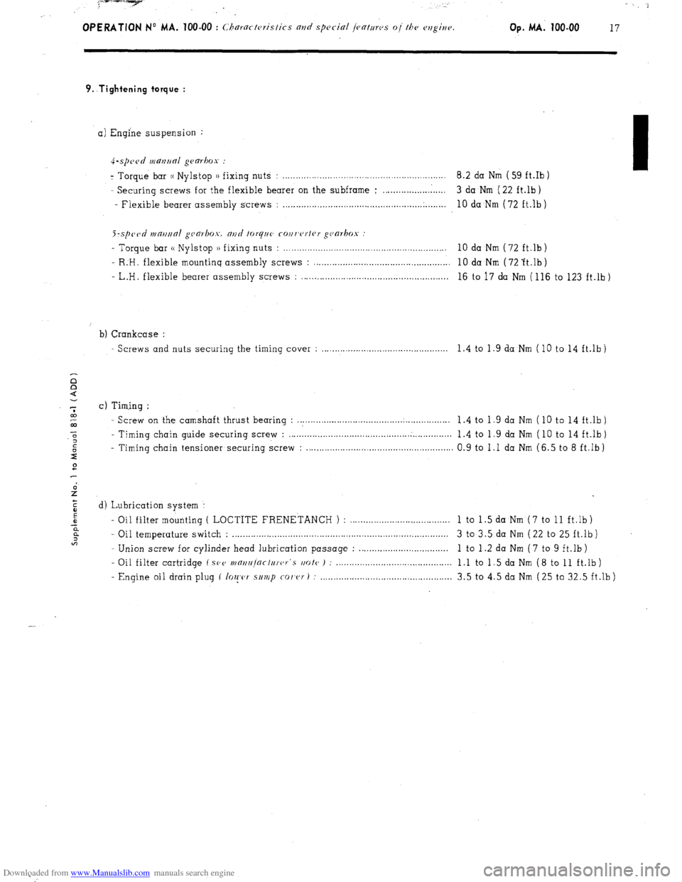
9..Tightening torque :
a) Engine suspension :
4-.spc~~d manrlal gearbox :
7 Torque bar (( Nylstop )) fixing nuts : .............................................................. 8.2 da Nm ( 59 ft.Ib )
- Securing screws for the flexible bearer on the subframe ; ........................ 3 da Nm ( 22 ft.lb)
- Flexible bearer assembly screws :
..................................................... .
........ 10 da Nm (72 ft.lb)
S-sp~~tl n1m11ra1 gca~box. and forq~~c cour,c~rtrr gc~arkos
- Torque bar (( Nylstop )) fixing nuts : . . . . . . . . . . . . . . . . . . . . . . . . . . . . . . . . . . . . . . . . . . . . . . . . . . . . . . . . . . . . . . 10 da Nm (72 ft.lb)
- R:H. flexible mountinq assembly screws : . . . . . . . . . . . . . . . . . . . . . . . . . . . . . . . . . . . . . . . . . . . . . . . . . . . . 10 da Nm ( 72 ‘ft.lb )
- L.H. flexible bearer assembly screws : . . . . . . . . . . . . . . . . . . . . . . . . . . . . . . . . . . . . . . . . . . . . . . . . . . . . . . . . 16 to 17 da Nm ( 116 to 123 ft.lb )
b) Crankcase :
Screws and nuts securing the timing cover : . . . . . . . . . . . . . . . . . . . . . . . . . . . . . . . . . . . . . . . . . . . . . . 1.4 to 1.9 da Nm (10 to 14 ft.lb)
c) Timing :
- Screw on the camshaft thrust bearing : . . . . . . . . . . . .._............................................ 1 .4 to 1 .9 da Nm ( 10 to 14 ft.lb )
- Timing chain guide securing screw : . . . . . . . . . . . ..__................................ . . . . . . . . . . . . . . .
1.4 to 1.9 da Nm ( 10 to 14 ft.lb)
- Timing chain tensioner securing screw : . . . . . . . . . . . . . . . . . . . . . . . . . . . . . . . . . . . . . . . . . . . . . . . . . . . . . . . 0.9 to 1 .I da Nm (6.5 to 8 ft.lb )
d) Lubrication system :
- Oil filter mounting ( LOCTITE FRENETANCH ) : ......................................
1 to 1 .5 da Nm ( 7 to 11 ft.lb )
- Oil temperature switch : .................................................................................. 3 to 3.5 da Nm ( 22 to 25 ft.lb )
- Union screw for cylinder head lubrication passage : ..................................
1 to 1 .2 da Nm ( 7 to 9 ft.lb )
- Oil filter cartridge ( SPV
wnrt/r]nctc/rer‘s rmte ) : ............................................ 1 .l to 1 .5 da Nm ( 8 to 11 ft.lb )
- Engine oil drain plug ( lo~!,c,r s/t~/p
co/‘cr) : .................................................. 3.5 to 4.5 da Nm (25 to 32.5 ft.lb)
Page 71 of 394
Downloaded from www.Manualslib.com manuals search engine OPERATION No MA. 120.0 : Chrrki,,~ the /iminp. Op. MA. 120-O 1
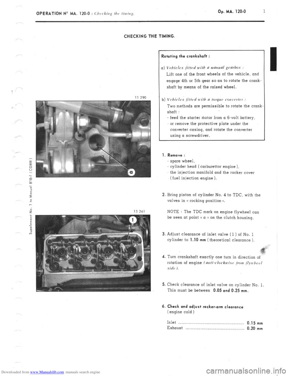
CHECKING THE TIMING.
lototing the crankshah :
) Vebirl~s /i/fed with a mantra~ gearbox :
Lift one of the front wheels of the vehicle, and
engage’ 4th or 5th gear so as to rotate the crank-
shaft,
by means of the raised wheel.
1) Vehicles /itted with n torqee ronrwrter :
Two methods are permissible to rotate the crank
shaft :
- feed the starter “iota from (I &volt battery,
or remove the protective plate under the
converter casing, and rotate the converter
using a screwdriver.
1. Remove :
spore wheel,
cylinder head (carburettor engine 1,
the injection manifold and the rocker cover
(fuel injection engine 1.
2. Bring piston of cylinder No. 4 to TDC. with the
valves in (( rocking position x
NOTE : The TDC mark on engine flywheel co”
be see” at point (( a )) on the clutch housing.
3. Adjust clearance of inlet valve ( 1 ) of No. 1
cylinder to
1.10 mm (theoretical clearance 1.
4. Turn crankshaft exactly one turn in direction of
rotation of engine f m/i-clockwise iro>t! /lyre hpel
side I.
5. Check clearance of inlet valve on cylinder No. 1.
This must be between 0.05
and 0.25 mm.
6. Check and adiust rocker-arm clearance
(engine cold )
Inlet .__....__.............................................,.,, 0.1 5 mm
Exhaust . . . . . . . . . . . . . . . . . . . . . . . . . . . . . . . . . . . . . . . . . . . . . . . . . . . . 0.20 mm
Page 152 of 394
Downloaded from www.Manualslib.com manuals search engine IGNITION
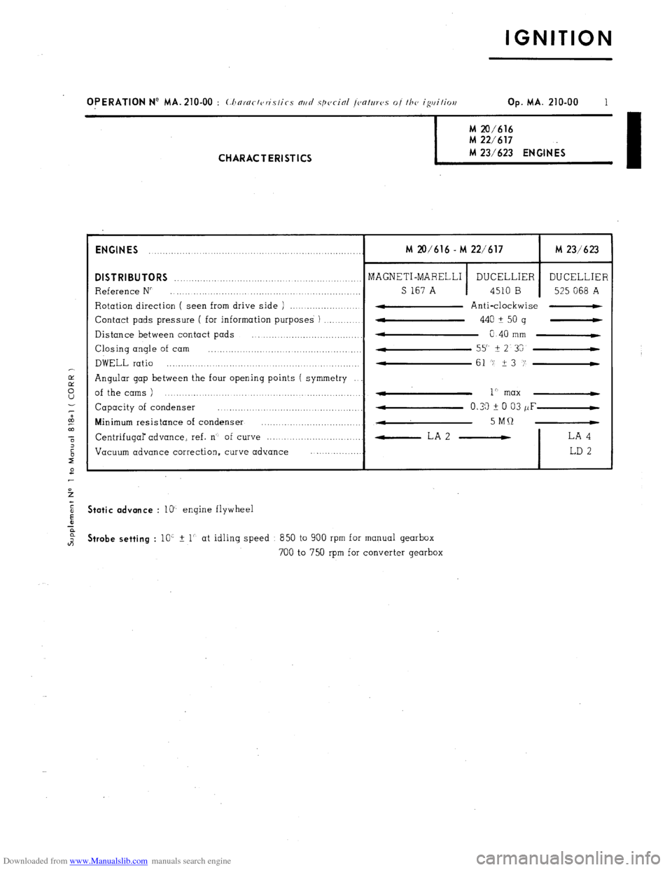
OPERATION N’ MA. 210-00 : (:horr/r/c,ri.s/ics nrtrl spccinl /C,O/UTCJS of /he igtti/ioe Op. MA. 210-00 1 M 20/616
M 22/617 M 23/623 ENGINES
I CHARACTERISTICS
ENGINES
........ ........... ................................................. M 20/616 - M 22/617 M 23/623
DISTRIBUTORS ........................................... MAGNETI-MARELLI _._ ..............
DUCELLIER DUCELLIER
Reference N” ........................... .., ............................. _._ S 167 A 4510 B 525 068 A
Rotation direction ( seen from drive side ) ....................... 4 Anti-clockwise -
Contact pads pressure ( for information purposes ) ..............
w 440 A
50 g -
Distance between contact pads
* ................................... 0 40 mm C
Closing angle of cam ................... .................................. 55" It
2 3G
DWELL ratio ............................................... 4
....... .......... 61 -7 23 i’-
Angular gap between the four opening points ( symmetry
of the cams ) ....................................................... - 1” max 4
Capacity of condenser ......... ... ............... ...... ........ 4 0.33 i 0 03 /IF-
Minimum resistance of condenser ...............................
., ...
4 5MQ -
Centrifugal advance, ref. n’- of curve ................................. -LA2 - LA 4
Vacuum advance correction, curve advance ..................
LD 2 Static advance
: lo’- engine flywheel Strobe setting
: 10’ % 1’. at idling speed 850 to 900 rpm for manual gearbox
700 to 750 rpm for converter gearbox
Page 185 of 394
Downloaded from www.Manualslib.com manuals search engine TORQUE CONVERTER
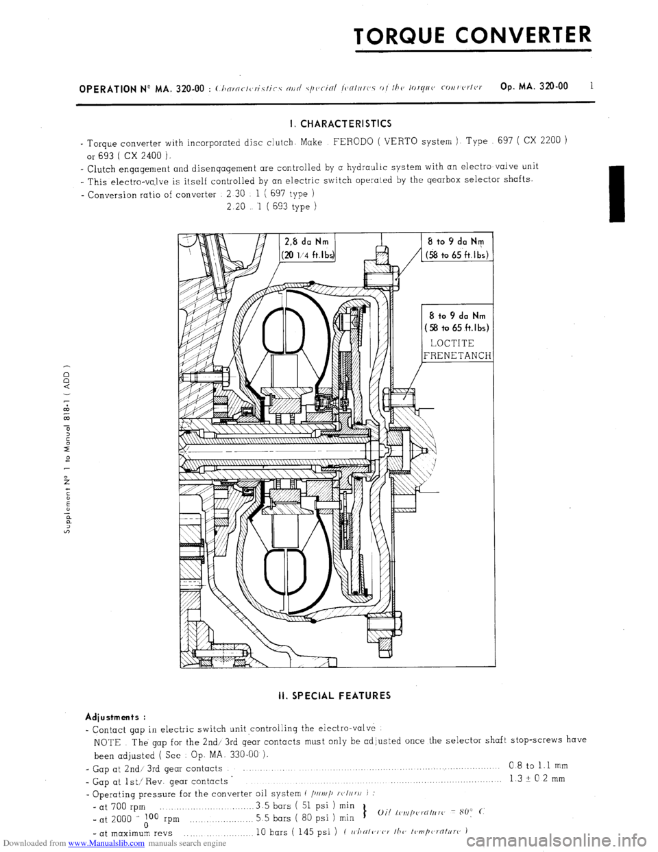
I. CHARACTERISTICS
- Torque converter with incorporated disc clutch. Make FERODO ( VERTO system ). Type 697 ( CX 2200 )
or 693 ( CX 2400 ).
_ Clutch engagement and disengagement are controlled by a hydraulic system with an electro valve unit
I This electro-va,lve is itself controlled by an electric switch operated by the gearbox selector shafts.
- Conversion ratio of converter 2 30 1 ( 697 type )
2.20 1 ( 693 type ) II. SPECIAL FEATURES
Adiustments :
- Contact gap in electric switch unit ,controlling the electro-valve
NOTE The gap for the 2nd/ 3rd gear contacts must only be adjusted once the selector shaft stop-screws have
been adjusted ( See Op. MA. 330-00 ),
- Gap at 2nd/ 3rd gear contacts 0 8 to 1.1 mm
- Gap at lst/ Rev. gear contacts ’ 13+02mm
. . . . . . . . . . . . .._.......
- Operating pressure for the converter oil system c /)IIv//~ ~c,I//v/I J :
- at 700 rpm 3.5 bars ( 51 psi ) min
_ at 2000 i A00 rpm 5.5 bars ( 80 psi 1 min 1
Oil l,c~~~i/~~~i’NItrrc~ 80: (.
- at maximum revs .,......... 10 bars ( 145 psi ) ( II./IN/<‘I (‘7 /h(, I<,ml,(a,‘flt~ro )
Page 189 of 394
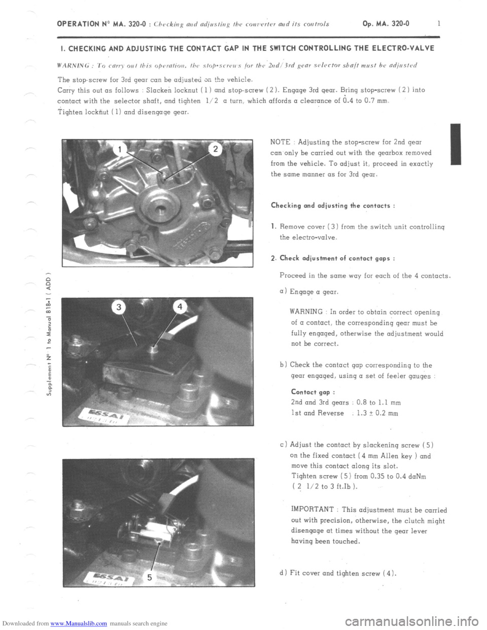
Downloaded from www.Manualslib.com manuals search engine OPERATION No MA. 320-O : Checking md czdjssting fhe ronw’rtcv artd its corrtrols Op. MA. 320.0 1 I. CHECKING AND ADJUSTING THE CONTACT GAP IN THE SWITCH CONTROLLING THE ELECTRO-VALVE
The stopscrew for 3rd gear can be adjusted SK the vehicle.
Carry this out as follows : Slacken locknut ( 1 ) and stopscrew (2 ). Engage 3rd gear. Bring stop-screw i 2 1 into
contact with the selector shaft. and tighten l/2 a turn, which affords a clearance of a.4 to Cl.7 mm.
Tighten lockfiut ( 1) and disengage gear.
NOTE : Adjusting the stop-screw for 2nd gear
con only be carried out with the gearbox removed
from the vehicle. To adjust it, proceed in exactly I
the same manner as for 3rd gear. Checking and adjusting the contacts :
1.
Remove cover ( 3) from the switch unit controliinq
the electro-valve. 2. Check adjustment of contact gaps :
Proceed in the same way far each of the 4 contacts.
a) Engage a gear.
WARNING In order to obtain correct opening
of a contact, the corresponding gear must be
fully engaged. otherwise the adjustment would
not be correct.
b) Check the contact gap corresponding to the
gear engaged, using a set of feeler gauges : Contact gap :
2nd
and 3rd gears 0.8 to 1.1 mm
1st and Reverse 1.3 ? 0.2 mm
c 1 Adjust the contact by slackening screw ( 5)
on the fixed contact (4 mm Allen key ) and
move this contact along its slot.
Tighten screw ( 5) from 0.35 to 0.4 doNm
( 2 l/2 to 3 ft.Ib ).
IMPORTANT : This adjustment must be carried
out with precision, otherwise, the clutch might
disengage at times without the gear lever
having been touched.
d 1 Fit cover and tighten screw ( 4 1.
Page 190 of 394

Downloaded from www.Manualslib.com manuals search engine GEARBOX
4-SPEED MANUAL GEARBOX
I. CHARACTERISTICS
1. Gear ratios :
NOTE
Speeds are given for vehicles equipped with 185 SR 14 ZX, 185 SR 14 XZX or 185 HR XVS tyres. the
rolling circumference of which is 1 970 m under load.
a) cc All CX Vehicles u gearbox :
I
Gears
I Gearbox ratios
I 1st
I ( 12138 ) 3 1666 1
I 2nd
I ( 18133) 1.8333 1
I 3rd
I ( 30/34) 1 1333 1 Final
drive ratio Overall ratios
I 8 7434 1
13/ 62
4 769 1
I 15.3411 1 Speed at IOO? rpm
in km/h (mph)
7 82 ( 4.89 )
13 51 (8 44 1
21 86 ( 13 66 !
Speedometer drive ratio 5 12 7 85 ( 4.95 1
b) ss Economy option D gearbox on CX 2000 -1 107j
Gears
1st
2nd
3rd
4th
Reverse Gearbox ratios
( 12/38
) 3 1666 1
( 18/33 ) 1.8333 1
( 3W34 1 1.1333
1
( 36/27 ) c,75 1
( 13/ 41) 3 1538 1 Final
drive ratio Overall ratios Speed at 1002 rpm
in km/ h ( mph 1
13 7973 1 8.56 ( 5 35 1
7 9879 1 14.79
( 9.24 ! I
I
14161
4357 1
4 9379 1 23.93
i 14.96 )
3 2678 1
13.7415 1 ( 5.38
Speedometer drive ratio 5 x 11