relay Citroen CX 1981 1.G Owner's Manual
[x] Cancel search | Manufacturer: CITROEN, Model Year: 1981, Model line: CX, Model: Citroen CX 1981 1.GPages: 394
Page 329 of 394
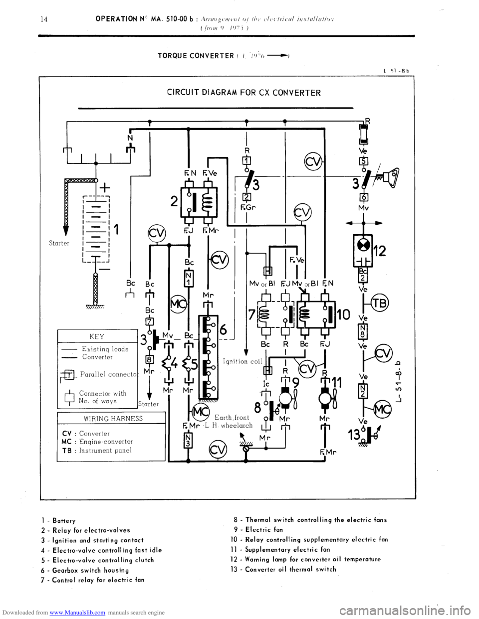
Downloaded from www.Manualslib.com manuals search engine TORQUE CONVERTER ( I ‘/+(I -I
1 51-Rh
CIRCUIT DIAGRAM FOR CX CONVERTER
kd i- I I I c
I I Bc Bc
*
KEY
- Existinq leads G
- Converter
6
8
;a
Parallel connecto- Mr
0 Connector with
No. of ways i
Starter
01 ---
I Bc k l3i F;J
E Mr ,L H wheelarch
A m
I 1
EMr
to TB
Ve
P n
Ve +
1 - Battery
2 - Relay for electro-valves
3 - Ignition and starting contact
4 - Electra-valve controlling fast idle
5 - Electra-valve controlling clutch
6 - Gearbox switch housing
7 - Control relay for electric fan 8 - Thermal switch corrtrolling the electric fans
9 - Electric fan
10 - Relay controlling supplementary electric fan
11 - Supplementary electric fan
12 - Warning lamp for converter oil temperature
13 - Converter oil thermal switch
Page 332 of 394
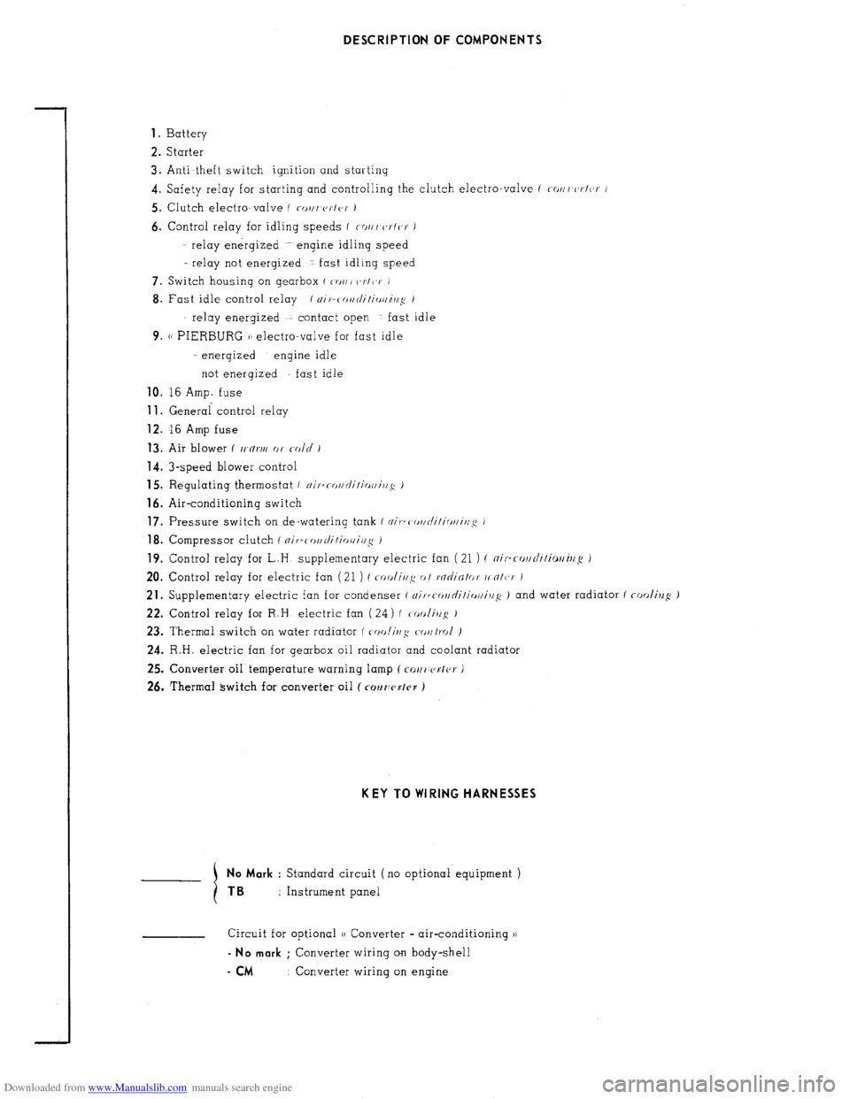
Downloaded from www.Manualslib.com manuals search engine DESCRIPTION OF COMPONENTS
1.
Battery
2. Starter
3. Anti-theft switch ignition and starting
4. Safety relay for starting and controlling the clutch electro-valve f ~/lr,c,r/(,r J
5. Clutch electro-valve ( co,/, V~IO~ J
6. Control relay for idling speeds f W//I r,~/or J
relay energized engine idling speed
- relay not energized 1 fast idling speed
7. Switch housing on gearbox ( WJ,, c,~/(,v J
8. Fast idle control relay / ~i)-c o~r/i/ir~//i,l~ 1
relay energized contact open fast idle
9. (( PIERBURG )) electro-valve for fast idle
- energized engine idle
not energized fast idle
10. I6 Amp. fuse 11.
General control relay 12.
16 Amp fuse 13.
Air blower ( tr’n~r// or c-old ) 14.
3-speed blower control
15. Regulating thermostat ( ~i,.=ror,c/i/irrr,i,l~: i
16. Air-conditioning switch 17.
Pressure switch on de-watering tank f ni,-=( or~rli/irrr/i~~~c ) 18.
Compressor clutch f nifsc o//di/io~i/l~ i 19.
Control relay for L.H supplementary electric fan (21 ) ( ~il..r~l/di/io//il/~ )
20. Control relay for electric fan (21 ) (
coolir~g o/ rficJiNlor (I nlc,r )
21. Supplementary electric fan for condenser ( ~il.~rol/ni/i~~ll/i//~ ) and water radiator ( cooling: J
22. Control relay for R.H electric fan ( 24) ( tooli~!: J
23. Thermal switch on water radiator ( (r)olir~,r~ to~trol )
24. R.H. electric fan for gearbox oil radiator and coolant radiator
25. Converter oil temperature warning lamp ( CM, c~sl~r J
26. Thermal switch for converter oil ( COMWKI~B ) KEY TO WI RING HARNESSES
No Mark
: Standard circuit (no optional equipment ) TB :
Instrument panel
Circuit for optional (( Converter - air-conditioning )) - No mark
; Converter wiring on body-shell
- CM : Converter wiring on engine
Page 333 of 394
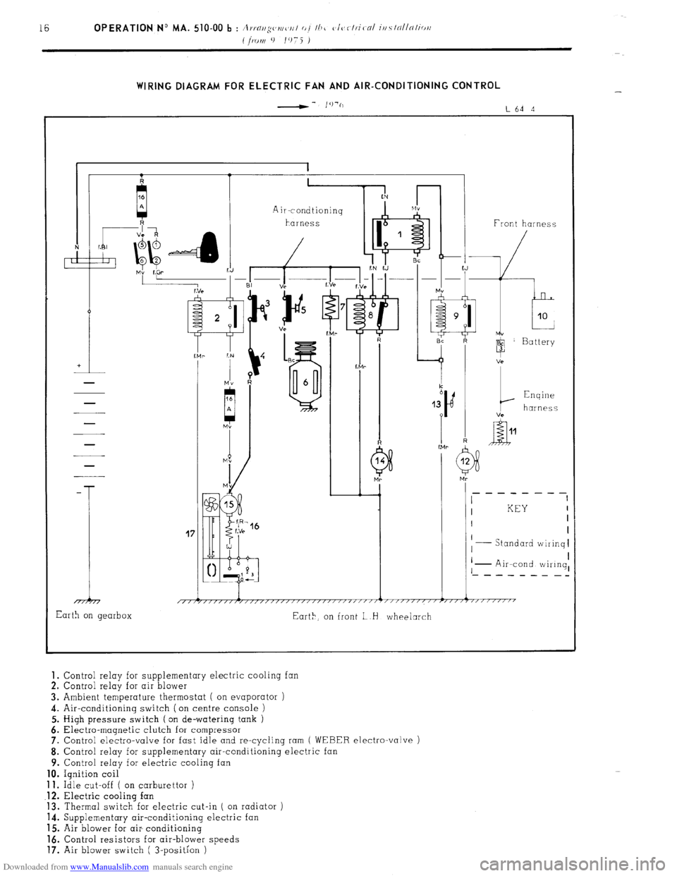
Downloaded from www.Manualslib.com manuals search engine WIRING DIAGRAM FOR ELECTRIC FAN AND AIR-CONDITIONING CONTROL
-- I’)‘(,
L64 4
41 1 1 Front harness
-
T
17
I KEY I
I I
I
Standard wiiinq I
I I
I I
I - Air-cond wiIinq, ‘- - - - - - - _-
1 i 1 1 1
/,/r/////,/,,,,/,//////~////~‘/‘~””’~”””””~””7”“““’
Earth on gearbox
Eart>, on front L H wheelarch 1.
Control relay for supplementary electric cooling fan
2. Control relay for air blower
3. Ambient temperature thermostat ( on evaporator )
4. Air-conditioning switch (on centre console )
5. High pressure switch ( on de-watering tank )
6. Electra-magnetic clutch for compressor
7. Control electro-valve for fast idle and re-cycling ram
( WEBER electro-valve )
8. Control relay for supplementary air-conditioning electric
9. Control relay for electric cooling fan 10.
Ignition coil 11.
Idle cut-off ( on carburettor ) .12.
Electric cooling fan
13. Thermal switch for electric cut-in ( on radiator )
14. Supplementary air-conditioning electric fan
15. Air blower for air- conditioning 16.
Control resistors for air-blower speeds 17.
Air blower switch ( 3-position )
Page 334 of 394
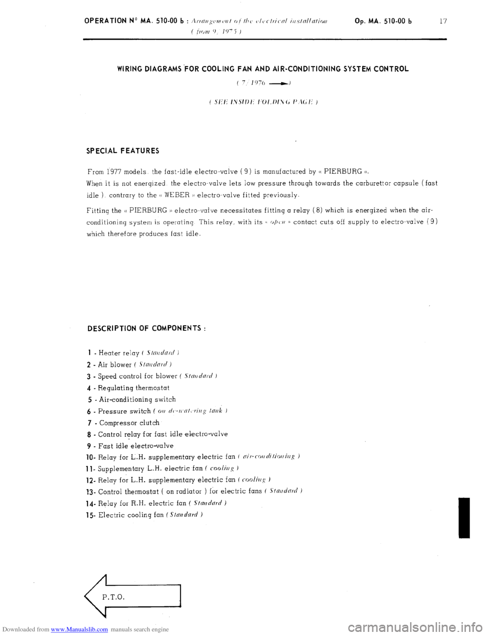
Downloaded from www.Manualslib.com manuals search engine Op. MA. 510-00 b 17 WIRING DIAGRAMS’FOR COOLING FAN AND AIR-CONDITIONING SYSTEM CONTROL
SPECIAL FEATURES
From 1977 models the fast-idle electro-valve ( 9) is manufactured by 1, PIERBURG 1).
When it is not enerqized the electro-valve lets low pressure through towards the carburettor capsule (fast
idle ) contrary to the (1 WEBER )) electromvalve fitted previously.
Fitting the N PIERBURG )) electro-valve necessitates fitting a relay (8) which is enerqized when the air-
conditioning system is operating This relay, with its c( o/)t/i 1) contact cuts off supply to electro-valve (9)
which therefore produces fast idle. DESCRIPTION OF COMPONENTS :
1
- Heater relay ( .s/o~/~/Q~c/ )
2 - Air blower ( .S~n~~dnr(i i
3 - Speed control for blower ( S/nr/clnrt/ J
4 - Regulating thermostat
5 - Air-conditioning switch 6
- Pressure switch ( 01, dc,-rt,cr/t,rit,,q lnr~k ) 7
- Compressor clutch
8 - Control relay for fast idle melectro-valve
9 - Fast idle electro-valve lo-
Relay for L.H. supplementary electric fan f nip-cor/rli/ior/illS ) 1
I- Supplementary L.H. electric fan ( foolir2~~ ) 12-
Relay for L.H. supplementary electric fan ( cooli~/g ) ?3-
Control thermostat ( on radiator ) for electric fans ( Stnr~d& )
14- Relay for R.H. electric fan ( Stmzdnrrl )
15 Electric cooling fan ( Stal?dn~/ )
Page 338 of 394
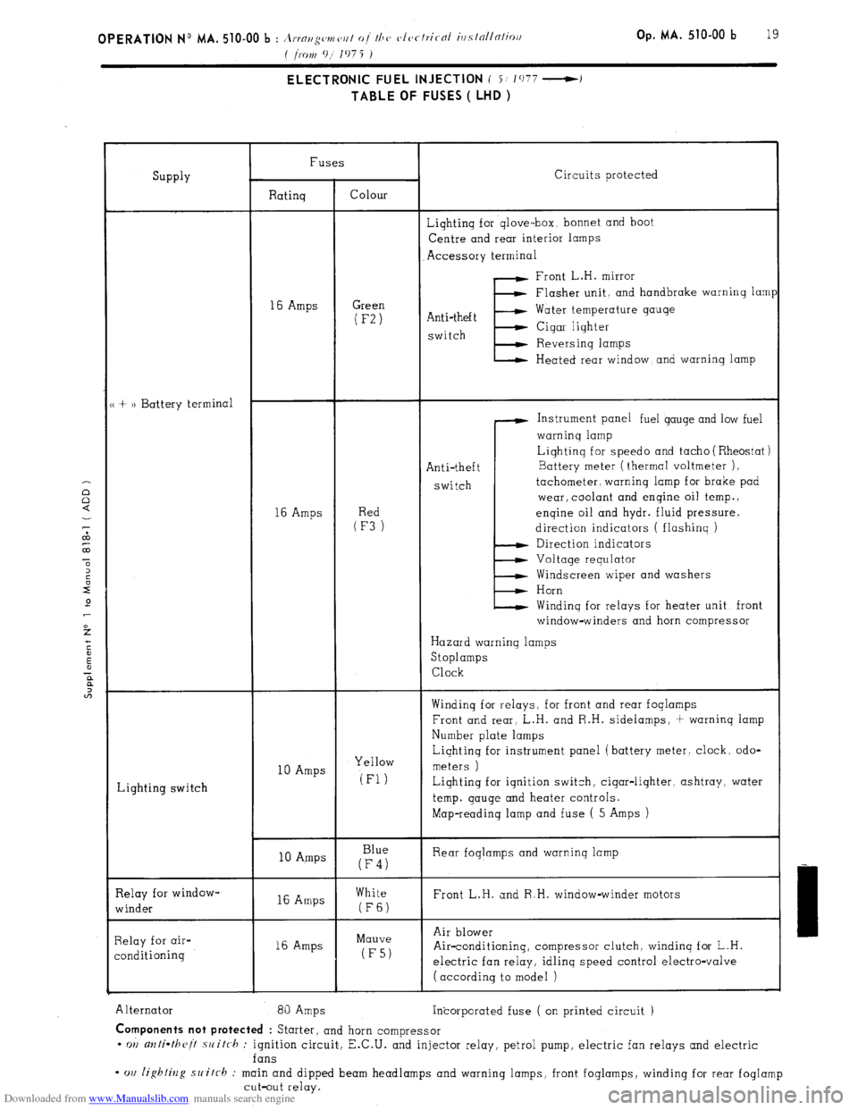
Downloaded from www.Manualslib.com manuals search engine Op. MA. 510-00 b 19 ELECTRONIC FUEL INJECTION ( i/ 1077 -)
TABLE OF FUSES ( LHD )
SUPPlY Fuses
Circuits protected
Ratinq Colour
Lightinq for qlove-box, bonnet and boot
Centre and rear interior lamps
Accessory terminal
Front L.H. mirror
16 Amps Green (F-2)
Flasher unit. and handbrake warninq lam1
Anti-theft
E Water temperature gauge
switch Cigar lighter
Reversinq lamps
Heated rear window, and warning lamp
+ )) Battery terminal
Instrument panel fuel gauge and low fuel
warninq lamp
Anti-theft
switch Liqhtinq for speed0 and tacho ( Rheostat )
16 Amps
(RFe3d)
_ Battery meter (thermal voltmeter ).
tachometer, warning lamp for brake pad
wear, coolant and engine oil temp. 1
enqine oil and hydr. fluid pressure.
direction indicators ( flashing )
Direction indicators
Voltage requlator
Windscreen wiper and washers
Horn
Windinq for relays for heater unit front
window-winders and horn compressor
Hazard warning lamps
Stoplamps
Clock
Winding for r-elays, for front and rear foglamps
Front and rear, L.H. and R.H. sidelamps, + warninq lamp
Number plate lamps
Lighting switch 10 Amps Yellow Liqhtinq for instrument panel (battery meter. clock. odo-
meters )
(Fl) Lighting for iqnition switch, cigar-lighter, ashtray, water
temp. gauge and heater controls.
Map-reading lamp and fuse ( 5 Amps )
10 A.mps Blue
(F4) Rear foglamps and warninq lamp
Relay for window-
winder 16 Amps White
Front L.H. and R.H. window-winder motors (FE)
Relay for air-
conditioning 16 Amps Mauve
(F5) Air blower
Air-conditioning, compressor clutch, windinq for L.H.
electric fan relay, idlinq speed control electro-valve
( according to model )
Alternator 81) Amps
Incorporated fuse ( on printed circuit ) Components not protected
: Starter, and horn compressor
- OII anti-theit .switrh : ignition circuit, E.C.U. and injector relay, petrol pump, electric fan relays and electric
fans
- cm lighting switch : main and dipped beam headlamps and warning lamps, front foglamps, winding for rear foglamp
cut-out relay.
Page 340 of 394
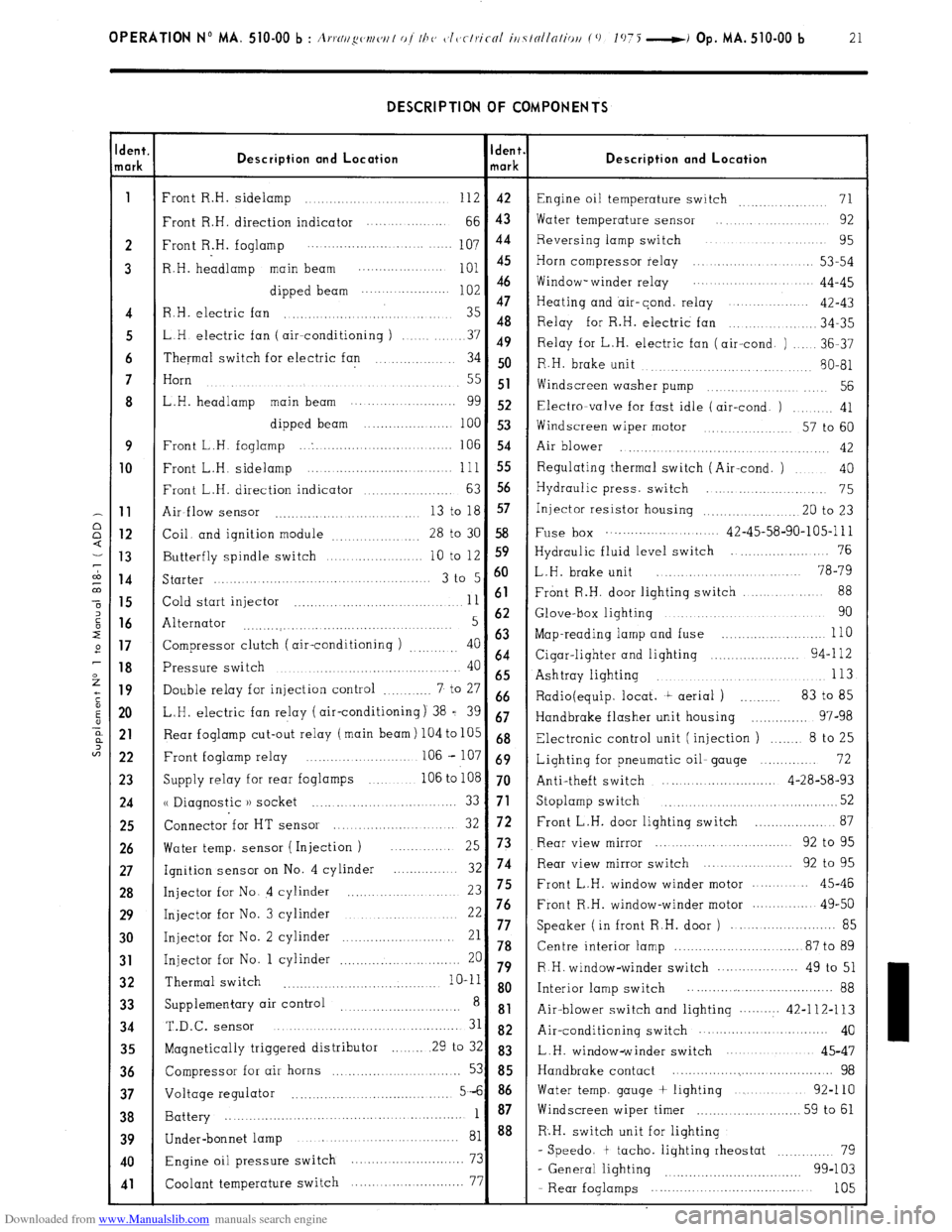
Downloaded from www.Manualslib.com manuals search engine OPERATION No MA. 510-00 b : A,.,.N//~w~/w/ of I/J<, c~l~~clriccrl iti7tollnliou (0 1075 -i Op. MA. 510-00 b 21 DESCRIPTION OF COMPONENTS
dent.
lark Description and Location Ident.
mark Description and Location
1
Front R.H. sidelamp ............................ 112 42
Engine oil temperature switch 71 ...............
Front R.H. direction indicator .... ... .........
66 43 Water temperature sensor .... .............. 92
2 Front R.H. foglamp 107 44 Reversing lamp switch ................... 95
..................... ....... ....
3 R.H. headlamp main beam
;:: :: Horn compressor relay ..................... 53-54
............... ....
dipped beam Window- winder relay .................. 44-45
......................
47
Heating and air-cond. relay ...............
4 R.H. electric fan ............................... 35 42-43
48
.............. 34-35
5 LH electric fan ( air--conditioning ) Relay for R.H. electric fan
........ 37 49
Relay for L.H. electric fan (air-cond. ) ..... 36-37
6 Thermal switch for electric fan .............. 34 50
R.H. brake unit
........... 80-81
......... ............
7 Horn
....................................
.......... ..... 55 51
Widscreen washer pump .............. .... 56
8 L.H. headlamp main beam ........... ..........
gg 52 Electra-valve for fast idle (air-cond. ) ......... 41
dipped beam ......................
100 53
Windscreen wiper motor ............. 57 to 60
9 Front L.H. foglamp ... . ...............................
106 54
Air blower ..............
........... ..... ........... 42 10
Front L.H. sidelamp ......................... ... ... .. 111 55 Regulating thermal switch (Air-cond. ) .... 40
Front L.H. direction indicator
63 56 ................... Hydraulic press. switch .......................
75 11
Air-flow sensor 13 to 18 57
........................... ... Injector resistor housing .................... .20 to 23 12
Coil. and ignition module
28 to 30 58 Fuse box ............................ 42-45-58-90-105-l 11
................. 13
Butterfly spindle switch 10 to 12 S9 Hydraulic fluid level switch ...................... 76
.................... 14
Starter 3 t0 5 6o L.H. brake unit ........................ 78-79
..........................................
88 15
Cold start injector 11 61 Front R.H. door lighting switch ....... ....
.................................. 16
Alternator 5 62 Glove-box lighting ................................ 90
...........
....... ..................... ....... 17
Compressor clutch ( air-conditioning ) 40 63 Map-reading lamp and fuse ............... ..... ... 110
.........
64 18
Pressure switch 40 Cigar-lighter and lighting ...................... 94-l 12
........................................
65 Ashtray lighting 113 ..................................... 19
Double relay for injection control 7 to 27 ............ 66
Radio(equip. locat. t aerial ) .......... 83 to 85
20 L.H. electric fan relay (air-conditioning) 38 = 39 67
Handbrake flasher unit housing .............. 97-98 21
Rear foglamp cut-out relay (main beam) 104 to 105 68
Electronic control unit (injection ) ....... 8 to 25
22 Front foglamp relay ....................... .. 106 - 107 69
Lighting for pneumatic oil- gauge .............. 72
23
Supply relay for rear foglamps ............ 106 to 108 70
Anti-theft switch ............................ 4-28-58-93 24
u Diagnostic )) socket 52 ......... ....... ... ..... ........ 33 71 Stoplamp switch ...................................... 25
Connector for HT sensor 72 ................... 87
....................... 32 Front L.H. door lighting switch 26
Water temp. sensor ( Injection ) Rear view mirror ............................ 92 to 95
... 25 73
27
Ignition sensor on No. 4 cylinder 32 74 Rear view mirror switch ................... 92 to 95
............. 28
Injector for No. 4 cylinder ...................... 23 75 Front L.H. window winder motor .......... 45-46 29
Injector for No. 3 cylinder 22 76 Front R.H. window-winder motor .............. 49-50
...........................
......................... 85 30
Injector for No. 2 cylinder 21 77 Speaker ( in front R.H. door )
......................... 78 Centre interior lamp ............................... 87 to 89 31 Injector for No. 1 cylinder 20 ............................. 79 R H. window-winder switch .................... 49 to 51 32 Thermal switch
........... .......................... 10-11 8 o
Interior lamp switch .................... ................ 88
33 Supplementary air control ............................
8 81
Air-blower switch and lighting .......... 42-112-113 34 T.&c.
SenSOr ........................................... 31 82 Air-conditioning switch ............... ............ 40
35
Magnetically triggered distributor ........ 29 to 32 83
L.H. window-winder switch .....................
45-47 36
Compressor for air horns ............. ..... ......... 53 85 Handbrake contact ......................................... 98 37
Voltage regulator 5-6 86 Water temp. gauge + lighting ..................
92-110
....................................... 38
Battery 1 87 Windscreen wiper timer
.......................... 59 to 61
....................................................... 39
40
41
Under-bonnet lamp ........................................ 81 88 R.H. switch unit for lighting
Engine oil pressure switch 73 - Speedo. t tacho. lighting rheostat ............ 79
............................
99-103
Coolant temperature switch 77
- General lighting ................................
....... ....................
- Rear foglamps ..................................... 105
Page 365 of 394
Downloaded from www.Manualslib.com manuals search engine OPERATION No MA. 640-00 : (:hnrnc-/eris/ics nrtd s.pcc-in/ ~bntttrcs of I/T<< nir- Op. ihA. 640-00 5
c-ottdiliottittg systc~ttt
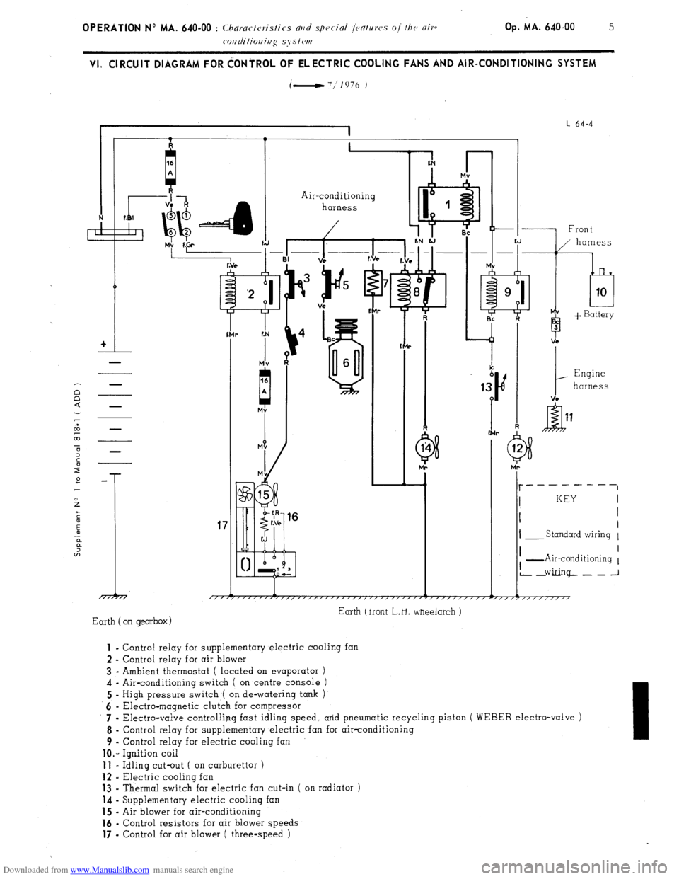
VI. ClRdUlT DIAGRAM FOR dONiROL OF ELECTRIC COOLING FANS AND AIR-CONDITIONING SYSTEM
(-'/lo76 )
I
I L 64-4
I 1. I
+I
-
Air-conditioning
harness
r
-I% ii.+
f:N
r
Mv
A
-1 Front
b 3
1
Engine
harness
VC -
I- __------
I KEY
I I
I
I- Standard wiring 1
17
/TTj I I
I -Air-conditioning 1
L2Ginq--~_J
Earth (front L.H. wheeiarch )
Earth on gearbox) 1
- Control relay for supplementary electric cooling fan
2 - Control relay for air blower
3 - Ambient thermostat ( located on evaporator )
4 - Air-conditioning switch ( on centre console )
5 - High pressure switch ( on de-watering tank )
6 - Electra-magnetic clutch for compressor
7 .
Electra-valve controlling fast idling speed, arid pneumatic recycling piston ( WEBER electro-valve )
8 - Control relay for supplementary electric fan for air-conditioning
9 - Control relay for electric cooling fan
lo.- Ignition coil 11
- Idling cut-out ( on carburettor ) 12
- Electric cooling fan 13
- Thermal switch for electric fan cut-in ( on radiator ) 14
- Supplementary electric cooling fan 15
- Air blower for air-conditioning 16
- Control resistors for air blower speeds 17
- Control for air blower ( three-speed )
Page 366 of 394
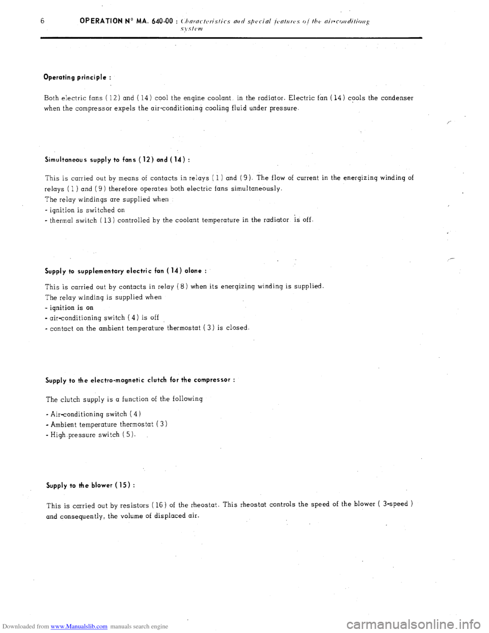
Downloaded from www.Manualslib.com manuals search engine Operating principle :
Both electric fans ( 12) and ( 14) cool the engine coolant in the radiator. Electric fan ( 14) cools the condenser
when the compressor expels the air-conditioning cooling fluid under pressure.
Simultaneous supply to fans (12) and (14) :
This is carried out by means of contacts in relays ( 1 ) and ( 9). The fl ow of current in the energizinq winding of
relays ( 1 ) and ( 9) therefore operates both electric fans simultaneously.
The relay windings are supplied when
- ignition is switched on
*
thermal switch ( 13) controlled by the coolant temperature in the radiator is off. _-
Supply to supplementary electric fan ( 14) alone :
This is carried out by contacts in relay ( 8) when its energizing winding is supplied
The relay winding is supplied when
- ignition is on
- air-conditioning switch ( 4) is off
a
contact on the ambient temperature thermostat ( 3) is closed.
Supply to the electro-magnetic clutch for the compressor :
The clutch supply is a function of the following
- Air-conditioning switch (4)
- Ambient temperature thermostat ( 3 )
-
High pressure switch ( 5).
Supply to the blower ( 15) :
This is carried out by resistors ( 16) of the rheostat. This rheostat controls the speed of the blower ( 3-speed )
and consequently, the volume of displaced air.
Page 367 of 394
Downloaded from www.Manualslib.com manuals search engine OPERATION No MA. 640-00 : (hnrnct~~tis~ics md special jenttrrvs of the nir-
coi~ditiouing systcw. 1 Op. MA. 640-00
7
VII. WIRING DIAGRAMS FOR COOLING FAN AND AIR-CONDITIONING SYSTEM CONTROLS
7.; 1976 - Special features :
From 1977 models, the fast-idle electro-valve ( 9) is manufactured by (( PIERBLJRG )).
When it is not energized. the electro-valve lets low pressure through to.wards the carburettor capsule (fast-
idle ) I contrary to the (( WEBER )) electro-valve fitted previously.
Fitting the (( PIERBURG )) electro-valve necessitates fitting a relay (8) which is energized when the air-
conditioning system is operating. This relay with its N open )) contact cuts off supply to electro-valve ( 9)
which therefore produces fast-idle.
The rest of the operation is identical to the preceding diagram. DESCRIPTION OF COMPONENTS :
1
- Heater relay ( standard )
2 - Air blower ( Stmdnrd )
3 - Speed control for blower f Stnudnrd )
4 - Regulating thermostat
5 - Air-conditioning switch
6 - Pressure switch ( on dc-wnkrivg t~rrk ,)
7 - Compressor cl.utch
8 - Control relay for fast-idle electro-valve
9 - Fast-idle electro-valve
10 - Relay f0r’L.H. supplementary electric fan ( air-rorzditio)litlg J 11
i Supplementary L.H. electric fan ( cooliug )
12 - Relay for L.H. supplementary electric fan ( cooling ) 13
- Control thermostat ( on radiator ) for electric fans ( Standard ) 14
- Relay for R.H. electric fan ( Stmzdurd 1
15 - Electric cooling fan ( Stnrrdurd )
e
P.T.O.