check engine light Citroen CX 1981 1.G Workshop Manual
[x] Cancel search | Manufacturer: CITROEN, Model Year: 1981, Model line: CX, Model: Citroen CX 1981 1.GPages: 394
Page 42 of 394
Downloaded from www.Manualslib.com manuals search engine 1. HYDRAULIC FLUID :
\~ir/~rol 6jr/rol,/ir j111icl ( LHM ) is the only suitable type and must be used to the exclusion of all others in the
hydraulic system of the car.
This LHM fluid is gt~‘~,l
iv c-o/or/~ and similar to engine oil.
The use of nr!~’ oih~~- rc,otll$
twirl the rubber rinqs and seals in the system 2. RUBBER UNITS AND PARTS :
Suitable components are identified by their grcc’r/ colo/~r and may only be replaced by gc~rttri~ro wplor-c~t~~c~nf
col,,pollc,l/fs painted or marked in green.
All rubber components (joints, hoses, diaphragms, etc . . . ) are of a
spvcirfl qtrnlif), ior ~/.SCJ wifh idlfM (Iuid and are
identified by their white or green colour, 3. STORAGE :
ix Components must be stosed /11i1 o/ /Irlirl nr~tl blor~k~rl o!j: Like the piping they must be protected against shock
E and the inqress of dust
7 Rubber tubing and joints must be stored away from dust. air, light and heat.
al
co
0 LHM hydraulic fluid must be stored in its original containers carefully sealed We advise the use of litre ( for
: toppinq up ) or five litre containers ( for refillinq ) to avoid havinq to keep opened containers.
2
2 T-, 4. CHECKS BEFORE CARRYING OUT WORK :
Z +
c
E Before working on the hydraulic system in case of incorrect operation, ensure the following :
a
a a) T/FOI the c-r>ufrol.y or f/l<, rnc~ch~uir~~l livkrrgc~s o/ //I(’ uuits or f/lo gmltp o/ h\~d~c~u/i~ ~~~~it.s in(nln>d are HO/
lt?
sfi]/ it) o/~c,rnfiou.
b) and that the 111’ c-ire-/ii/ is ////(/(jr /~I.(Jss/II.(J. as follows :
With the engine at idling speed :
- Unscrew the pressure-release screw on the pressure requlator by one or one and one half turns : a sound
, of leakage should be heard from the requlator.
= Retighten the release screw : cut-out must occur which results in a reduction in the running noise
emitted by the H P pump.
If not check in the following sequence
- that there is sufficient fluid in the reservoir,
- that the reservoir filter is clean and in good condition,
= that the H.P pump is primed and there is no air leak on the suction side of the pump,
- that the release screw of the pressure requlator is correctly tightened
Page 44 of 394
Downloaded from www.Manualslib.com manuals search engine OPERATION No MA. 02 : I+ 4’ 0, “‘g 01, Ill<, l1\~c!).ollli(- s\‘sfell~. Op. MA. 02
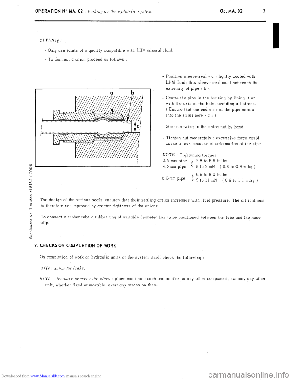
I To connect a union proceed as follows :
- Position sleeve-seal (( a u lightly coated with
L,HM fluid; this sleeve seal must not reach the
extremity of pipe (( b )).
- Centre the pipe in the housinq by lininq it up
with the axis of the hole, avoidinq all stress.
( Ensure that the end u b )I of the pipe enters
into the smali bore C< c )> j.
Start screwing in the union nut by hand.
- Tiqhten nut moderately : excessive force could
cause a leak because of deformation of the pipe
NOTE Tiqhteninq torques :
3.5 -mm pipe t 5.8 to 6 6 ft lbs
4 5 mm pipe 5 8 to 0 mN ( 0.8 to.0 9 ‘1 kg )
6 6 to 8 0 ft.lbs
6. O-mm pipe
1
9 to 11 mN (0 9 to 1 1 m.kg ) c ) Fittilzg :
I Only use joints of a quality compatible with LHM mineral fluid.
The design of the various seals ensures that their sealing action increases with fluid pressure The oiltiqhtness e
is therefore not improved by greater tiqhtness of the unions
2 To connect a rubber tube a rubber rinq of suitabie diameter has to be positioned between thr, tube and the hose
:
E clip.
0
x
a
A 9, CHECKS ON COMPLETION OF WORK
On completion of work on hydraulic units or the system itself check the followinq :
h) ‘1’11~ C./CJ~~~IIC-C, I~c,lrt,c,c,rt I/J<
pipvs : pipes must not touch one another or any other component, nor may any other
unit, whether fixed or movable, exert any stress on them.
Page 143 of 394
Downloaded from www.Manualslib.com manuals search engine 11. Switch on throttle butterfly spindle ( maximum power function ) ( DIAGRAM 11 )
- Disconnect the E.C.U.
- Using a battery operated ohmmeter, check there is no resistance between terminals (( 3 H and (( 18 )) of the
multiple connector board, with the accelerator pedal fully depressed
t 12. E.C.U. : ( DIAGRAM 12) +
s
*
i :
2 - Visually check the condition of the terminals ( male connectors on the E-C U., and female connectors
on the multiple connector socket ).
- With the engine running, tap lightly on the E.C.U., to detect any possible defect in the soldering ( dry
joints ).
Page 158 of 394
Downloaded from www.Manualslib.com manuals search engine OPERATION No MA. 210-O : (.h(~~-ki/lg n~lc/ c~tlj~~s/irtg the igrlitiorl Op. MA. 210-O 3
1. Checking the condition of the contacts :
Check the voltage drop across the contacts ( contacts closed ) under a voltage of 12 volts. using a test-bench.
The voltage drop should be 0.2 volts max.
I
2. Checking the centrifugal advance curve :
a) Note the advance in stages for steadily increasing engine speeds from 0 to 3000 rpm. and for steadily
decreasing engine speeds from 3000 rpm to 0, t~/~kjj/$ SII~L’
the irirwasc, or d~,rrc~as~’ is c-o~~ti~ootl.5.
These points must fall within the shaded area of the curve.
b) To a certain extent. it is possible to correct the advance curve, by altering the tension of the springs for
the centrifugal weights To obtain this condition, slightly bend (
iv t/1(, np1)ro/)riotc, ciirectioll J the securing
brackets for the springs, or replace them.
IY NOTE : If luminous spots are produced outside the four normal positions at speeds under 3000 rpm. make
5 sure the contact points are clean and if necessary make sure the test-bench battery is fully charged. before
U replacing the contact-breaker unit. the spring of which may have weakened.
7
co
m
r 3. Checking the spark regularity :
2
Whatever the speed of rotation, the angular difference of the four opening positions of the points must n.ot
3 exceed lo I 21n.xint~lm r/In/ oj distributor : 3250 I./)NI. c,.vcc,pt I)l’(.lit,t.tt~K 525 06X A : 2750
r/m 1,
c
E
!i
a
z 4. Ch k’ ec rng and adjusting the dwell angle :
Run the distributor at a steady speed, and check that the dwell angle is equal ;o 55’ ? 2”30’. If this is not the
case, adjust the contact breaker to obtain this condition.
5. Checking the ignition condenser :
With the contact points open. measure the capacity of the condenser; This value must be 0.30 i 0.03 wF.
If this is not the case. replace the condenser.
6. Check the vacuum advance curve :
This check is carried out at a constant rpm of 200, with no centrifugal advance.
Check the points of the increasing curve. and the decreasing curve. If the vacuum capsule has n hathcr.
it will be necessary to blank it off during this check.
Page 163 of 394
Downloaded from www.Manualslib.com manuals search engine OPERATION No MA. 210-O Q : C.‘/)c,r&iug nnrt nrljtlsliug I110 c~t~~clro~~ic igrliliorl sj’slvnv. Op. MA. 210-O a 3
1. Adiust star-point gop : 0.3 to 0.5
mm
2. Check the centrifugal advance curve :
a) Note the advance in stages for steadily increasing engine speeds from 0 to 3000 rpm and for steadily decreasing
engine speeds from 3000 rpm to 0. making sure the increase or decrease is continuous. These points must fall
within the shaded area of the curve.
b ) To a certain extent. it is possible to correct the advance curve. by altering the tension of the springs for the
z centrifugal weights To obtain this condition slightly bend (
irr I~V nppropriate clirvcliou ) the securing brackets
6 for the springs. or replace them.
ot,
43
a
3
E
E 3. Checking the symmetry of the star-points :
-z
0
IFi
The angular positioning of the 4- star-points must be the same to within 1”. whatever the speed of the engine.
4. Checking the vacuum advance curve :
This check is carried out at a constant 200 rpm. with no centrifugal advance.
Check the points for the increasing curve, then the decreasing curve.
If the vacuum capsule has a breather, it will be necessary to blank it off during the’test.
Page 201 of 394
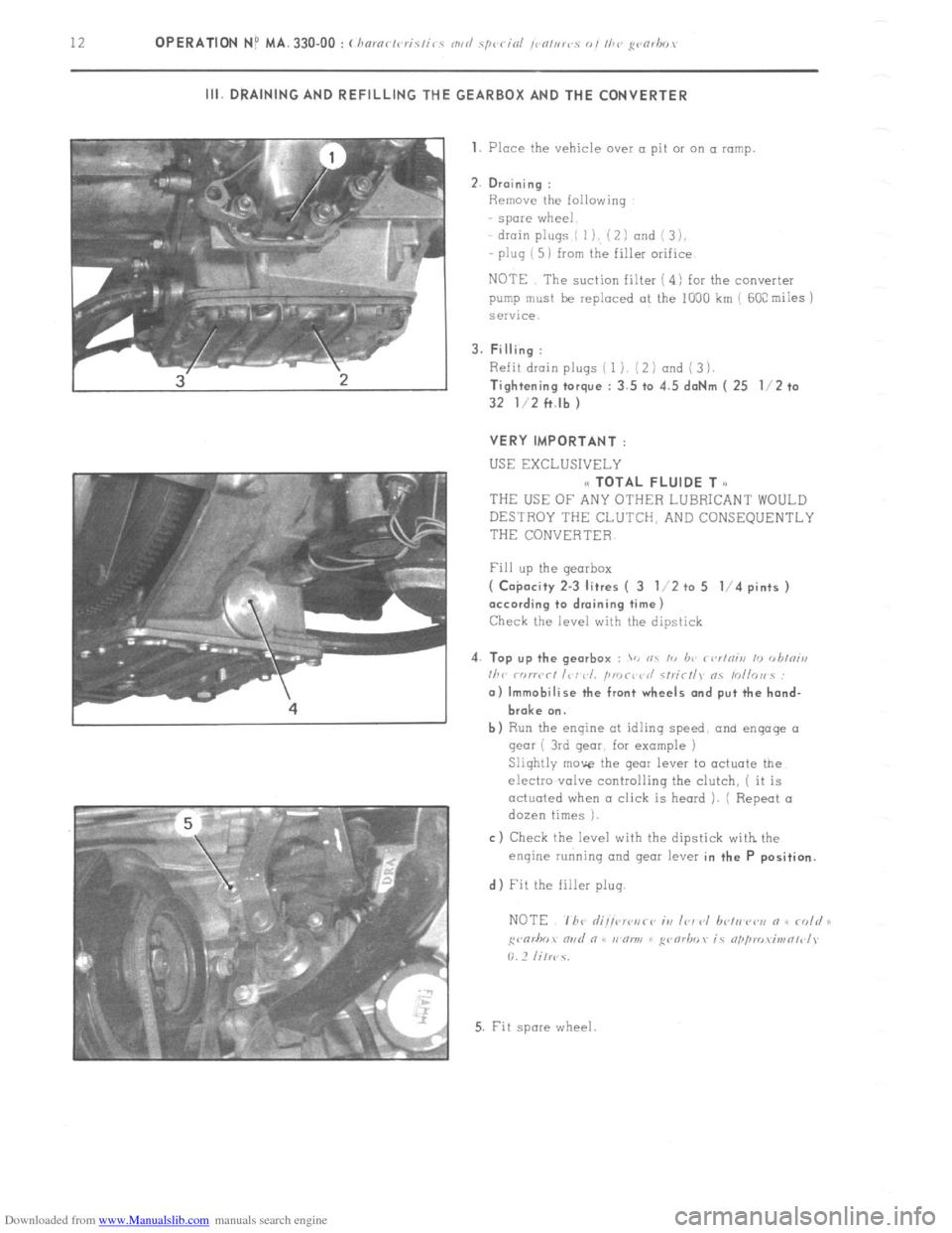
Downloaded from www.Manualslib.com manuals search engine 12 OPERATION NP MA. 330.00 : (haro? gvmhr,, III. DRAINING AND REFILLING THE GEARBOX AND THE CONVERTER
1. Place the vehicle over a pit 01 on a ramp
2. Draining :
Remove the following
spare wheel
drain plugs ( I), ( 2 I and i 3 ),
plug ( 5) from the filler orifice
NOTE The suction filter ( 4) for the converter
pump must be replaced at the 1000 km ( 60C miles j
service.
3. Filling :
Refit drain plugs ( 1). (2 1 and ( 3 1.
Tightening torque : 3.5 to 4.5 daNm ( 25 l/2 to
32 l/2 ft.lb )
VERY IMPORTANT :
USE EXCLUSIVELY
(< TOTAL FLUIDE T o
THEUSEOFANYOTHERLUBRICANTWOULD
DESTROY THE CLUTCH, AND CONSEQUENTLY
THE CONVERTER
Fill up the gearbox
( Co$acity 2-3 litres ( 3 l/2 to 5 l/4 pints )
according to draining time)
Check the level with the dipstick
4. Top up the gearbox :
> nc I<, b<’ r<,r/niii 10 <,hini,,
I/><,
broke on.
b) Run the engine at idlinq speed, and engage 01
gear ( 3rd gear, for example )
Slightly move the gear lever to actuate the
electro .valve controlling the clutch, ( it is
actuated when a click is heard ). ( Repeat a
dozen times ).
c) Check the level with the dipstick with the
enqine running and gear lever in the P position.
d) Fit the filler plug.
5. Fit spore wheel
Page 228 of 394
Downloaded from www.Manualslib.com manuals search engine 2 OPERATION No MA. 390-O : Checking the hydra&c conponmts on the.uehicle
f Mnnual sirrrin~ uehicles J CHECKS
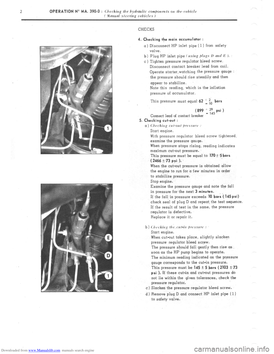
4. Checking the main accumulator : a) Disconnect HP inlet pipe ( 1) from safety
valve.
b) Plug HP inlet pipe fusing p[u~s D
and E ). : c ) Tighten pressure regulator bleed screw.
Disconnect contact breaker lead from coil.
Operate storter,watching the pressure g”“ge :
the pressure should rise steadily and then
appear to stobilize.
Note this reading, which is the inflation
pressure of acc”mulator.
This preksure must equal 62 ‘, To
bars
(899 IE,psi) Corned lead of contact breaker
5. Checking cut-out :
a) Checking cut-out ~TPSSU~~~ : Start engine.
With pressure regulator bleed screw tightened,
examine the pressure gauge.
When pressure stops rising, reading indicates
maximum cut-out pressure.
This pressure m”st be equal to
170 t’5 bars
(2466 ?,73 p:i ). When the c”t-o”t pressure is obtained allow
the engine to nrn for a few minutes in order
to stabilize pressure.
Stop engine.
Examine the pressure gauge and note the fall
in pressure for the next 3
minutes. If the fall in’pressure exceeds
10 bark 4 145psi) check seai of plug D and repeat, the test sequence.
If the result of test is the some, the pressure
regulator is defective,
Replace it 01 repair it.
When cutout takes place, slightly slacken
pressure regulator bleed screw.
The pressure should fall gently then rise (IS~.
soon (IS the HP pump begins to operate.
The minimum reading indicated on tbe pressure
gauge corresponds to the cut-in pressure.
This pressure must be 145 +,5 bars
(2103 ?,73
psi ). If these cut-in and cot-out pressures do
not lie within the given tolerances, check the
pressure regulator.
c) Slacken the pressure regulator bleed screw.
d) Remove plug D and connect HP inlet pipe ( 1)
to safety valve.
Page 229 of 394
Downloaded from www.Manualslib.com manuals search engine OPERATION No MA. 390-O : Checkin
P the hydraulic componm~s on the ucbicle Op. MA. 390-O 3
f Mama sleeting wbi&s I
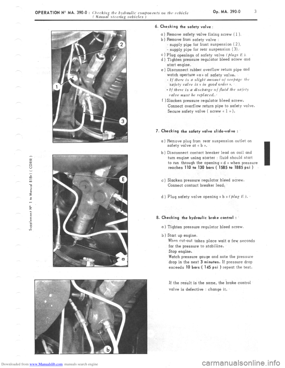
6. Checking the safety valve :
=I
bl
Cl
dl
Remove safety v&e fixing screw ( 1 ).
Remove from safety valve :
supply pipe for front suspension (2 ),
- supply pipe for rem suspension (3):
Plug openings of safety valve ( pIugs E J.
Tighten pressure regulator bleed screw
and
start engine.
Disconnect rubher overflow return pipe and
watch aperture ~a>> of safety valve.
- I/ Iherr is a slight c7moa,,t 0, sHymge thr
sa/cty ~dve is s in good ordrv n.
el
-If thrr~ is a discharge of fluid the sniw
dw must be rqlacrd..
f ) Slacken pressure regulator bleed screw-
Conned overflow return pipe to safety valve.
Secure safety valve ( screw (( 1 a) 1.
7. Checking the safety valve slidevolve :
a) Remove plug from rem suspension outlet on
safety v&e at G b >a.
b ) Disconnect contact breaker lead on coil and
turn engine using stmter : fluid should start
to run through the opening a d N when pressure
reaches
1lLl +o 130 bars ( 1585 to 1885 psi )
c) Slacken pressure regulator bleed screw.
Connect contact breaker lead.
d ) Plug safety valve opening u b )) (plug E ).
8. Checking the hydraulic brake contml :
m ) Tighten pressure regulator bleed screw.
b) Start up engine.
When cut-out takes place wait a fen: seconds
for the pressure to stobilize.
Stop engine%
Watch pressure gauge and note the pressure
drop in the next 3
minutes. If pressure drop
exceeds 10 bors*( 145 psi ) repeat the test.
If the re< is the same. the broke control
valve is defective : change it.
Page 257 of 394
Downloaded from www.Manualslib.com manuals search engine OPERATION No MA. 430-O : Checking md ndjusting the suspcusion and its control. 06. MA. 430-O i
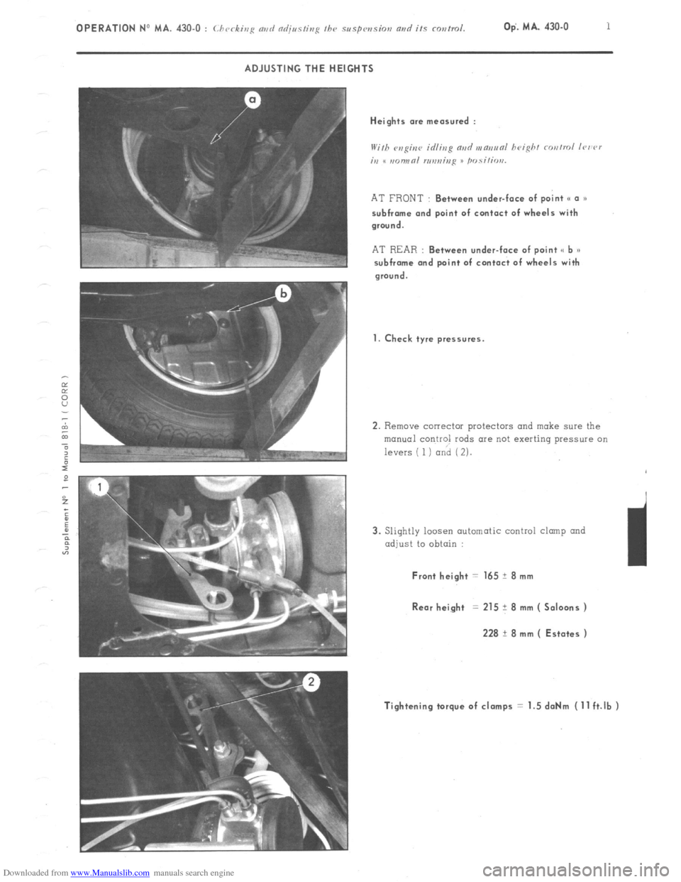
ADJUSTING THE HEIGHTS
AT FRONT : Between under-face of point (c o ))
subfrome ond point of contoct of wheels with
ground.
AT REAR : Between under-face of point <( b a)
subfrome ond point of contact of wheels with
ground.
1. Check tyre pressures.
2. Remove corrector protectors and make sure the
manual control rods are not exerting pressure on
levers ( 1) and ( 2).
3. Slightly loosen automatic control clump and
adjust to obtain :
3
Front height = 165 ? 8 mm
Rear height = 215 ? 8 mm ( Saloons )
228 t 8 mm ( Estates )
Tightening torque of clomps = 1.5 doNm (11 ft.lb )
Page 285 of 394
Downloaded from www.Manualslib.com manuals search engine OPERATION No MA. 453=0 : Ch J k’ ( c zng and adjjusfing thr hydraulk brake rontrol Op. MA. 453-O 3
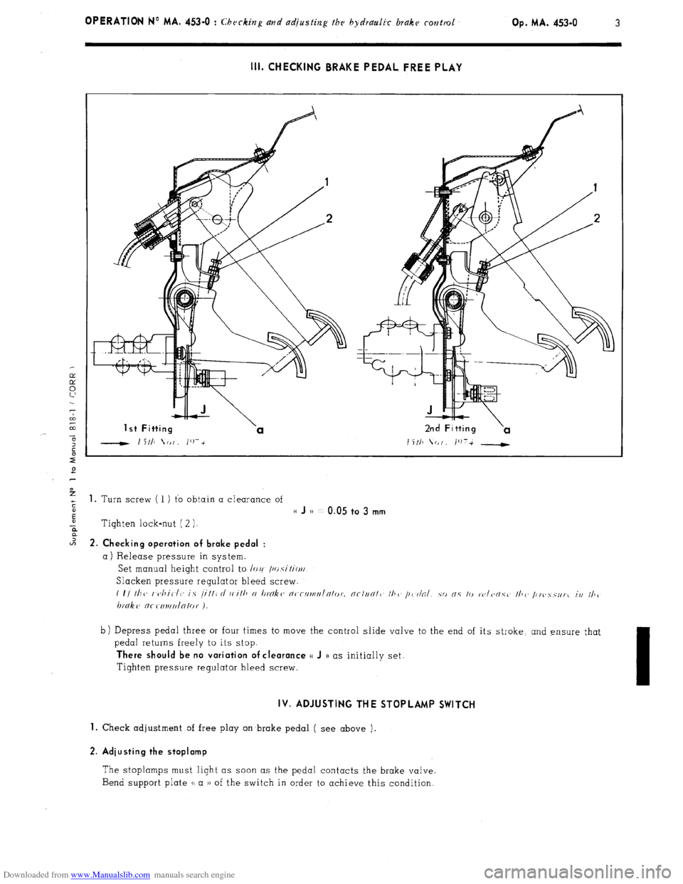
III. CHECKING BRAKE PEDAL FREE PLAY
1 st Fitting 2nd Fitting
1 5 111 (I I /‘)7-t __t i%
+ 1. Turn screw ( 1 ) to obtain a clearance of
s
E
(( J )) ~~ 0.05 to 3 mm
-ii Tighten lock-nut ( 2 ).
2 2. Ch k’ ec Ing operation of brake pedal :
a) Release pressure in system.
Set manual height control to /or! /~~.s\‘itio~/
Slacken pressure regulator bleed screw.
( I/ Ill<, I <~/liClC~ is /ill1 rl i, ill, N I~tYlk~~ n~-rllrlll,Inlo,~. nc/un/1 II?<, /I< r/al.
hnke nr c111uu/n/0,. ).
b) Depress pedal three or four times to move the control slide valve to the end of its stroke, and ensure that
pedal returns freely to its stop.
There should be no variation of clearance o J )) as initially set.
Tighten pressure regulator bleed screw.
IV. ADJUSTING THE STOPLAMP SWITCH
1.
Check adjustment of free play on brake pedal ( see above ).
2. Adiusting the stoplamp
The stoplamps must light as soon as the pedal contacts the brake valve.
Bend support plate u a )) of the switch in order to achieve this condition.