Citroen CX 1982 1.G Workshop Manual
Manufacturer: CITROEN, Model Year: 1982, Model line: CX, Model: Citroen CX 1982 1.GPages: 394
Page 111 of 394
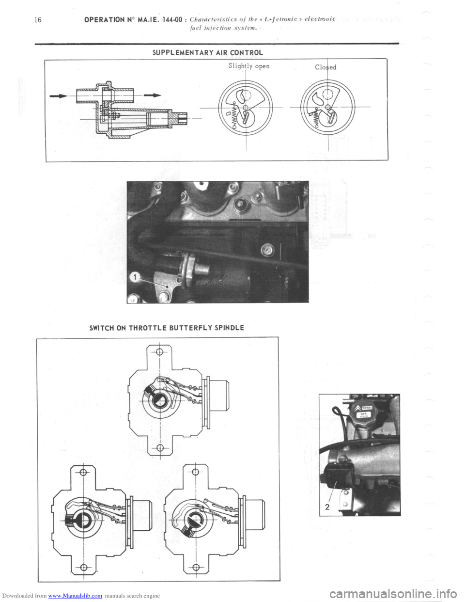
Downloaded from www.Manualslib.com manuals search engine SUPPLEMENTARY AIR CONTROL
SWITCH ON THROTTLE BUTTERFLY SPlkDLE
Page 112 of 394
Downloaded from www.Manualslib.com manuals search engine OPERATION No MA.IE. 144-00 : Chnract~~ristics o/ the H I,-jctrortic P dectrnr~ir
/i/c,1 iujcctim splcm. Op. MA.IE. 144-00 17
SUPPLEMENTARY AIR CONTROL ( 1 ) :
I’ / -...’ , _, ._,, ! .’ ! . .
At idling speed and when cold, the engine must produce more torque so as to counteract increased resistance
caused by friction. In addition to an enriched air fuel mixture, the engine also needs, when starting from cold
and during the warming-up period, to be supplied with supplementary air. The E.C.U. compensates for this
supplementary air by providing more fuel; the engine therefore has a larger amount of mixture at its disposal
to reach normal running temperature. The supplementary air control fitted in parallel with the throttle butterfly
supplies the supplementary air. The supplementary air control is heated only when the engine is running, and
its heater winding is supplied electrically as long as the ignition is switched on.
The location of the supplementary air control ‘on the engine block was selected for its good heat transfer charac-
teristics, and so as to subject the unit to the changing ambient temperature of the engine.
The opening section of the supplementary air control is automatically .adjusted according to the temperature, so
that the required idling speed is maintained regardless of engine temperature. When the latter increases, the air
channel is gradually reduced, until it is completely closed when the coolant temperature reaches approximately
+ 60” C. ->.:.. .-. : --.
,
The supplementary air control is situated at a representative spot fo.r engine running temperature. A bi-metal
spring actuates a rotary valve thereby altering the size of the air passage. Electric heating has the advantage
of allowing the. supplementary air to be adjusted at pre-set times. SWITCH ON THROTTLE BUTTERFLY SPINDLE :
,‘1 3 >_
The switch on the throttle butterfly spindle contains two contacts the idling speed contact, and the.full load contact.
The control contact, which.slides along a slot, closes the idling speed contact or the full load contact for a given
position of ‘the butterfly. The’ E.C.U. analyses the signals received so as to adjust the duration of injection.
Page 113 of 394
Downloaded from www.Manualslib.com manuals search engine ELECTRIC PETROL PUMP
The petrol pump is of the multi roller-vane type, driven by an electric motor which is energized as long as the
ignition is switched on. The rotor, which is fitted eccentrically in the pump housing, has metal roller vanes in
grooves around t.he periphery which, when they are forced outwards under the action of the centrifugal force, ensure
the system-is sealed.
Fuel is drawn into the cavities which,appear in between the roller-vanes, and is then forced into the injection
piping.
The electric motor is submerged’ in fuel. However, there .is no fire risk, since there is never any combustible
mixture in the pump housing. The pump supplies more fuel than the engine consumes under full load, so that
there is always sufficient pressure in the fuel system, whatever the engine speed. Excess fuel flows back to
the tank.
Once the ignition is on, the pump operates at the same time as the starter motor. Once the engine is running, the
airflow sensor energizes the pump.
Thanks to this type of.system, if an injector is faulty ( leaks ) the cylinder in question cannot be flooded if one
has ommitted to switch the ignition off. PETROL FILTER (1) :
A fuel filter, fitted between the pump and the injectors, prevents any impurities from reaching the injectors. PETROL PRESSURE REGULATOR ( 2 ) :
The fuel pressure is maintained constant by the pressure regulator. It comprises a metal housing
is a diaphragm., One side of the dipphragm.is subjected to the fuel under pressure, and the other 2
to the action of a calibrated spring. inside which
side is subjected
When the fuel pressure is in excess of 2 bars ( 29 psi ), the diaphragm lifts and allows fuel to flow back to the
tank.
The pressure provided by the regulator is pre-adjusted at the factory. The chamber on the side of the spring is
connected via a flexible pipe to the inlet manifold. Therefore, the difference between the pressure in the inlet
manifold and that of the fuel is maintained constant.
For any engine load, the drop in pressure at the injectors is therefore the same.
Page 114 of 394

Downloaded from www.Manualslib.com manuals search engine Op. MA.IE. 144.00 19
/
One-way valve
Safety valve
PRESSURE REGULATOR
Id.17
t Return to tank
Page 115 of 394
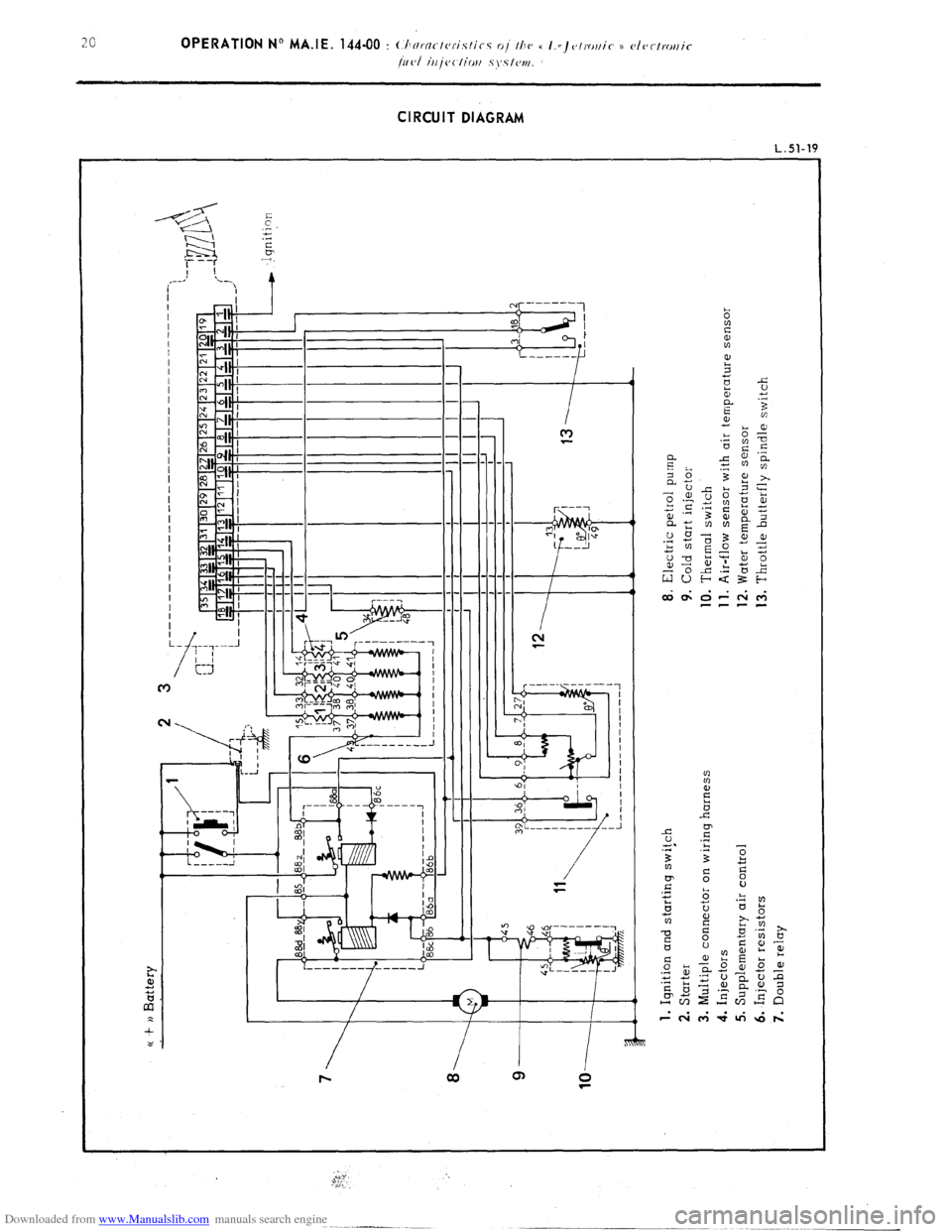
Downloaded from www.Manualslib.com manuals search engine CIRCUIT DIAGRAM
L.Sl-19
I III I
I
--_
------
-- ---- 1 r---7
2, 0 ;,”
1 ---J
::- ----
---- r---~
“‘i
Page 116 of 394
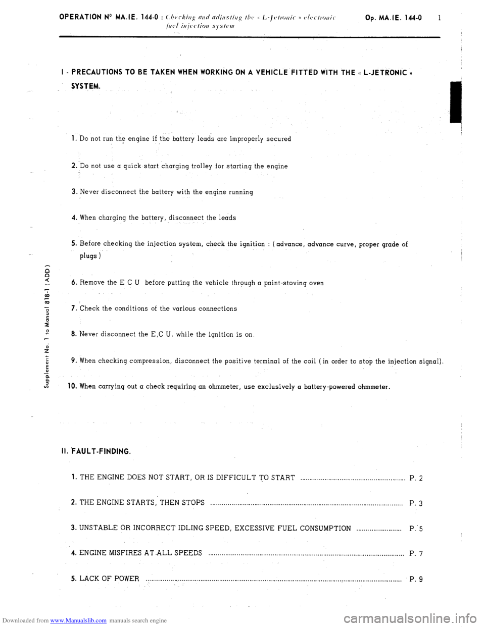
Downloaded from www.Manualslib.com manuals search engine Op. MA.IE. 144-O 1 I - PRECAUTIONS TO BE TAKEN WHEN WORKII;(G ON A VEHICLE FITTED WITH THE (t L-JETRONIC n
SYSTEM.
1.
Do not run the engine if the battery leads are improperly secured
2. Do not use a quick-start charging trolley for starting the engine
3. Never disconnect the battery with the engine running
4. When charging the battery, disconnect the leads
5. Before checking the injection system, check the ignition : (advance, advance curve, proper grade of plugs 1
6. Remove the E C U before putting the vehicle through a paint-stoving oven
7. Check the conditions of the various connections
8. Never disconnect the E,C U. while the ignition is on
9. When checking compression, disconnect the positive terminal of the coil (in order to stop the injection signal). 10.
When carrying out a check requiring an ohmmeter, use exclusively a battery-powered ohmmeter. II. FAULT-FINDING.
1. THE ENGINE DOES NOT START, OR IS DIFFICULT TO START . . . . . . . . . . . . . . . . . . . . . . . . . . . . . . . . . . . . . . . . . . . . . . . . . . . . . . . . P. 2
2. THE ENGINE STARTS, THEN STOPS . . . . . . . . . . . . . . . . . . . . . . . . . . . . . . . . . . . . . . . . . . . . . . . . . . . . . . . . . . . . . . . . . . . . . . . . . . . . . . . . . . . . . . . . . . . . . . . . . . . . . . P. 3
3. UNSTABLE OR INCORRECT IDLING SPEED, EXCESSIVE FUEL CONSUMPTION ........................ P:5
-4. ENGINE MISFIRES AT .ALL SPEEDS ........................................................................................................
P. 7
5. LACK OF POWER . . . . . . . . . . . . . . . . . . . . . . . . . . . . . . . . . . . . . . . . . . . . . . . . . . . . . . . . . . . . . . . . . . . . . . . . . . . . . . . . . . . . . . . . . . . . . . . . . . . . . . . . . . . . . . . . . . . . . . . . ................ P. 9
Page 117 of 394
![Citroen CX 1982 1.G Workshop Manual Downloaded from www.Manualslib.com manuals search engine 2 OPERATION No MA.IE. 144-O : (:I ’ k’ J( c /r/g Ulld ufijljr,slirlg rhc (i l~-]ct,.o~lic )) clectNNlic
/IIVI inicclion system.
1 -
THE Citroen CX 1982 1.G Workshop Manual Downloaded from www.Manualslib.com manuals search engine 2 OPERATION No MA.IE. 144-O : (:I ’ k’ J( c /r/g Ulld ufijljr,slirlg rhc (i l~-]ct,.o~lic )) clectNNlic
/IIVI inicclion system.
1 -
THE](/img/9/4131/w960_4131-116.png)
Downloaded from www.Manualslib.com manuals search engine 2 OPERATION No MA.IE. 144-O : (:I ’ k’ J( c /r/g Ulld ufijljr,slirlg rhc (i l~-]ct,.o~lic )) clectNNlic
/IIVI inicclion system.
1 -
THE ENGINE DOES NOT START,
OR IS DIFFICULT TO START.
I
P.T.O.
Page 118 of 394

Downloaded from www.Manualslib.com manuals search engine
Page 119 of 394

Downloaded from www.Manualslib.com manuals search engine OPERATION N” MA.IE. 144-0 : (.I I(“ i//g N//f/ nrl;clslir,g Ill<’ 0 I.-j<~/ro/,ic 1)
/I/(,/ illj(‘c-lior, sy.~lvm.
I
2-
?HE ENGINE STARTS, THEN STOPS
Page 120 of 394

Downloaded from www.Manualslib.com manuals search engine :::::::::s.gzjg:
:“’ : : : ,::::y,.,
- ,...,. ., ,. .,
T,.,,; !f;;.’ ;:.,
- ‘: .,.,
; +:“z”
, :“...
, .I.
~ i.:m-,
i: .&l
:::... :,
: ..” :,..
::