Downloaded from www.Manualslib.com manuals search engine THIS STEERING SYSTEM HAS THREE DIFFERENT FUNCTIONS
- Power operation i rc,d/ic-/ici// 0 I .~/I c,r-i/lg-o /Io.c,/ c’//or/ /
Stiffeninq of the steerinq as a function of the speed of the vehicle f s////it-ic,r/t /<,(,I o/ 11~1 c/c,c~ri/t.cq r/~llc(,I I//JNI(,I or
lhc, 1 cjhicle spc,c~d )
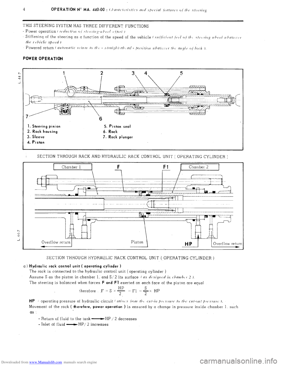
1. Steering pinion 5. Piston seal
2. Rack housing 6. Rack
3. Sleeve 7. Rack plunger
4. Piston
I SECTION THROUGH RACK AND HYDRAULIC RACK CONTROL UNIT ( OPERATING CYLINDER )
SECTION THROUGH HYDRAULIC RACK CONTROL UNIT ( OPERATING CYLINDER )
a) Hydraulic rack control unit ( operating cylinder )
The rack is connected to the hydraulic control unit ( operating cylinder )
Assume S as the piston in chamber 1, and S/ 2
its surface ( ns dcjsiguvd iu c-hmvhc 1’ 2 J.
The steering is balanced when forces F and Fl exerted on each face of the piston are equal
therefore F = S x F =Fl +x HP
HP 1 operatinq pressure of hydraulic circuit f mist s l‘ront /hc r-r/-iit /I,,( s.5~1’~~ lo fhc cf4I-r)ul /~r~~.~.s~ir~~ J.
Movement of the rack ( therefore, power operation ) is ensured by a change in pressure inside chamber 1, such
as
I Return of fluid to the tank -HP / 2 decreases
- Inlet of fluid -HP/ 2 increases
Downloaded from www.Manualslib.com manuals search engine d
m
.-
0
2
f Op. MA. 440-00
7 -
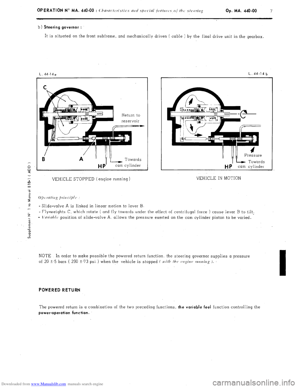
b) Steering governor :
It is situated on the front subframe, and mechanically driven ( cable ) by the final drive unit in the gearbox.
Ei A ”
VEHICLE STOPPED (engine running)
L.44-14b
I/ /II I Pressure
IL Towards
HP cam cylinder
VEHICLE IN MOTION
* Slide-valve A is linked in linear motion to lever B
- Fly-weights C, which rotate ( and fly towards under the effect of centrifugal force ) cause lever B to tilt.
=
L'nrioblc, position of slide-valve A, allows the pressure exerted on the cam cylinder piston to be varied.
NOTE In order to make possible the powered return function. the steerinq governor supplies a pressure
of 20 i-15 bars ( 290 +173 psi ) when the vehicle is stopped f 11
i/F /hc cwgir/e wt/t~iv.g i.
I
POWERED RETURN
The powered return is a combination of the two preceding functions, the variable feel function controlling the
power-operation function.

