coolant Citroen CX 1982 1.G Workshop Manual
[x] Cancel search | Manufacturer: CITROEN, Model Year: 1982, Model line: CX, Model: Citroen CX 1982 1.GPages: 394
Page 88 of 394
Downloaded from www.Manualslib.com manuals search engine II. cx 2000
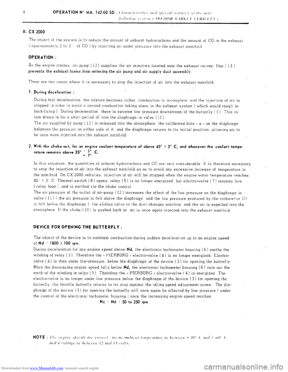
The object of the system is t3 reduce the amount of unburnt hydrocarbons and the amount of CO in the exhaust
( approximately 2 to 3
of CO ) by injectinq air under pressure into the exhaust manifold
OPERATION :
As the enqine rotates air pump ( 12) supplies the air injectors located near the exhaust valves: flap ( 13 )
prevents the exhaust fumes from entering the air pump and air supply duct assembly.
There are two cases where it is necessary to stop the injection of air into the exhaust manifold.
1. During deceleration :
Durinq fast deceleration. the mixture becomes richer combustion is incomplete and the injection of air is
stopped in order to avoid a second combustion takinq
place in the exhaust system ( which would result in
back-firinq ) Durinq deceleration there is extreme low pressure downstream of the butterfly ( 1 ). This in
turn draws in for a short period of time the diaphragm in valve ( 11 )
The air supplied by pump ( 12 ) is released into the atmosphere, the calibrated hole (( a 1) on the diaphragm
balances the pressure on either side of it and the diaphraqm returns to its initial position, allowinq air to
be once more injected into the exhaust manifold
2. With the choke out, for an engine coolant temperature of above 45’ + 3’ C, and whenever the coolant tempe-
rature remains above 35’ i “,I C.
In this situation the quantities of unburnt hydrocarbons and CO are very considerable It ‘is therefore necessary
to stop the injection of air into the exhaust manifold so as to avoid any excessive increase of temperature in
the manifold. On CX 2000 vehicles, injkction of air will be stopped when the enqine water temperature reaches
45” + 3- C Thermal switch ( 8 ) opens, relay ( 9 )
1s no lonqer enerqized. but electro-valve ( 7 ) remains live
( relay lead ). and is earthed via the choke control
The air pressure at the outlet of air-pump ( 12 )
increases the effect of the low pressure on the diaphraqm in
valve ( 11 ) ( the air pressure is felt above the diaphraq,m, and the low pressure produced by the carburettor (2)
is felt below the diaphraqm ). the slidinq valve in the duct chanqes position and the air is expelled into the
atmogphere If the choke ( 10) is pushed back in air is once again injected into the exhaust manifold
DEVICE FOR OPENING THE BUTTERFLY :
The object of the device is to maintain combustion during sudden deceleration up to an enqine speed
of
Nd 7 1800 + 100 rpm.
Durinq deceleration for any enqine speed above Nd, the electronic tachometer housinq ( 6 ) earths the
windinq of relay ( 5) Therefore the H PIERBURG 1) electro-valve ( 4) is no lonqer enerqized. Electro-
valve ( 4) is then under low-pressure, below the diaphragm of the device ( 3 ) for opening the butterfly
When the decreasinq enqine speed falls below
Nd, the electronic tachometer housing (6 ) cuts out the
earth of the winding in relay ( 5) Therefore the (( PIERBURG )) electro-valve ( 4) is enerqized The
electro-valve is no lonqer under low pressure below the diaphraqm of the device (3) for openinq the
butterfly the throttle butterfly returns to it s stop aqainst the idlinq speed adjustment screw. The dia-
phraqm of the device (3) for openinq the butterfly will once aqain be affected by low pressure ( under
the control of the electronic tachometer housing ) once the increasing engine speed reaches
NC ~ Nd t 50 to 250 rpm
Page 89 of 394
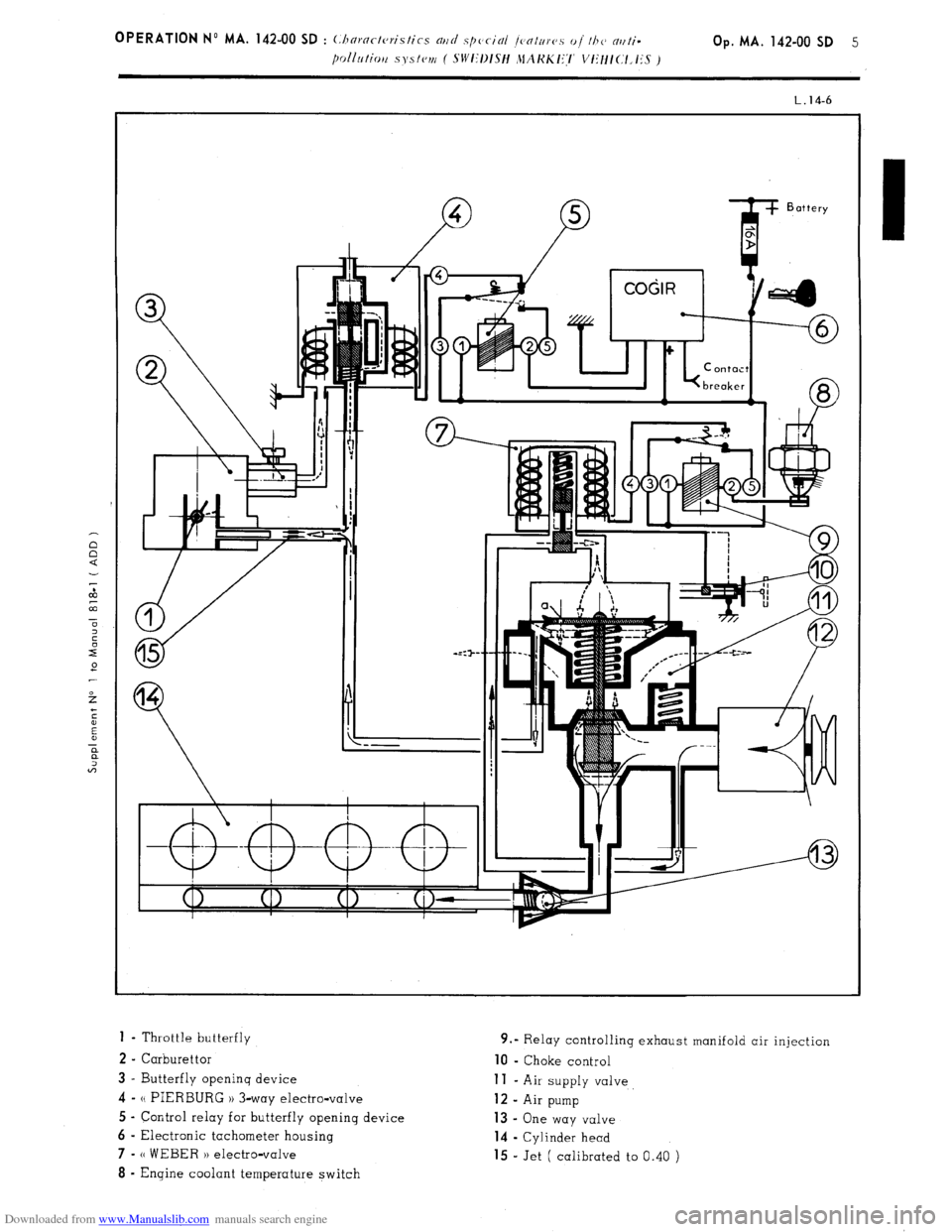
Downloaded from www.Manualslib.com manuals search engine 1 - Throttle butterfly
2 - Carburettor
3 - Butterfly openinq device 4-
N PIERBURG 1) 3-way electro-valve
5 - Control relay for butterfly opening device
6 - Electronic tachometer housing 7-
(( WEBER H electro-valve 8
- Engine coolant temperature switch 9.” Relay controlling exhaust manifold air injection 10
- Choke control
11 - Air supply valve 12
- Air pump 13 -
One way valve
14 - Cylinder head
15 - Jet ( calibrated to 0.40 )
Page 109 of 394
Downloaded from www.Manualslib.com manuals search engine COLD START INJECTOR
When the engine is cold, fuel settles on the inlet distribution chamber, and on the cylinder walls. Therefore, the
quantity of fuel which mixes with the inlet air is smaller than in an engine which has reached normal running
temperature. The mixture thus obtained will not ignite.
The cold-start injector enriches the mixture in each inlet duct by vaporizing fuel in the inlet manifold. However,
it only comes into operation when the starter motor is actuated, and when a thermal switch located inthe engine
coolanthas simultaneously closed the circuit.
‘A helicoidal spring compresses the mobile core of,the electro-magnet and its seal fuel cannot pass through.
When the magnetic core is attracted, the injector seat is freed-off, the fuel flows past the core. and.reached the
spiral effect injector, which injects the fuel, simultaneously giving it a spiral motion, and vaporizing it very finely. ‘THERMAL SWITCH
The thermal switch cuts out the operation of the cold-start injector when the temperature of the engine reaches
ir 35” C,,For any temperature below t 35’ C, the thermal switch limits the duration of injection. The maximum
duration is approximately 7.5 sets. at - 20’ C. Duration of injection is reduced as temperature increases
The variation in duration, determined by the thermal switch,.is obtained by means of a bi-metallic strip heated
by an electrical resistance. The bi-metallic strip cuts out the circuit according to the temperature reached after
it has heated for a certain amount of time.
Page 112 of 394
Downloaded from www.Manualslib.com manuals search engine OPERATION No MA.IE. 144-00 : Chnract~~ristics o/ the H I,-jctrortic P dectrnr~ir
/i/c,1 iujcctim splcm. Op. MA.IE. 144-00 17
SUPPLEMENTARY AIR CONTROL ( 1 ) :
I’ / -...’ , _, ._,, ! .’ ! . .
At idling speed and when cold, the engine must produce more torque so as to counteract increased resistance
caused by friction. In addition to an enriched air fuel mixture, the engine also needs, when starting from cold
and during the warming-up period, to be supplied with supplementary air. The E.C.U. compensates for this
supplementary air by providing more fuel; the engine therefore has a larger amount of mixture at its disposal
to reach normal running temperature. The supplementary air control fitted in parallel with the throttle butterfly
supplies the supplementary air. The supplementary air control is heated only when the engine is running, and
its heater winding is supplied electrically as long as the ignition is switched on.
The location of the supplementary air control ‘on the engine block was selected for its good heat transfer charac-
teristics, and so as to subject the unit to the changing ambient temperature of the engine.
The opening section of the supplementary air control is automatically .adjusted according to the temperature, so
that the required idling speed is maintained regardless of engine temperature. When the latter increases, the air
channel is gradually reduced, until it is completely closed when the coolant temperature reaches approximately
+ 60” C. ->.:.. .-. : --.
,
The supplementary air control is situated at a representative spot fo.r engine running temperature. A bi-metal
spring actuates a rotary valve thereby altering the size of the air passage. Electric heating has the advantage
of allowing the. supplementary air to be adjusted at pre-set times. SWITCH ON THROTTLE BUTTERFLY SPINDLE :
,‘1 3 >_
The switch on the throttle butterfly spindle contains two contacts the idling speed contact, and the.full load contact.
The control contact, which.slides along a slot, closes the idling speed contact or the full load contact for a given
position of ‘the butterfly. The’ E.C.U. analyses the signals received so as to adjust the duration of injection.
Page 170 of 394
Downloaded from www.Manualslib.com manuals search engine CHARACTERISTICS
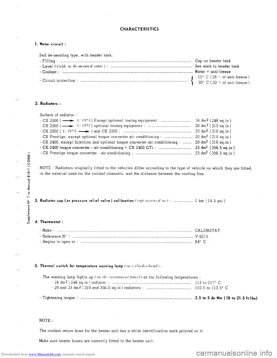
1. Water circuit :
Self de-aerating type, with header tank.
- Filling : . . . . . . . .._................................................................................................................ Cap on header tank
- Level (Cold, iu de-upruled state ) : . . . . . . . . . . . . . . . . . . . . . . . . . . . . . . . . . . . . . . . . . . . . . . . . . . . . . . . . . . . . . . . . . . . . . . . . . . . . See mark in header tank
- Coolant : . . . . . . . . . . . . . . . . . . . . . . . . . . . . . . . . . . . . . . . . . . . . . . . . . . . . . . . . . . . . . . . . . . . . . . . . . . . . . . . . . . . . . . . . . . . . . . . . . . . . . . . . . . . . . . . . . . . . . . . . .. Water + anti-freeze
- Circuit protection : - 15” C ( 28 -: of anti-freeze )
. . . . . . . . . . . . . . . . . . . . .
30” C ( 50 ? of anti-freeze )
2. Radiators :
Surface of radiator :
- cx 2000 ( - 11 1975 ) Except optional towing equipment : . . . . . . . . . . . . . . . . . . . . . . . . . . . . 16 dm2 ( 248 sq.in )
- cx 2000 ( - I/ I’)75 ) optional towing equipment : . . . . . . . . . . . . . . . . . . . . . . . . . . . . . . . . . . . . . . 20 dm2 (310 sq.in)
- cx 2000 ( 1/ 1975 - ) and CX 2200 : . . . . . . . . . . . . . . . . . . . . . . . . . . . . . . . . . . . . . . . . . . . . . . . . . . . . . . . . . . . . . . . . 20 dm2 ( 310 sq.in )
- CX Prestige, except optional torque converter-air conditioning : . . . . . . . . . . . . . . . . . . . . . . . . . . 20 dm2 ( 310 sq.in )
- CX 2400, except Injection and optional torque converter-air-conditioning : . . . . . . . . 20 dm2 (310 sq.in)
- CX 2400 torque converter - air-conditioning + CX 2400 GTi : . . . . . . . . . . . . . . . . . . . . . . . . . . . . . . 23 dm2 ( 356.5 sq.in )
- CX
E Prestige torque converter - air-conditioning : . . . . . . . . . . . . . . . . . . . . . . . . . . . . . . . . . . . . . . . . . . . . . . . . . . . . 23 dm2 ( 356.5 sq.in )
8
-7 NOTE : Radiators originally fitted to the vehicles differ according to the type of vehicle on which they are fitted,
co
_- 03 in the material used for the coolant channels, and the distance between the cooling fins.
T
2 3. Radiator cap (or pressure relief valve) calibration (rap scwzmcl 011) : . . . 1 bar (14.5 psi)
I 4. Thermostat :
- Make : .............................................................................................................................. CALORSTAT
- Reference No : ................................................................................................................ V 6215
- Begins to open at : ........................................................................................................ 84’ C
5. Thermal switch for temperature warning lamp (011 cyli~~d(,r-hc~ad)
- The warning lamp lights up (on the, ivstrrlmeut pnr~(,I) at the following temperatures :
- 16 dm2 (248 sq.in) radiator : . . . . . . . . . . . . .
Ii3 to 117O c
- 20 and 23 dm2 (310 and 356.5 sq.in) radiators : . . . . 110.5 to 113.5” c
- Tightening torque : . . . . . . . . . . . . . . . . . . . . . . . . . . . . . . . . . . . . . . . . . . . . . . . . . . . . . . . . . . . . . . . . . . . . . . . . . . . . . . . . . . . , . . . . . . . . . . . . . . . . . . . .
2.5 to 3 da Nm (18 to 21.5 ft.lbs)
NOTE :
The coolant return hose for the heater unit has a white identification mark painted on it.
Make sure heater hoses are correctly fitted to the heater unit.
Page 172 of 394
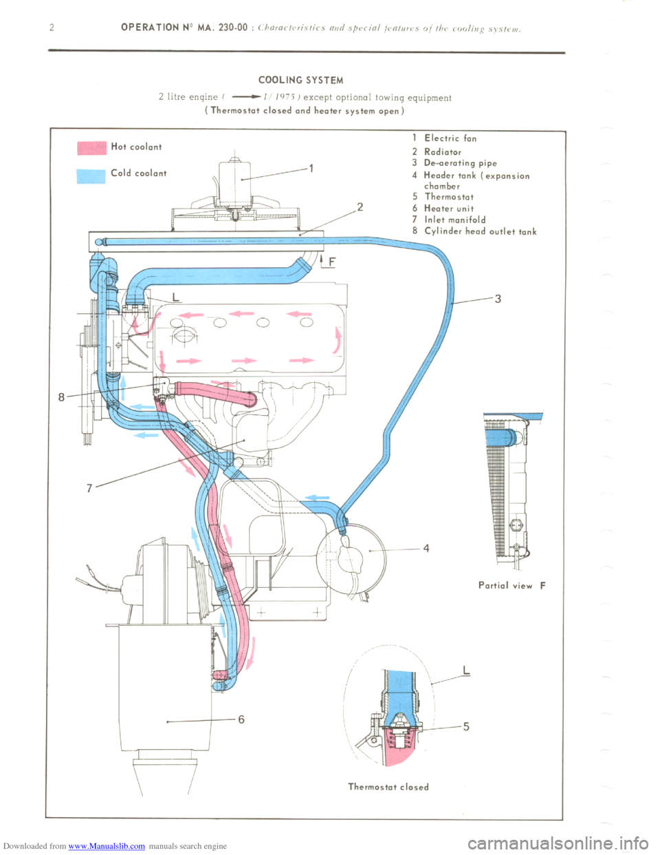
Downloaded from www.Manualslib.com manuals search engine COOLING SYSTEM
L litre enlyne f
-I l’r’i ) except optional towing equipment (Thermostat closed and heater system open)
Hot cool.n+
>Id coolant I Electric fan
2 Radiator
3 De-aerating pipe
4 Header tank (expansion
chamber
5 Thermostat
2 6 Heater unit
7 Inlet manifold
8 Cvlinder head outlet tank
Partial view F
II Thermostot closed
Page 173 of 394
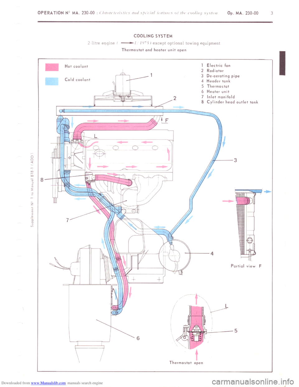
Downloaded from www.Manualslib.com manuals search engine COOLING SYSTEM
/ 11’re e!!qlric
-1 1’1-5 j except oprlonal row,ng equ,pmenr
Thermostat and heater unit open
Hot coolant
Cold coolant I Electric fan
2 Rodiotor
3 De-aerating pipe
4 Header tank
5 Thermostot
6 Heater unit
2 7 Inlet manifold
8 Cylinder heod outlet tonL
-3
Portia1 view F
Thermostat open
Page 174 of 394
Downloaded from www.Manualslib.com manuals search engine -
-
‘F
L
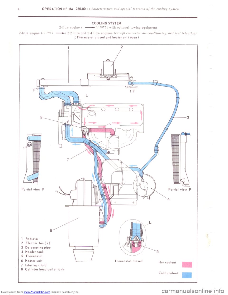
Radiator
! Electric fan ( 5)
I De-oeroting pipe
I Header tank
i Thermostot
I Heater unit
Inlet manifold
i Cylinder head outlet tank Thermostat closed
Hot coolant
Cold coolont -
Page 176 of 394
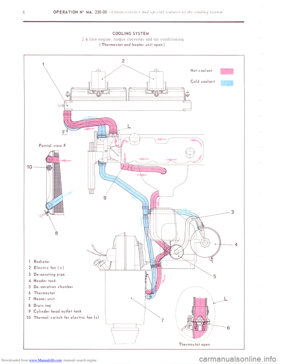
Downloaded from www.Manualslib.com manuals search engine COOLING SYSTEM
2 4 litre engine, torque converter and air conditinninq (Thermostat and heater unit open)
Partial view F
8
1 Radiator
2 Electric fon (5)
3 De-aerating pipe
4 Header tank
5 De-aeration chamber
6 Thermostat
7 Heater unit
8 Drain top
9 Cylinder head outlet tank Cold coolant
,
I-
J1
- 0 Thermal switch for electric fan (s)
l-J 7
6
Thermostat open
Page 177 of 394
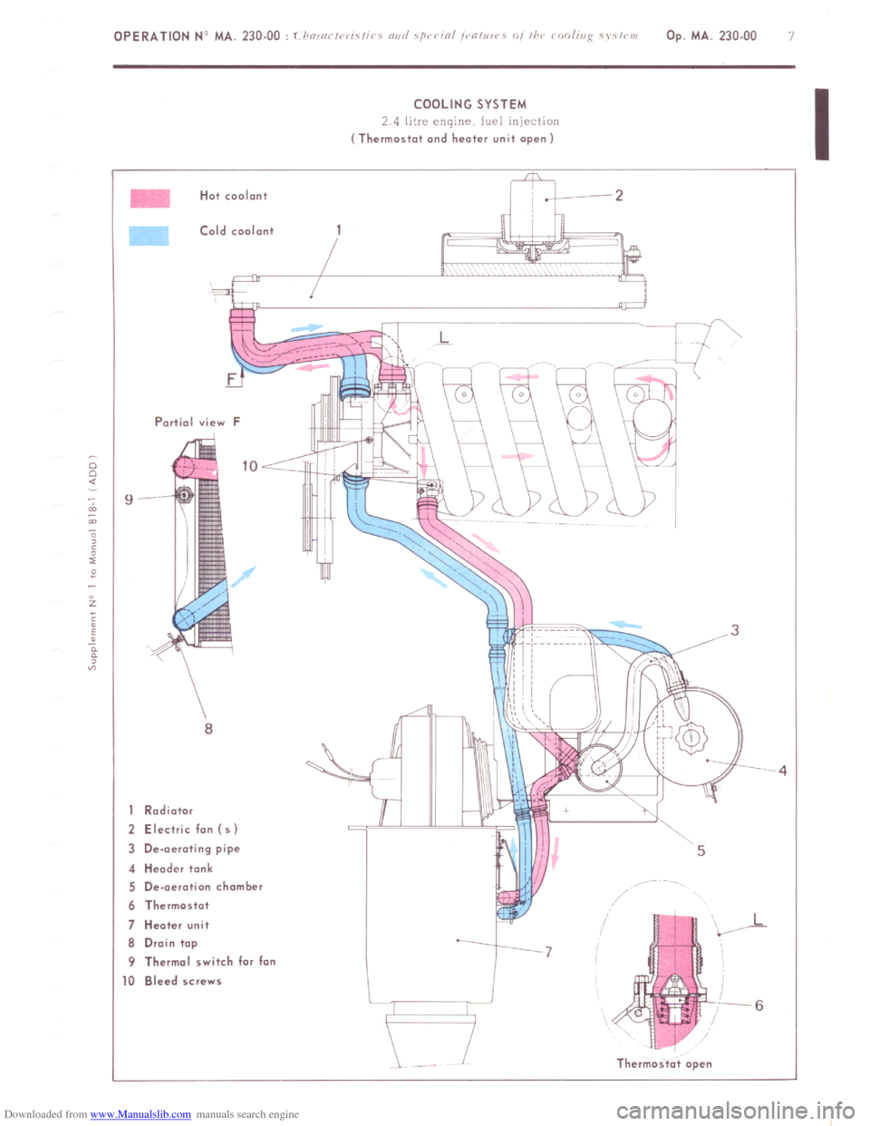
Downloaded from www.Manualslib.com manuals search engine OPERATION NJ MA. 230.00 : 1 i !O,Oi ,V,iC,i< c “ii<, ‘/QC < iOi ,< “,,i!< 0, ii’<
Op. MA. 230.00 7
COOLING SYSTEM
2 4 litre engine fuel injection (Thermostat and heater unit open)
Hat coolant
Cold coolant
Partial view F
1 Rodiotor
2 Electric fon (5)
3 De-aerating pipe
4 Header tank
5 De-aeration chamber
6 Thermostat
7 Heater unit
6 Drain top
9 Thermal switch for fan
0 Bleed screws
Thermast.t open