fuel filter Citroen CX 1982 1.G Workshop Manual
[x] Cancel search | Manufacturer: CITROEN, Model Year: 1982, Model line: CX, Model: Citroen CX 1982 1.GPages: 394
Page 4 of 394
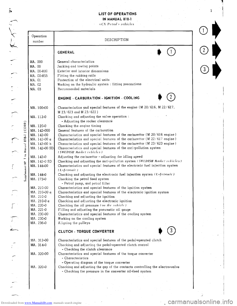
Downloaded from www.Manualslib.com manuals search engine Operation
number
VIA. 000
VIA. 00
VIA. 00-600
vlA. 00-655
VIA. 01
WA. 02
MA. 03
MA. 100-00
MA. 112-O
MA. 120-O
MA. 142-000
MA. 142-00
MA. 142-00 a
MA. 142-00 b
MA. 142-00 SI
MA. 142-O
MA. 142-O SD
MA. 144-00
MA. 144-O
MA. 173-O
MA. 210-00
MA. 210-00 a
MA. 210-O
MA. 210-O a
MA. 220-O
MA. 221-O
MA. 230-00
MA. 230-O
MA. 236-O
MA. 312-00
MA. 314-O
MA. 320-00
MA. 320-O LIST OF OPERATIONS
IN MANUAL 818-l
cc CX Petrol )) uehicles
DESCRIPTION GENERAL
General characteristics
Jacking and towing points
Exterior and interior dimensions
Fitting the rubbing rails
Protection of the electrical units
Working on the hydraulic system : fitting precautions
Recommended materials ENGINE - CA,RBURATlON - IGNITION - COOLING
+O 2
Characteristics and special features of the engine (M 20/616, M 22/ 617,
M 23/623 and M 23/622 )
Checking and adjusting the valve operation :
- Adjusting the rocker clearance
Checking the engine timing
General features of the carburation
Characteristics and special features of the carburettor (M 20/616 engine )
Characteristics and special features of the carburettor ( M 22/617 engine )
Characteristics and special features of the carburettor ( M 23/ 623 engine )
Characteristics and special features of the anti-pollution system
I SWEDISH Jlurket r,c~kicles )
Adjusting the carburettor - adjusting the idling speed
Checking and adjusting the anti-pollution system
(SIVI:‘DfSH Mdrkct rvhicles J
Characteristics and special features of the electronic fuel injection system
(L.~etKJnic )
Checking and adjusting the electronic fuel injection system (1..Jetrolzic)
Checking the petrol feed system
- Petrol pump, and petrol filter
Characteristics and special features of the ignition system
Characteristics and special features of the electronic ignition system
Checking and adjusting the ignition
Checkinq and adjusting the electronic ignition
Checking the oil pressure (on
the rvhicle )
Filling and adjusting the pneumatic oil gauge
Characteristics and special features of the cooling system
Working on the cooling system
Aligning the pulleys CLUTCH - TORQUE CONVERTER
*O 3
Characteristics and special features of the pedal-operated clutch
Checking and adjusting the pedal-operated clutch control
- Checking the clutch clearance
Characteristics and special features of the torque converter
- Characteristics
- Operating diagram of the torque converter
Checking and adjusting the gap of the contacts controlling the electro-valve
- Checking the pressure in the converter oil-feed system
Page 52 of 394
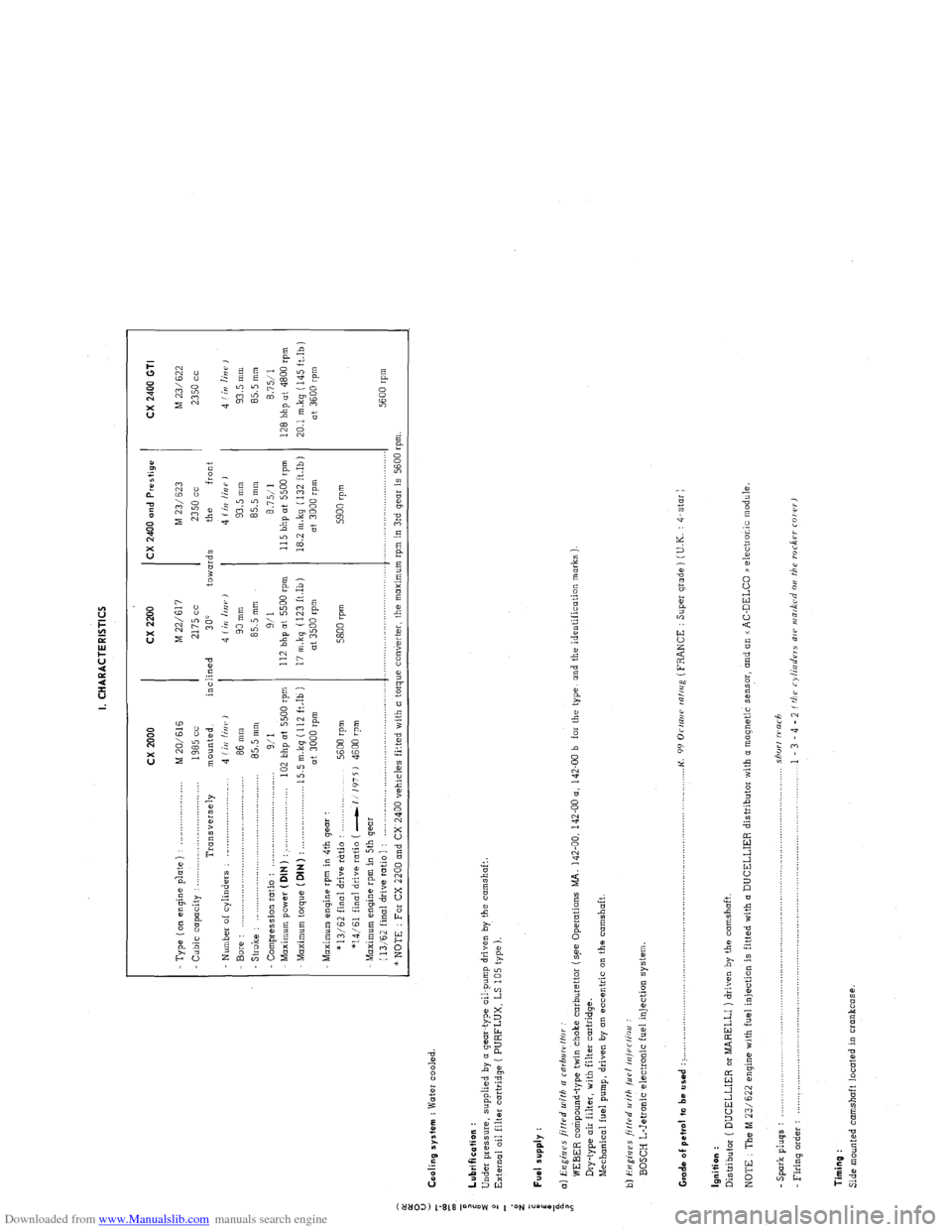
Downloaded from www.Manualslib.com manuals search engine I. CHARACTERISTICS
:
0
u
5 Cooling system : Water cooled.
z
T cx 2000 cx 2200 CX 2400 and Prestige
CX 2400 GTI
- Type ( on engine p’late ) : _..._................... M 20/616 M 22/617 M 23/ 623
M 23/622
Cubic capacity : . . .._......_...............
1985 cc 2175 cc 2350 cc 2350 cc
Transversely mounted, inclined
300 towards the front
Number of cylinders : _........................... 4 (iI/ linr, J 4 Iin linr,)
4 (irr /iUP J 4 f in lin i’ ,
Bore : 86 mm 90 mm 93.5 mm 93.5 mm
- Stroke : .,.,,_,.,.,....____.,.. .._._.....................
85.5 mm 85.5 mm 85.5 mm
85.5 mm
Compression ratio :
9/I 9/l 8.7511 8.7511
Maximum power ( DIN ) : . . . .._................... 102 bhp at 5500 rpm 112 bhp at 5500 rpm 115 bhp ot 5500 rpm
128 bhp at 4800 rpm
Maximum torque (DIN)
: . . 15.5 m.kg (112 ft.Ib ) 17 m.kq (123 ft.Ib) 18.2 m.kg ( 132 ft.Ib)
20.1 mkq (145 ft.Ib)
at 3000 rpm at 3500 rpm at 3000 rpm
at 3600 rpm
Maximum engine rpm in 4th gear :
* 13/62 final drive rtrtio :
5600 rpm 5800 rpm 5900 rpm
*14/61 final drive ratio ( -1 1’175 J 4600 rpm
Maximum engine rpm in 5th gear
(
13,‘62 final drive ratio ) : ,._............,..,........,....,.,........,..,.,..... .._.........,................ .._..._...................
5600 rpm
* NOTE : For CX 2200 and CX 2400 vehicles fitted with a torque converter, the maximum rpm in 3rd gear is 5600 rpm.
: Lubrification :
i
Under pressure, supplied by o gear-type oil-pump driven by the camshaft.
2
External oil filter cartridge ( PURFLUX, LS 105 type ).
d
z
;
i Fuel supply :
a
i a) Engines fitted u~ifh a rnrbuwffor
WEBER compound-type twin choke carburettor (s.ee Operations MA. 142-00, 142-00 a, 142-00 b far the type, and the identification marks )
Dry-type air filter, with filter cartridge.
Mechanical fuel pump, driven by on eccentric on the camshaft.
b) i?ugi,jes ji/f.rd II ith /LIP/ iniPr/ioo :
BOSCH L-Jetronic electronic fuel injection system
Grade of pet,ol to be used : > ._,,,,.,_.._,,,,,.,......... . .._...o....._............................................. K.
99 Orrani ralrrig (FRANCE : Super grade ) (U.K. : 4-star )
Ignition :
Distributor ( DUCELLIER or MARELLI ) driven by the camshaft.
NOTE : The M 23/622 engine with fuel injection is fitted with (I DUCELLIER distributor with a magnetic sensor, and an u AC-DELCO /a electronic module.
- Spark pluqs : .................................................................................................................................... shorf warh
Firing o&r : .................................................................................................................................... 1 - 3 - 4 - 2 f tbu cylinders ale INR&Cd 011 the roc6w COI rr,
Timing :
Side mounted camshaft located in crankcase.
Page 98 of 394
Downloaded from www.Manualslib.com manuals search engine 2
OPERATION No MA.IE. 144-00 : Chtiractcristics o/ the e 1,-Jc,tror,ic H clcctroltic
fire1 injc ctiwt systettt.
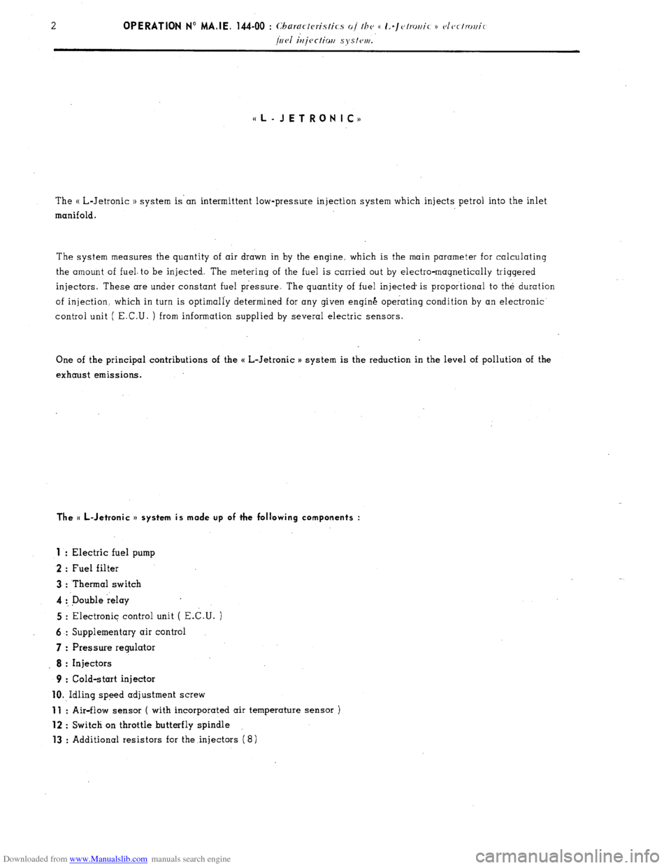
((L-JETRONIC,,
The H L-Jetronic 1) system is’an intermittent low-pressure injection system which injects petrol into the inlet
manifold.
The system measures the quantity of air drawn in by the engine. which is the main parameter for calculating
the amount of fuel. to be injected. The metering of the fuel is carried out by electro-magnetically triggered
injectors. These are under constant fuel pressure. The quantity of fuel injected is proportional to the duration
of injection. which in turn is optimally determined for any given engin& operating condition by an electronic
control unit ( E.C.U. ) from information supplied by several electric sensors.
One of the principal contributions of the H L-Jetronic H system is the reduction in the level of pollution of the
exhaust emissions.
The (( L-Jetronic v system is made up of the following components :
1
: Electric fuel pump
2 : Fuel filter
3 : Thermal switch
4 :, Double relay
5 : Electronic control unit ( E.C.U. )
6 : Supplementary air control
7 : Pressure regulator
8 : Injectors
9 : Cold-start injector
10. Idling speed adjustment screw
11 : Air-flow sensor ( with incorporated air temperature sensor )
12 : Switch on throttle butterfly spindle
13 : Additional resistors for the injectors (8)
Page 100 of 394
Downloaded from www.Manualslib.com manuals search engine OPERATION No MA.IE. 144-00 : Chu~acte~istics of the (( L-Jetronic n electronic
fuel injectiari system Op. MA.IE. 144-00 5
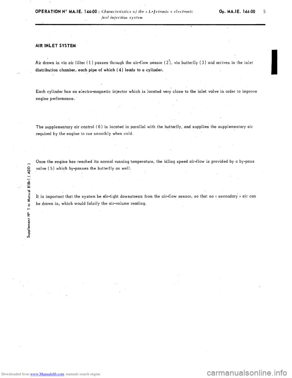
-AIR INLET SYSTEM’
Air drawn in via air filter ( 1 ) passes through the air-flow sensor (2’), via butterfly ( 3) and arrives in the inlet
distribution chamber, each pipe of which (4) leads to a cylinder.
-
‘I
Each cylinder has an electro-magnetic injector which is located very close to the inlet valve in order to improve
engine performance.
The supplementary air control (6) is located in parallel with the butterfly, and supplies the supplementary air
required by the engine to run smoothly when cold.
_ Once the engine has reached its normal running temperature, the idling speed air-flow is provided by a by-pass
valve
$ ( 5) which by-passes the butterfly as well.
.
2
co
T
$ It is important that the system be air-tight downstream from the air-flow sensor, so that no (( secondary )) air can
I
2 be drawn in, which would falsify the air-volume reading.
Page 101 of 394
Downloaded from www.Manualslib.com manuals search engine 6
OPERATION No MA.IE. 144 - 00 : Churacteristics o/ the H L-Jetronic )) electronic
/uel injectian .system. FUEL CIRCUIT
A multiple roller-valve pump ( 2 ) draws the fuel from tank ( 1) and provides the injection pressure,
A filter (4) is fitted to the system.
In the fuel return pipe, the pressure regulator ( 3) maintains, under fuel load! a relative constant fuel pressure of
2 bars ( 29 ‘psi ).
The pressure regulator is connected to the intake manifold by a flexible pipe0 This allows the difference of
pressure betw.een the fuel and the inlet manifold to remain constant.Thus the necessary quantity of fuel delivered
by the injectors ( 5) depends exclusively on its duration of opening.
Page 104 of 394
Downloaded from www.Manualslib.com manuals search engine OPEdATlON N- MA.IE. 144-00 : C1 3aractcJristics o/ the e L-Jetro~ic n elcctrorlir Op. MA.IE. 144-00 9
fuel injectian systwn. E.C.U; ( ELECTRONIC CONTROL UNIT )
Apart from three integrated circuits ( I.C. ) forming the main part of the E.C.U., there are in addition only a few
semi-conducting components condensers, calibrating resistors and filters so as to avoid.any interference.
I
The function of the E.C.U. is ,to supply an impulse to the injectors, and to control their opening for a precisely
defined amount of time. The E.C.U. to this effect uses the information provided by all the engine sensors which
translate the operating conditions of the engine into electric impulses.
All the injectors are connected in parallel, and inject fuel simultaneously twice for each rotation of the camshaft
( therefore,twice for each engine cycle ), injecting half the quantity of fuel required each time With this system
it is not necessary for the camshaft angle to coincide with the beginning of injection point, which eliminates the
need for a generating switch incorporated in the distributor.
The injection impulse control is ensured by the distributor impulses. The distributor produces four impulses for
every operational cycle. Since injection only occurs twice in every cycle, the E.C.U. must divide the frequency
by 2.
The impulses coming from the distriLti, are transformated into square waves by the waveform shaper. Since
injection only occurs twice for each camshaft rotation, whereas the distributor provides 4 impulses in the same
amount of time, the frequency of the impulses must be divided by 2 in the frequency divider.
These signals are used to charge a condenser. The condenser discharge determines the beginning of injection
point; the position of the air-flow sensor flap ( which determines the quantity of air drawn in ) being the main
parameter for calculating the duration of injection.
At the multiplying stage of the E.C.U., various correction values ( full load and idling speed via throttle butterfly
spindle switch, engine temperature via the water temperature sensor, air temperature via the air-temperature sensor
located in the air-flow sensor ) are combined with the signals from the air-flow sensor and the injt,ztion frequency
in order to determine the injection duration which is transmitted to the injectors by way of impulses.
The time it takes for the injector needle to open and close depends on the battery voltage.
As the supply voltage increases, the injection duration increases.
The fact that the quantity of fuel injected depends
on the voltage is cancelled out by the fact that the injection duration is inversely proportional to the voltaqq,in the
E.C.U.
The final impulse determines the time during which the injectors are connected to earth ( injection duration ‘supplied
by the output stage ).
Page 113 of 394
Downloaded from www.Manualslib.com manuals search engine ELECTRIC PETROL PUMP
The petrol pump is of the multi roller-vane type, driven by an electric motor which is energized as long as the
ignition is switched on. The rotor, which is fitted eccentrically in the pump housing, has metal roller vanes in
grooves around t.he periphery which, when they are forced outwards under the action of the centrifugal force, ensure
the system-is sealed.
Fuel is drawn into the cavities which,appear in between the roller-vanes, and is then forced into the injection
piping.
The electric motor is submerged’ in fuel. However, there .is no fire risk, since there is never any combustible
mixture in the pump housing. The pump supplies more fuel than the engine consumes under full load, so that
there is always sufficient pressure in the fuel system, whatever the engine speed. Excess fuel flows back to
the tank.
Once the ignition is on, the pump operates at the same time as the starter motor. Once the engine is running, the
airflow sensor energizes the pump.
Thanks to this type of.system, if an injector is faulty ( leaks ) the cylinder in question cannot be flooded if one
has ommitted to switch the ignition off. PETROL FILTER (1) :
A fuel filter, fitted between the pump and the injectors, prevents any impurities from reaching the injectors. PETROL PRESSURE REGULATOR ( 2 ) :
The fuel pressure is maintained constant by the pressure regulator. It comprises a metal housing
is a diaphragm., One side of the dipphragm.is subjected to the fuel under pressure, and the other 2
to the action of a calibrated spring. inside which
side is subjected
When the fuel pressure is in excess of 2 bars ( 29 psi ), the diaphragm lifts and allows fuel to flow back to the
tank.
The pressure provided by the regulator is pre-adjusted at the factory. The chamber on the side of the spring is
connected via a flexible pipe to the inlet manifold. Therefore, the difference between the pressure in the inlet
manifold and that of the fuel is maintained constant.
For any engine load, the drop in pressure at the injectors is therefore the same.
Page 149 of 394
Downloaded from www.Manualslib.com manuals search engine 28 OPERATION N” MA.IE. 144-O : Ch <,c ,ng n,,d nlfjusfiup Ihe u I.-~<~tro,,ir i) <~lrr/mr,ir k’
/,,,.I i,,jrr/io,, S~S,W1, ANNEXE : D - ADJUSTING THE IDLING SPEED AND THE EXHAUST EMISSION
CHECKING CONDITIONS
1.
Checking the idling speed must be carried out
on a clean engine on which the ignition and the
valve clearances are properly adjusted and
fitted with a clean air-filter.
2. Check that the throttle butterfly returns correctly
to its stop.
3. Do not load the alternator by switching an any
of the electrical components, except the iqnition
and the electric cooling fan (s) 4.
Run the engine to bring the oil temperature up
to 70 +o 80’ C ( wait for the electric cooling
fan is) to cut in ). IMPORTANT : Use exclusively (I high tension
tachometer ( do not damage the H.T. lead of
the ignition wiring harness ).
ADJUSTMENT
1. Check that the butterfly is not jammed in position
when it is resting against its stop.
2. Wait for the electric cooling fan (s) to cut in.
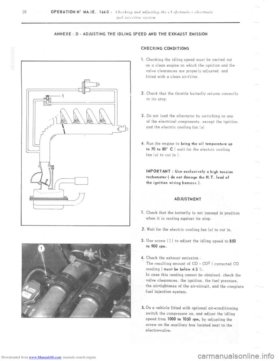
3. Use screw ( 1 ) to adjust the idling speed to 850
to 900 rpm.
4. Check the exhaust emission :
The resulting amount of CO - CO2 ( corrected CO
reading 1 must be beI& 4.5 %.
In case this reading cannot be obtained, check the
valve clearances, the ignition, the fuel pressure,
the air-tightness of the aircircuit, and the complete
fuel injection system.
5. On (I vehicle fitted with optional oirtonditioning
switch the compressor on, and adjust the idling
speed from 1000 to 1050
rpm, by adjusting the
screw on the auxiliary box located next to the
electro-vol”e.