steering wheel Citroen CX 1982 1.G Workshop Manual
[x] Cancel search | Manufacturer: CITROEN, Model Year: 1982, Model line: CX, Model: Citroen CX 1982 1.GPages: 394
Page 5 of 394
Downloaded from www.Manualslib.com manuals search engine .r.
-/1
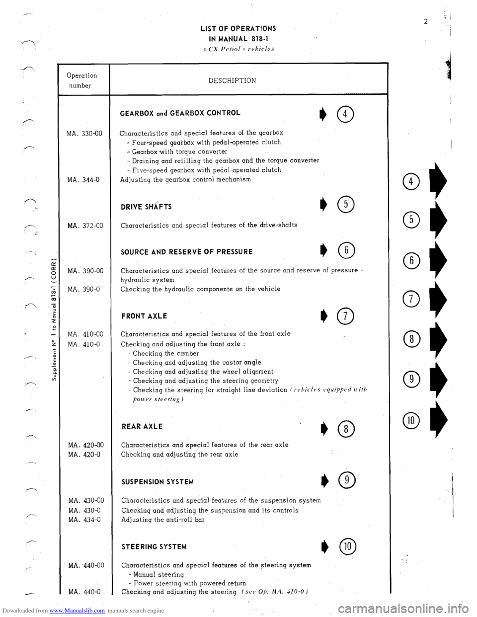
LIST OF OPERATIONS
IN MANUAL 818-1
a CX Petrol )) 7,rhifles
--
-
f-7
i---- _--
-
Operation
number
MA. 330-00
MA . . 344-O
MA. 372-00
MA. 390-00
MA. 390-O
MA. 410-00
MA. 410-O
MA. 420-00
MA. 420-O
MA. 430-00
MA. 430-O
MA. 434-O
MA. ,440-00
MA. 440-O DESCRIPTION GEARBOX and GEARBOX CQNTROL
*O 4
Characteristics and special features of the gearbox
- Four-speed gearbox with pedal-operated clutch
- Gearbox.with torque converter
- Draining and refilling the gearbox and the torque converter
- Five-speed gearbox with pedal-operated clutch
Adjusting the gearbox control mechanism DRIVE SttiFTS
Characteristics and special features of the drive-shafts SOURCE AND RESERVE OF PRESSURE
Characteristics and special features of the source and reserve of pressure -
hydraulic system
Checking the hydraulic components on the vehicle FRONT AXLE
+O 7
Characteristics and special features of the front axle
Checking and adjusting the front axle :
- Checking the camber
- Checking and adjusting the castor angle
- Checking and adjusting the wheel alignment
- Checking and adjusting the steering geometry
- Checking the steering for straight line deviation (
whirfes cjq77ippcJrl with REAR AXLE
*O 8
Characteristics and special features of the rear axle
Checking and adjusting the rear axle SUSPENSION SYSTEM
I,0 9
Characteristics and special features of the suspension system
Checking and adjusting the suspension and its controls
Adjusting the anti-roll bar STEERING SYSTEM
*@
Characteristics and special features of the steering system
- Manual steering
- Power steering with powered return
Checking and adjusting the steering (see Op. MA. 410-O )
Ob
4
Ob 5
Ok 6
Ok 7
O+ 8
O1) 9
Page 9 of 394
Downloaded from www.Manualslib.com manuals search engine OPERATION N” MA. 000 : G~~/c~rnl chnracteris/ics Op. MA. 000 3
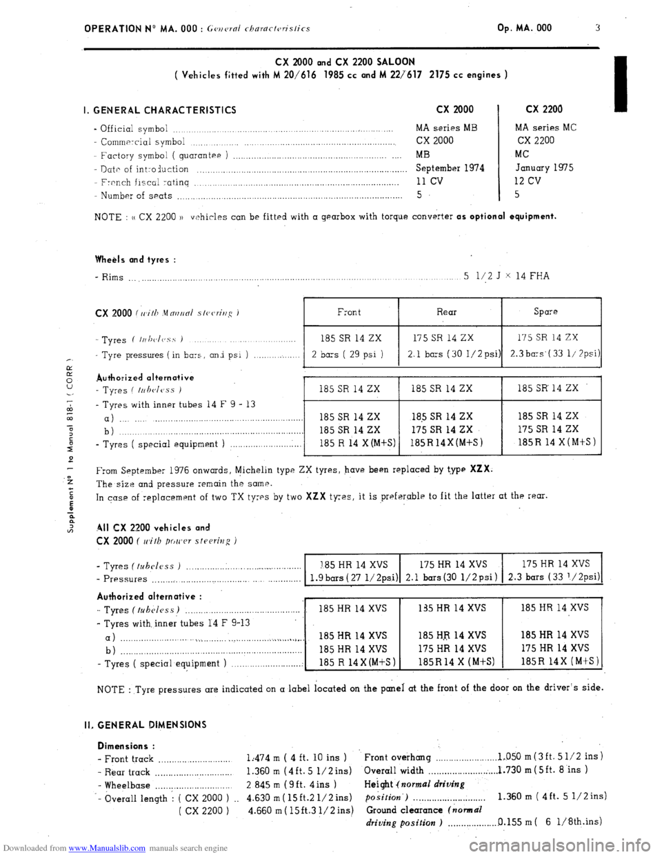
CX 2000 and CX 2200 SALOON
( Vehicles fitted with M 20/616 1985 cc and M 227617 2175 cc engines )
I. GENERAL CHARACTERISTICS
cx 2000 cx 2200 I
- Official symbol .._... _. .._................. .._. MA series MB MA series MC
- Commercial symbol ., ,. . .._._.._............._........................ cx 2000 cx 2200
Factory symbol
( quarantee ) _._,_..,,.__._..__._..................,.................... . . . . MB MC
- Date of int:oduction . . ..__..._.._....._._..............,.......................,,........,.,...... September 1974 January 1975
- French fiscal ratinq ,.....,...._..._...._,......................,,..,..,........................... 11 cv 12 cv
- Number of seats ._...._...__._..................................,....,...,....................,........ 5 5
NOTE : u CX 2200 1) vi?hicles can be fitted with a gearbox with torque converter
as optional equipment.
Wheels and tyres :
_ Rims ___,._.__.__.__.,.._..._..,. ..,.,,.___..._._.....__.....................,...,...................... .,. _ ..__......_..._ 5 l/2 J X 14 FHA
CX 2000 (rrlith .\fmun/ s/eerir/g 1
- Tyres ( /II/~c~/(~s.s )
Tyre pressures ( in bars, and psi ) ._..__..._._. 2 bars ( 29 psi ) ;I
2.1 bars (30 1/2psi) 2.3 ba:s‘( 33 I/ 7psi)
Authoaized alternative ,
- Tyres ( ~r~l~c~less )
185 SR 14 ZX 185 SR 14 ZX 185 SR 14 ZX
- Tyres with inner tubes 14 F 9 - 13
a) _.., _._. .._,,....___,.__._......................................... 185 SR 14 ZX 18.5 SR 14 ZX 185 SR 14 ZX
b ) . 185 SR 14 ZX 175 SR 14 ZX 175 SR 14 ZX
-
Tyres ( special equipment ) _...._._,,.....__._......... 185 R 14 X(M+S) 185R14X(M+S) 185R 14 X(MtS)
From September 1976 onwards, Michelin type ZX tyres, have been replaced by t.ype
XZX.
The size and pressure remain the same.
In case of replacement of two TX tyres by two
XZX tyres, it is preferable to fit the latter at the rear.
All CX 2200 vehicles and
CX 2000 ( with power steering )
- Tyres (tubeless ) . . ..__._._._.___... ..___.__.._......._.._._ I85 HR 14 XVS 175 HR 14 XVS 175 HR 14 XVS
- Pressures __.,._.__.,__...._.,....~.......,...... ._ .___......... l.gbars(27 1/2psi) 2.1 bars(30 1/2psi) 2.3 bars (33 ‘/2psi)
Authorized alternative :
-1 Tyres (tubeless) _._....._..,___._._....,.,...........,..,.... 185 HR 14 XVS
- Tyres with, inner tubes 14 F 9-13
a) . . . . . . . . . . . . . . . . ..i,..,..___._. .,.._.._.~_..__~.~..~ j.,_~.~._.
b) _____.__,,..,..__.__...................................................
- Tyres ( special equipment ) __...._,.___...............; , .~~~,
NOTE : Tyre pressures are indicated on a label located on the panel at the front of the door on the driver’s side.
II. GENERAL DIMENSIONS
Dimensions :
- Front track ..,..,_.__.................. 1:474 m ( 4 ft. 10 ins ) Front overhang . . . . . . . . . . . . . . . .._...... 1~050 m(3ft. 5 l/2 ins)
- Rear track . . . . . . . . . . . .._._.............. 1.360 m (4ft. 5 l/2 ins)
Overall width . . . . . . . . . . . . . . . . . . . . . . . . . . . 1.730 m ( 5ft. 8 ins )
- Wheelbase . . . . . . . . . . . . ..____............ 2 845 m (9ft. 4ins ) Height {normal
driving
-- bverall length 1 ( CX 2000 ) __ 4.630 m( 15ft.2 1/2ins) position’) . . . . . . . . . . . . . . . . . . . . . . . . . . . . 1.360 m ( 4ft. 5 1/2ins)
( cx 2200 ) 4.660 m ( 15ft.3 l/2 ins) Ground clearance (normal
driving position ) . . . . . . . . . . . . . . . . . . . 0.155 m ( 6 1/8th.ins)
Page 11 of 394
Downloaded from www.Manualslib.com manuals search engine OPERATION No MA. 000 : General characteristics Op. MA. 000
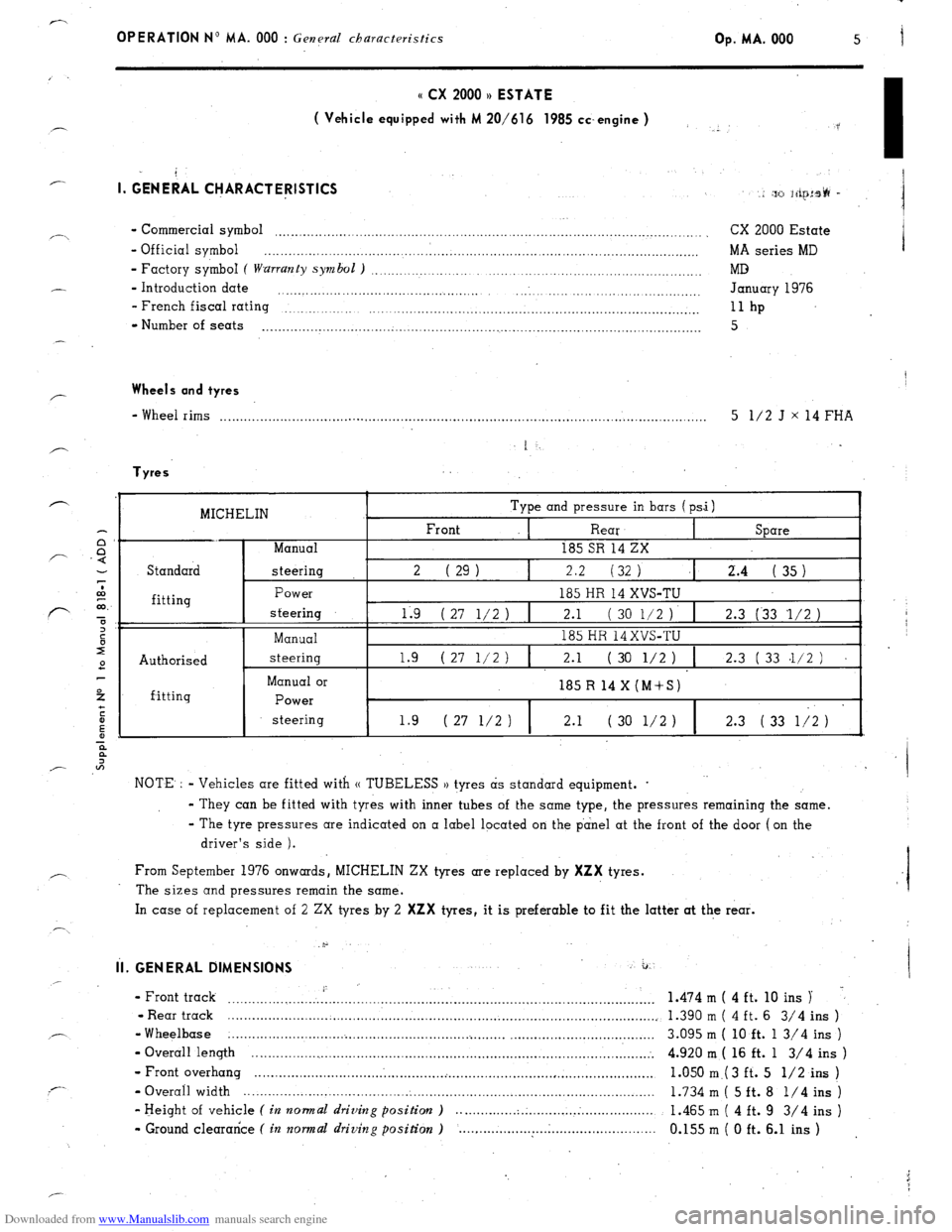
o CX 2000 u ESTATE
( Vehicle equipped with M 20/616 1985 cc.engine )
I. GE&AL Cl-jARACTERlSTlCS I.
:p> ;firJ:s@ -
. . - Commercial symbol . . . . . . . . . . . . . . . . . . . . . . . . . . . . . . . . . . . . . . . . . . . . . . . . . . . . . . . . . . . . . . . . . . . . . ..~.................................. I
CX 2000 Estate
- Official symbol . .._._.._._............................................................... . . . . . . . . . . . . . . . . . . . . . ..__......... MA series MD
- Factory symboI ( warranty symbol ) . . . . . . . . . . . . . _..__......................_...._..,.,......, MD
- Introduction date _... . . . . . . .,.,.,.,,..............,.,.,.... January 1976
- French fiscal rating
. . . . . . . . . . . ..~........................................................................... llhp
- Number of seats . . . . . . . . . . . . . . . . . . . . . . . . . . . . . . . . . . . . . . . . . . . . . . . . . . . . . . . . . . . . . . . . . . . . . . . . . . . . . . . . . . . . . . . . . . . . . . . . . . . . . . . . . . . . . 5
Wheels and tyres
- Wheel rims . . . . . . .._............................................................................................................... 5 l/2 J x 14 FHA
Tyres
MICHELIN Type and pressure in bars (psi)
Front
I Rear Spare
Manual 185 SR 14 ZX
Standard steering 2 ( 29 1 2.2 (32 1
2.4 35 I .I ( )
fitting
Authorised
f-itting Power
steering
Manual
steering
Manual or
Power
steering 185 HR 14 XVS-TU
119 ( 27 l/2 ) ,I 2.1 ( 30 l/2 ). 1 2.3 (33 ‘l/2 )
185 HR 14XVS-TU
1 I
1.9 (27 l/2) 2.1 ( 30 l/2 ) 2.3 ( 33 .1/2 )
185 R 14 X (M+S)
1.9 ( 27 l/2 ) 2.1 ( 30 l/2 1
2.3 ( 33 1;2 )
NOTE. : - Vehicles are fitted with (( TUBELESS )) tyres as standard equipment. .
- They can be fitted with tyres with inner tubes of the same type, the pressures remaining the same.
- The tyre pressures are indicated on a label located on the panel at the front of the door (on the
driver’s side ).
From September 1976 onwards, MICHELIN ZX tyres are replaced by
XZX tyres.
The sizes and pressures remain the same.
In case of replacement of 2 ZX tyres by 2
XZX tyres, it is preferable to fit the latter at the rear.
.p
il. GENERAL DIMENSIONS a.
I ~.
- Front track
..........................................................................................................
- Rear track ........................ .:.
................................................................................
-Wheelbase .......................................................... ..i ........ ....................................
- Overall length .....................................................................................................
- Front overhang
............................................. ..i ...................................................
- Overail width ......................................................................................................
- Height of vehicle ( in normal driving position ) ............... . .................................
- Ground clearance ( in normal driving position ) ................................................. 1.474 m ( 4 ft. 10 ins )
1.390 m ( 4 ft. 6 3/4 ins )
3.095 m ( 10 ft. 1 3/4 ins )
4.920 m ( 16 ft. 1 3/4 ins )
1.050 m.( 3 ft. 5 l/2 ins )
1.734 m ( 5 ft. 8 l/4 ins )
1.465 m ( 4 ft. 9 3/4 ins )
0.155 m ( 0 ft. 6.1 ins )
Page 13 of 394
Downloaded from www.Manualslib.com manuals search engine OPERATION No MA. 000 : General characteristics Op. MA. 000 7
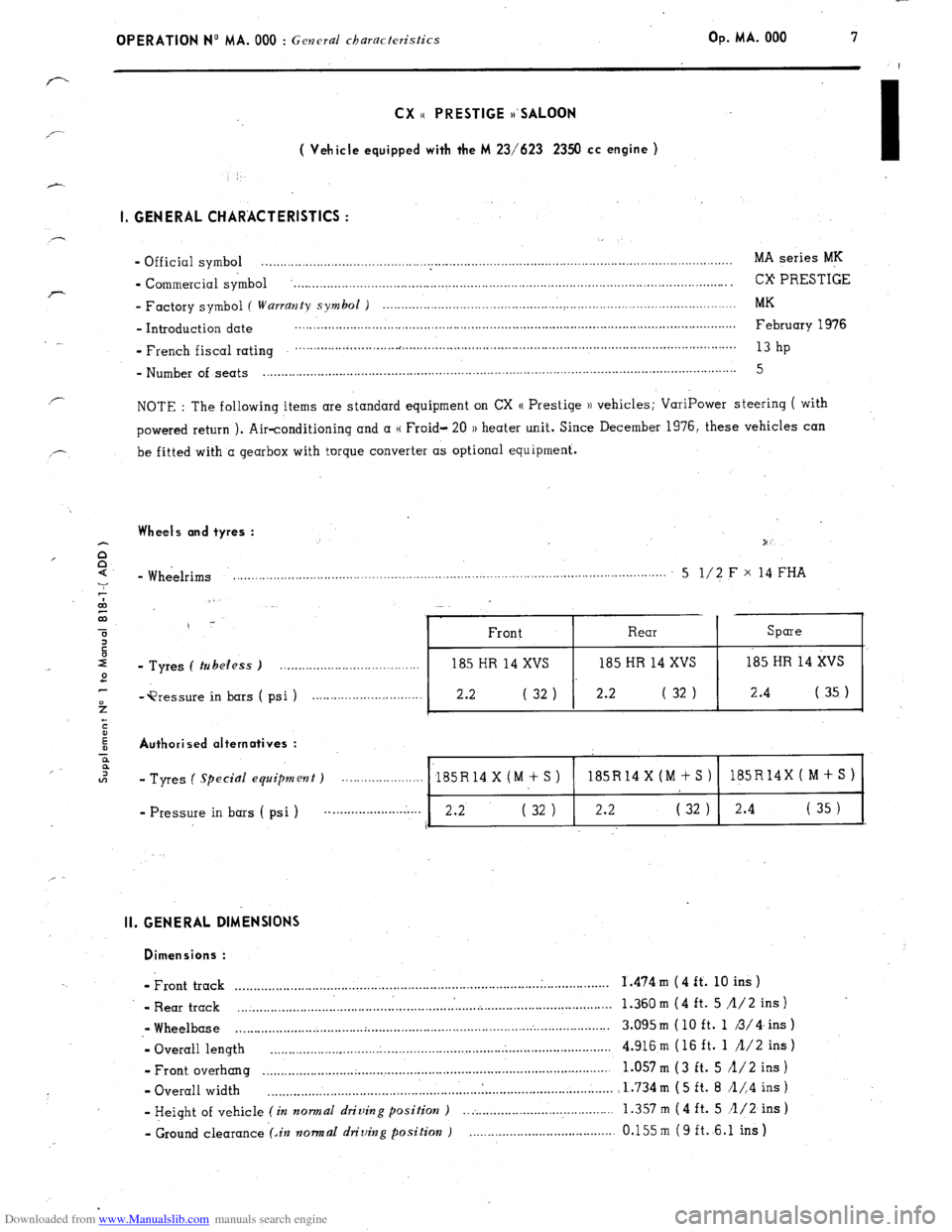
CX ,, PRESTIGE ,,‘SALOON
: ( Vehicle equipped with the M 23/623 2350 cc engine )
1. GENERAL CHARACTERISTICS :
- Official symbol MA series MK ................................................................................................................................
- Commercial symbol ........................................................................................................................ CX PRESTIGE
- Factory symbol ( Wurrmzty symbol ) .................................................
:. .............................................
MK
- Introduction date ........................................................................................................................
February 1976
_ French fiscal rating
............................. , ........................................................................................... 13
hp
- Number of seats . . . . . . . . . . . . . . . . . . . . . . . . . . . . . . . . . . . . . . . . . . . . . . . . . . . . . . . . . . 5
NOTE : The following items are standard equipment on CX (( Prestige )) vehicles; VariPower steering ( with
powered return ). Air-conditioning and a (( Froid- 20 1) heater unit. Since December 1976, these vehicles can
be fitted with’a gearbox with torque converter as optional equipment.
Wheels and tyres :
- Wheelrims .,...,._.__._......_...,.................,,....,................................................. . . . . . . . . . . . . . . . 5 l/2 F x 14 FHA
- Tyres ( tubeless ) . . . . . .
(psi) . . . . . . . . . . . . .._.._.......... )
2.2
Authorised alternatives :
-‘Pressure in bars
- Tyres ( .Ppecial equipment) . . . . . . .
185R14 X (M + S ) 185R14X(M+S) 185R14X(M+S)
- Pressure in bars ( psi ) . . . . . . . . . . . . . . . . . . . . 2.2’ ( 32 ) 2.2 ( 32 ) 2.4
( 35 )
I
II. GENERAL DIMENSIONS
Dimensions :
- Front track ......................................................................................................
1.474m (4ft. loins)
- Rear track
... . ................................................................................................... 1.360 m (4 ft. 5 /l/2 ins )
,- Wheelbase ................................... . ...................................................................
3.095m (10 ft. 1 3/4.ins)
- Overall length ............................................................................................. 4.916 m ( 16 ft. 1 /l/2 ins )
- Front overhang ...............................................................................................
1.057 m (3 ft. 5 A/2 ins )
- Overall width ............................................................................................... 1.734m (5 ft. 8 /l/,4 ins)
- Height of vehicle (in normal driving position ) .. :. ..................................... 1.357
m ( 4 ft. 5 /l/2 ins )
- Ground clearance (An normal driving position ) ........................................ 0.155m (9 ft. 6.1 ins)
Page 17 of 394
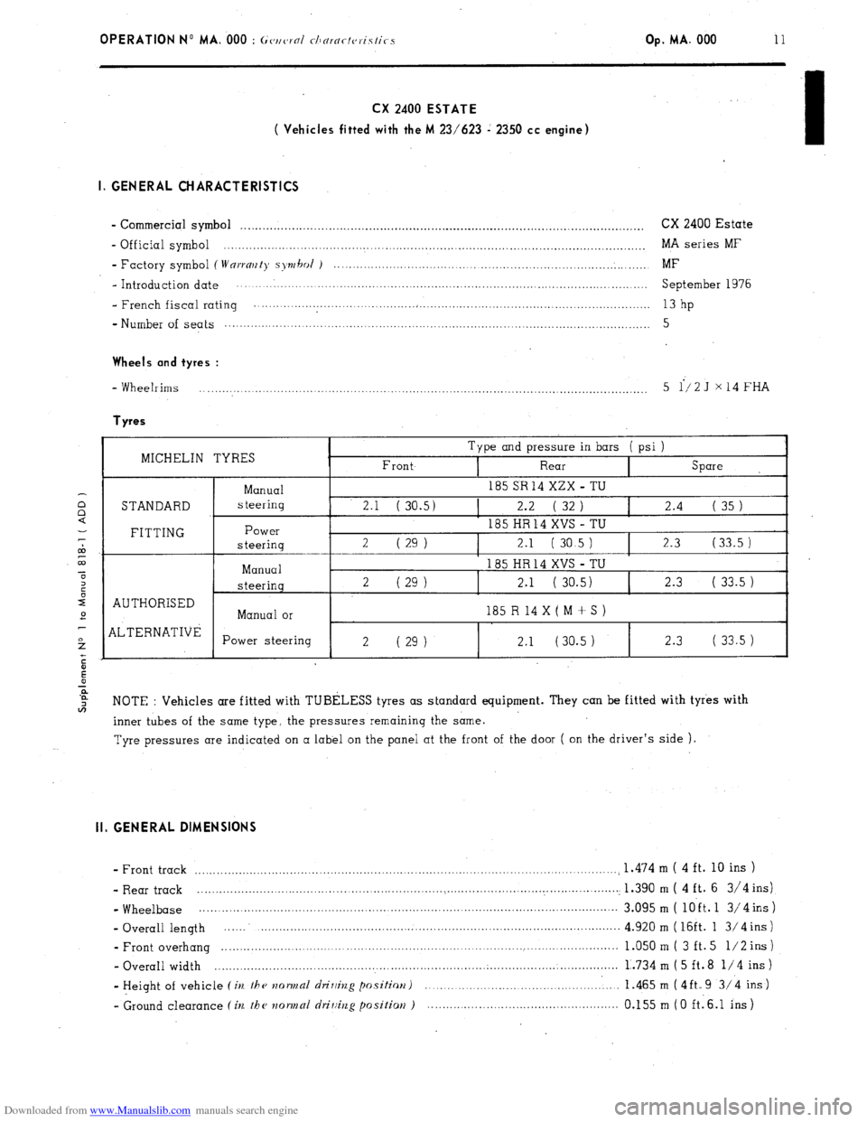
Downloaded from www.Manualslib.com manuals search engine OPERATION No MA. 000 : ~(~tlc,rol tllNrar/vristics Op. MA. 000 11 CX 2400 ESTATE
( Vehicles fitted with the M 23/623 i 2350 cc engine)
I, GENERAL CHARACTERISTICS
- Commercial symbol _. ............................................................................................................ CX 2400 Estate
- Official symbol ................................................................................................................... MA series MF
- Factory symbol (
Wnrrmty syrh~l i ...................................................................................... MF
- Introduction date ................................................................................................................ September 1976
- French fiscal rating ............................................................................................................
13 hp
- Number of seats ................................................................................................................... 5
Wheels
and tyres :
- Wheelrims
.......................................................................................................................... 5 i/2J x14FHA Tyres
MICHELIN TYRES Type and pressure in bars ( psi )
I _-- --.
--ZX - TU
STANDARD
I AUTHORISED
] ALTERNATIVE Manual
steering
Power
steering
-_
Manual
steering
Manual or
Power steering 185 SH 14 xi
2.1 ( 30.5) 2.2 ( 32 ) I 2.4 ( 35 )
185 HR 14 XVS TU -
2 ( 29 1 2.1 ( 30.5 ) 2,3 (33.5 )
185 HR14 XVS TU -
2 ( 29 1 2.1 ( 30.5) 2.3 ( 33.5 )
185 R 14 X ( M + S )
2 ( 29 ) 2.1 (30.5 1 2.3 ( 33.5 )
NOTE : Vehicles are fitted with TUBELESS tyres as standard equipment. They can be fitted with tyres with
inner tubes of the same type, the pressures remaining the same.
Tyre pressures are indicated on a label on the panel at the front of the door ( on the driver’s side ). II. GENERAL DIMENSIONS
- Front track ....................................................................................................................
1.474 m ( 4 ft. 10 ins )
- Rear track ................................................................... _ ................................................ . 1.390 m ( 4 ft. 6 314 ins)
- Wheelbase .................................................................................................................. 3.095 m ( loft. 1 3/4 ins )
- Overall length .........................................................................................................
4.920 m ( 16ft. 1 3/ 4 ins )
- Front overhang ........................................................................................................... 1.050 m ( 3 ft. 5 l/2 ins )
- Overall width .............................................................................................................. 1..73 4 m ( 5 ft. 8 l/4 ins )
- Height of vehicle (ie the ~zormal drilhzg positim) ..................................................... 1.465 m (4ft.9 3/4 ins)
- Ground clearance (in the ?zormal driuiug positiaN ) .................................................... 0.155 m (0 ftl6.1 ins)
Page 21 of 394
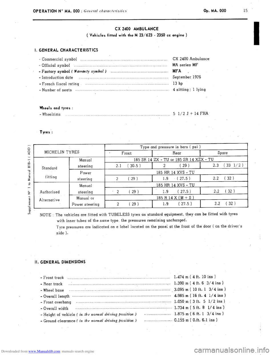
Downloaded from www.Manualslib.com manuals search engine OPERATION No MA. 000 : Gwcrnl churactcristics Op. MA. 000 15 CX 2400 AMBULANCE
( Vehicles fitted with the M 23/623 - 2350 cc engine )
I, GENERAL CHARACTERISTICS
- Commercial symbol ........................................................................... CX 2400 Ambulance
- Official symbol ................................................................................ MA series MF
- Factory symbol ( Warranty symbol. ) .................................................
MFA .
- Introduction date .............................................................................. September 1976
- French fiscal rating ........................................................................
13 hp
_ Number of seats .................................................................................. 4 sitting ; 1 lying Wheels and tyres :
- Wheelrims ,._..._._..,_.. ,,...,_..__._._._.._.................,...,,.,,..,.,,...,....,..,..,....... 5 l/2 J f 14 FHA Tyres-:
:: Type and pressure in bars ( psi )
=l MICHELIN TYRES
Front
I Rear
I Spare
CA Manual 185 SR 14 ZX - TU or 185 SR 14 XZX - TU
co Standard steering 2.1 ( 30.5 ) I 2 ( 29 1 I 2.3 (33
l/2)’
a
z Power 185 HR 14 XVS TU -
r” fitting steering 2 ( 29 1 I 1.9 ( 27.5 ) I 2.2 ( 32 )
e
Manual 185 HR 14 XVS - TU
t Authorised steering 2 (29) 1. 1.9 ( 27.5 ) I 2.2 ( 32
)
+
5
Alternative Manual or 185 R 14 X (M t S )
E
1 steering I Power 2 29 1.9 ( 27.5 ) 2.2 ( 32
( 1 )
a
a
2
NOTE : The vehicles are fitted with TUBELESS tyres as standard equipment, they can be fitted with tyres
with inner tubes of the same type, the pressures remaining unchanged.
Tyre pressures are indicated on a label located on the panel at the front of the door ( on the driver’s
side ). II. GENERAL DIMENSIONS
- Front track ........................................................................................ 1;474 m ( 4 ft. 10 ins )
- Rear track _.I..
...................................................... . ......................... i .. 1.390 m ( 4 ft. 6 3/4 ins )
- Wheel base .......................................................................................
.3.095m( loft. 1 3/4ins)
_ Overall length .......................................................................... ..~ ........
4.985 m ( 16 ff. 4 l/4 ins )
- Front overhang ..................................................................................
1.050 m ( 3 ft. 5 l/2 ins )
- Overall width ...................................................................................
1.734 m ( 5 ft. 8 l/4 ins ‘)
- Height of vehicle
( in .the nornz~l driuing position ) ....................... 1.875 m,( 6 ft. 1 3/4 ins )
- Ground clearance
( in the normal driuing positian ) ........................ ,a.155 m ( O.ft. 6.1 ins )
I
Page 241 of 394
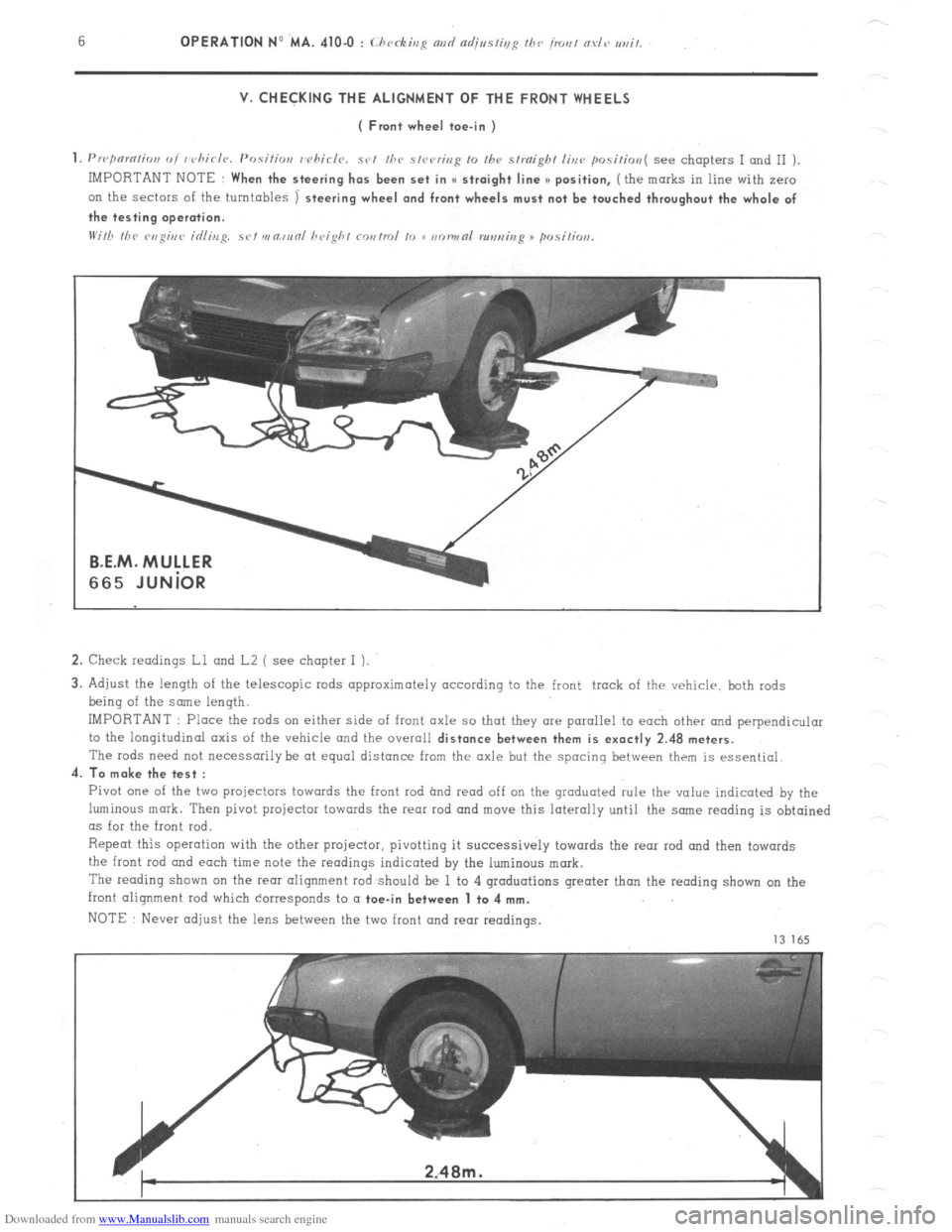
Downloaded from www.Manualslib.com manuals search engine V. CHECKING THE ALIGNMENT OF THE FRONT WHEELS
( Front wheel toe-in )
1. Prrpnmtion oi whirlr~. Positior,
whirls. set /he s,rering 10 Ihv straight line positim~( see chapters I and II )
IMPORTANT NOTE
When the steering has been set in I( straight line >) position, (the marks in line with zero
on the sectors of the turntables
1 steering wheel and front wheels must not be touched throughout the whole of
the testing operation.
2. Check readings Ll and L2 ( see chapter I ).
3. Adjust the length of the telescopic rods approximately according to the front track of the vehicle, both rods
being of the some length.
IMPORTANT : Place the rods on either side of front axle so that they are parallel to each other and perpendicular
to the longitudinal axis of the vehicle and the overall
distance between them is exactly 2.48 meters.
The rods need not necessarily be at equal distance from the axle but the spacing between them is essential.
4.
To make the test :
Pivot one of the two projectors towards the front rod hnd read off on the graduated rule thr value indicated by the
luminous mark. Then pivot projector towards the rear rod and move this laterally until the snne reading is obtained
as for the front rod.
Repeat this operation with the other projector, pivotting it successively towards the rear rod and then towards
the front
rod and each time note the readings indicated by the luminous mark.
The reading shown on the rem alignment rod should be 1 to 4 graduations greater than the reading shown on the
front alignment rod which corresponds to a
toe-in between 1 to 4 mm.
NOTE Never adjust the lens between the two front and rear readings.
13 165
Page 243 of 394
Downloaded from www.Manualslib.com manuals search engine a OPERATION N’ MA. 410-O : (./~rrkiq N,,I/
VI. CHECKING AND ADJUSTING THE STEERING GEOMETRY
The crossmember supporting the steering has slots at its fixing point on the front subframe.
Any vertical movement of this crossmember alters the steering geometry.
WARNING
This operation is only to
be carried out in certain ccxses such as
-accidental impact, with repercussions on the steering system.
-work on the vehicle entoiling removal of steering crossmember.
- vehicle with poor
road stability ( p oar stright-line stability) 01 with excessive tyre weor.
CHECKING
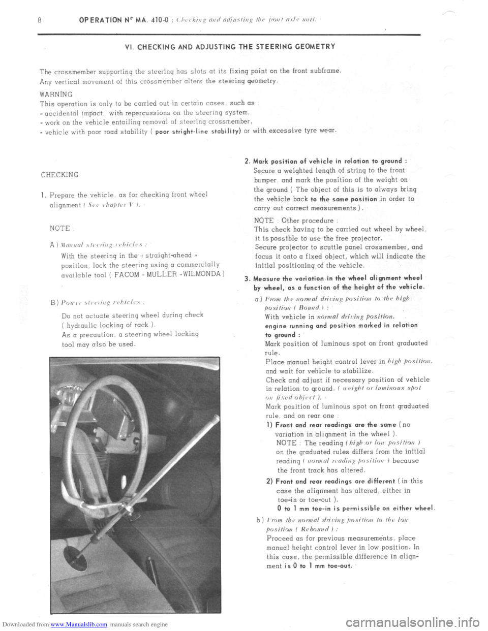
1, Prepare the vehicle. as for checking front wheel
alignment ( Srr ~ho/,lvr
V I.
NOTE
A ) \In,,unl ~fi~<,r;,,~ I chiclvs :
With the steering in the /< straightahead 1)
position. lock the steering using CI commercially
available tool ( FACOM _ MULLER -WILMONDA)
B) PO,, P)’ \,r,rr;ng r’cliirl<,.s :
Do not actuate steering wheel during check
( hydraulic locking of rock 1.
As a precaution. a steering wheel iocking
tool may also be
used. 2. Mark position of vehicle in relation to
ground :
Secure a weighted length of string to the front
bumper. and
mark the position of the weiqht on
the ground ( The
object of this is to always bring
the vehicle
bock to the some position in order to
carry out correct measurements 1.
NOTE Other procedure
This check having to be carried out wheel hy wheel.
it is possible to use the free projector.
Secure projector to scuttle panel crossmemher, and
focus it onto a fixed object, which will indicate the
initial positioning of the vehicle.
3. Measure the variation in the wheel alignment wheel
by wheel, ds o function of the height of the vehicle.
a) From Ihc m~nwnl rlri,:ir,g posi/ior, lo /hc hi@
posilio,, f ftouad 1 :
With vehicle in mwmal rlriving position.
engine running ond position marked in relation
to groond :
Mark position of luminous spot on front graduated
rule.
Place m’anual height control lever in hi&
posilirrrl.
and wait for vehicle to stabilize.
Check and adjust if necessary position of vehicle
in relation to ground. ( II
eight 01 Inmbrous spol
ou /i wd 0 hit,< I J.
Mark position of luminous spot on front graduated
rule. and on rear one
1) Front and rear readings ore the some (no
variation in alignment in the wheel 1.
NOTE : The reading f I,i$ or lorr posilios J
on the qroduated rules differs from the initial
reading f non,,nl >r,nrlinl:
position J because
the front track has altered.
2) Front and rear readings ore different ( in this
case the alignment has oltered,.either in
toe-in or toe-out ).
0 to 1 mm toe-in is permissible on either wheel
b) ,:rr ,,I, /bv IIDIINRI hi&g ,,osi,;orr lo ,I,<, lo,,
posiliov f Hrlmuad ) :
Proceed OS for previous measurements, place
manual height control lever in low position. In
this case. the permissible difference in oliqn-
ment
is O.to 1 mm toe-out.
Page 244 of 394
Downloaded from www.Manualslib.com manuals search engine OPERATION No MA. 4104 : (./ , k’ 1
ADJUSTMENT
NOTE The steering crossmember will have to be
moved (IS a function of the readings obtained during
checkinq
01) Towards the top to
obtain
_ toe-out ir, Ihe hish positim
- toe-in irr the 10~ psitios
b) Towards the bottom
to obtain
.
toe-in in Ihr hi& posilins
- toe-out iu fhc IOU posilios
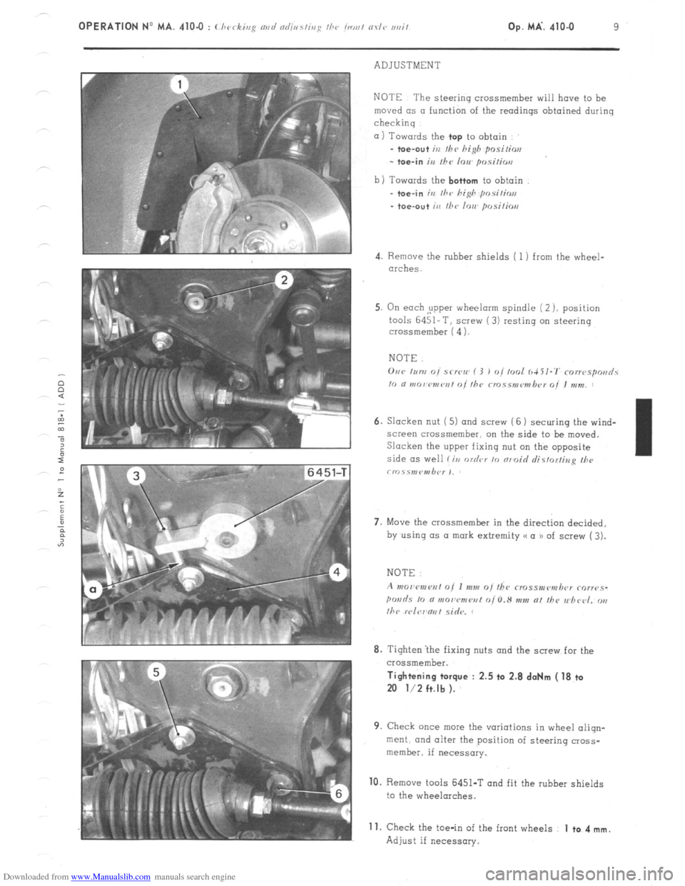
4. Remove the rubber shields ( 1 ) from the wheel-
arches.
5. On each ,upper wheelorm spindle (2 ). position
tools 6451-T, screw (3) resting on steering
crossmember ( 4 1.
NOTE.
6. Slacken nut ( 5) and screw (6 1 securing the wind-
screen crossmember. on the side to be moved.
Slacken the upper fixing nut on the opposite
side as well li,r order 10 nrmoid rlistorfina II><,
crr~.ss,nP”,b<~r ,,
7. Move the crossmember in the direct& decided,
by using (1s a mark extremity (( a u of screw ( 3).
8. Tighten ‘the fixing nuts and the screw for the
crossmember. Tightening torque : 2.5 ta 2.8 doNm ( 18 ta
20 l/2 ft.lb ).
9. Check once mew the variations in wheel aliqn-
merit. and alter the position of steering cross-
member. if necessary. 10.
Remove tools 6451-T and fit the rubber shields
to the wheelarches.
Adjust if necessary. 11.
Check the toe-in of the front wheels 1 to 4 mm.
Page 262 of 394
Downloaded from www.Manualslib.com manuals search engine STEERING COLUMN ( ‘11’ l’)‘o -1
L.44-21
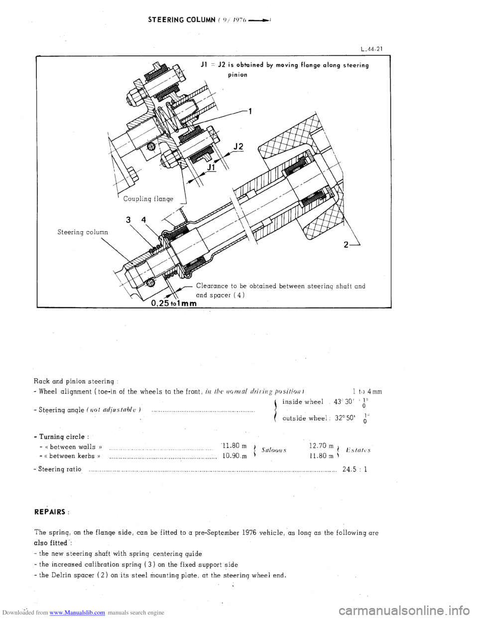
Jl = J2 is obtuined by moving flange along steering
pinion
Steering co1
Clearance to be obtained between steering shaft and
mind spacer (4)
1 a
Rack and pinion steering :
- Wheel alignment ( toe-in of the wheels to the front, i/z, /bc~ rtot~/nl rlrir,ir/g posifiort I 1 tk) 4 mm
inside wheel 43’30’
1”
- Steering angle (Ilot djustahlc~ ) 0
outside wheel : 32’50’ i’
- Turning circle :
- CC between walls )) Il.80 m
I Snloo~2 s 12.70 m
.
(! Estntc’s
- CC between kerbs )I
. . . . . ..__.._........................................,.,.. 10.90.m 11.80 m
- Steering ratio, .-.......................-............................................................................................................ 24.5 : 1
REPAIRS :
The spring, on the flange side, can be fitted to a preSeptember 1976 vehicle,‘as long as the following are
also fitted -:
- the new steering shaft with spring centerinq guide
- the increased calibration spring ( 3 ) on the fixed support side
- the Delrin spacer (2) on its steel mounting plate. at the steering wheel end.