steering wheel adjustment Citroen CX 1982 1.G Workshop Manual
[x] Cancel search | Manufacturer: CITROEN, Model Year: 1982, Model line: CX, Model: Citroen CX 1982 1.GPages: 394
Page 244 of 394

Downloaded from www.Manualslib.com manuals search engine OPERATION No MA. 4104 : (./ , k’ 1
ADJUSTMENT
NOTE The steering crossmember will have to be
moved (IS a function of the readings obtained during
checkinq
01) Towards the top to
obtain
_ toe-out ir, Ihe hish positim
- toe-in irr the 10~ psitios
b) Towards the bottom
to obtain
.
toe-in in Ihr hi& posilins
- toe-out iu fhc IOU posilios
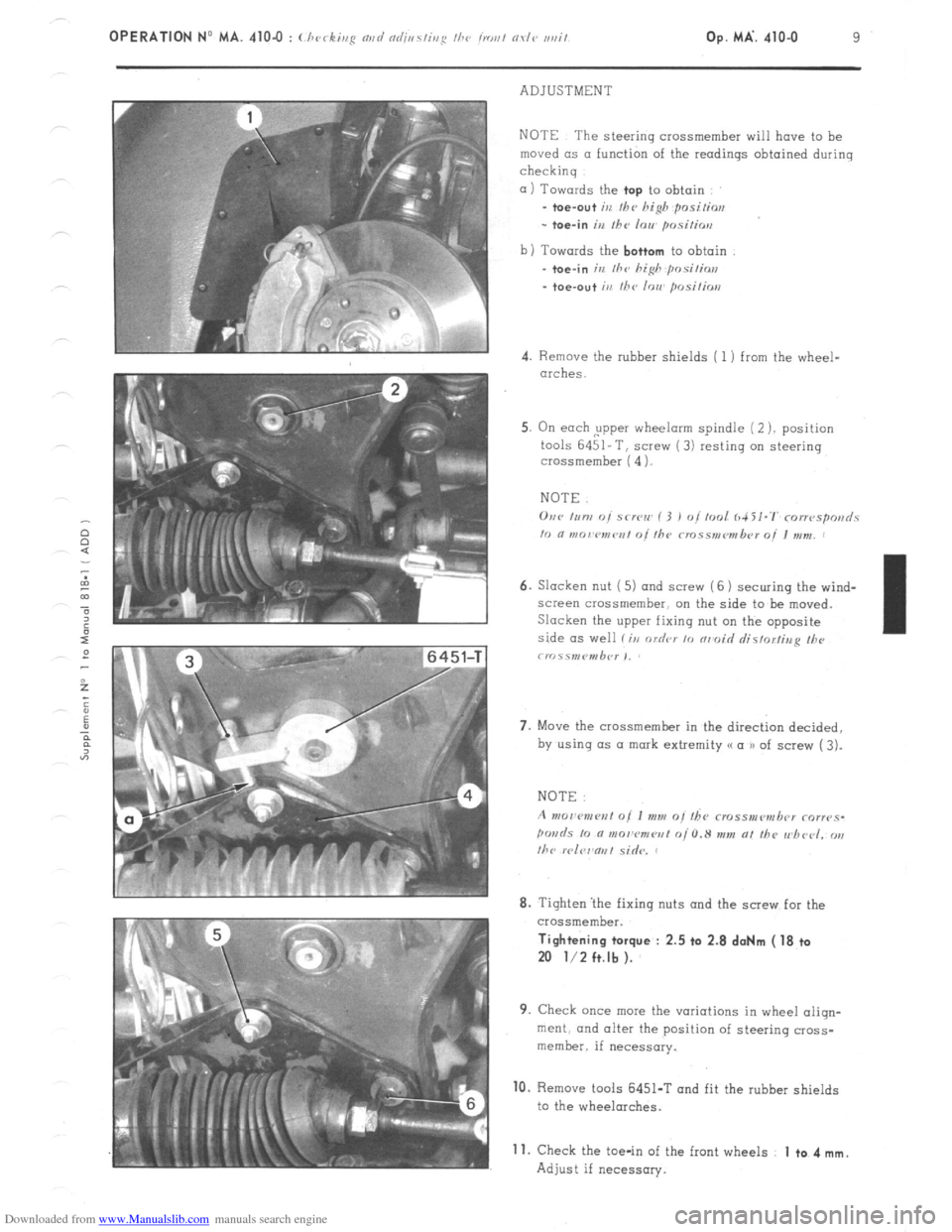
4. Remove the rubber shields ( 1 ) from the wheel-
arches.
5. On each ,upper wheelorm spindle (2 ). position
tools 6451-T, screw (3) resting on steering
crossmember ( 4 1.
NOTE.
6. Slacken nut ( 5) and screw (6 1 securing the wind-
screen crossmember. on the side to be moved.
Slacken the upper fixing nut on the opposite
side as well li,r order 10 nrmoid rlistorfina II><,
crr~.ss,nP”,b<~r ,,
7. Move the crossmember in the direct& decided,
by using (1s a mark extremity (( a u of screw ( 3).
8. Tighten ‘the fixing nuts and the screw for the
crossmember. Tightening torque : 2.5 ta 2.8 doNm ( 18 ta
20 l/2 ft.lb ).
9. Check once mew the variations in wheel aliqn-
merit. and alter the position of steering cross-
member. if necessary. 10.
Remove tools 6451-T and fit the rubber shields
to the wheelarches.
Adjust if necessary. 11.
Check the toe-in of the front wheels 1 to 4 mm.
Page 263 of 394

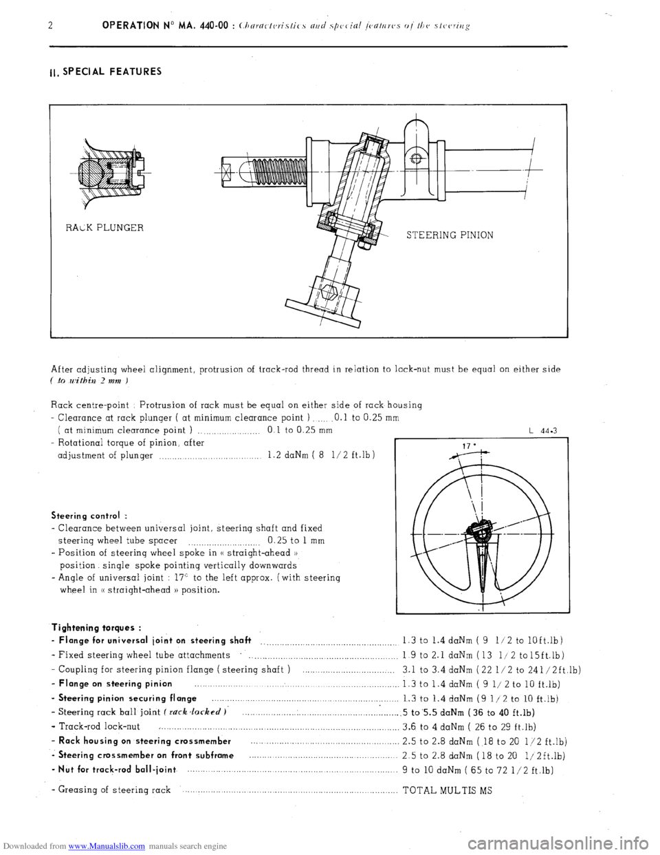
Downloaded from www.Manualslib.com manuals search engine ll, SPECIAL FEATURES
STEERING PINION
After adjusting wheel alignment, protrusion of track-rod thread in relation to lock-nut must be equal on either side
( .to within 2 mm )
Rack centre-point Protrusion of rack must be equal on either side of rack housing
- Clearance at rack plunger ( at minimum clearance point ) .O.l to 0.25
( at minimum clearance point ) ., .,...._...... .._._ 0 1 to 0.25 mm
- Rotational torque of pinion, after
adjustment of plunger .._..... .._.... 1.2 daNm ( 8 l/2 ft.lb)
L 44.3
Steering control :
- Clearance between universal joint, steering shaft and fixed
steering wheel tube spacer 0.25 to 1 mm
.._....__._..._.... ._..__..
- Position of steering wheel spoke in (( straight-ahead ))
position. single spoke pointing vertically downwards
- Angle of universal joint : 17” to the left approx. (with steering
wheel in (( straight-ahead )) position.
- Coupling for steering pinion flange ( steering shaft ) ....................................
- Flange on steering pinion ................................................................................
- Steering pinion securing flange ........................................................................
- Steering rack ball joint f rack Jacked )’ .............................................................
- Track-rod lock-nut ..............................................................................................
- Rack housing on steering crossmember ..........................................................
-. Steering crossmember on front subframe ..........................................................
- Nut for track-rod ball-joint ................. ................................... ..... ...................... Tightening torques :
- Flange for universal joint on steering shaft __..._.__.._._.........,.........................,. 1.3 to 1.4 daNm ( 9 11 2 to
lOft.lb)
- Fixed steering wheel tube attachments
. . . . . . . . . . . . . . . . . . . . . 1 9 to 2.1 daNm (13 l/2 to15ft.lb)
3.1 to 3.4 daNm (22 l/2 to 241/2ft,lb)
1.3 to 1.4 daNm ( 9 l/ 2 to 10 ft.lb)
1.3 to 1.4 daNm (9 l/2 to 10 ft.lb)
.5 to’5.5 daNm (36 to 40 ft.lb)
3.6 to 4 daNm ( 26 to 29 ft.lb)
2.5 to 2.8 daNm ( 18 to 20 l/2 ft.lb)
2.5 to 2.8 daNm (18 to 20 1/2ft.lb)
9 to 10 daNm ( 65 to 72 l/2 ft.lb)
- Greasing of steering rack TOTAL MULTIS MS
Page 272 of 394

Downloaded from www.Manualslib.com manuals search engine Op. MA. 440.00 11
2. SPECIAL FEATURES
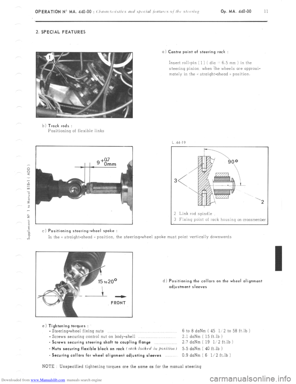
a) Centre point of steering rack :
Insert roll-pin ( 1 ) ( dio -: 6.5 mm ) in the
steering pinion when ihe wheels are appraxi-
mutely in the GG siroightohead )B position.
b 1 Track rods :
Positioning of flexible links
4J
a c) Positioning steering-wheel spoke :
2 Link rod spindle
3 Fixing point of rock housing on crossmemker
In the C( straight-ahead )) position, the steering-wheel spoke must point vertically
downwards
d) Positioning the collars on the wheel alignment
adjustment sleeves ---
FRONT
e) Tightening torques :
- Steering-wheel fixing nuts ..,.,........,......,.. .., 6 to 8 daNm ( 45 li 2 to 58 ft.lb j
- Screws securing control nut on body-shell 2.1 daNm ( 15 ft.lb )
. Screws securing steering shaft to coupling flange ,.,,.,,,,,.,.,.,,, 2.7 doNm ( 19 li2 ft.lb )
- Nuts securing flexible block on rack C rnrh lorkc~d iu psi/h) 5.5 doNm ( 40 ft.lb )
-Securing collars for wheel olignmani adjusting sleeves 0.9 daNm ( 6 l/2 ft.lb )
NOTE Unspecified tightening torques are the same as for the manual steering