ECU Citroen CX 1983 1.G Owner's Manual
[x] Cancel search | Manufacturer: CITROEN, Model Year: 1983, Model line: CX, Model: Citroen CX 1983 1.GPages: 394
Page 272 of 394
Downloaded from www.Manualslib.com manuals search engine Op. MA. 440.00 11
2. SPECIAL FEATURES
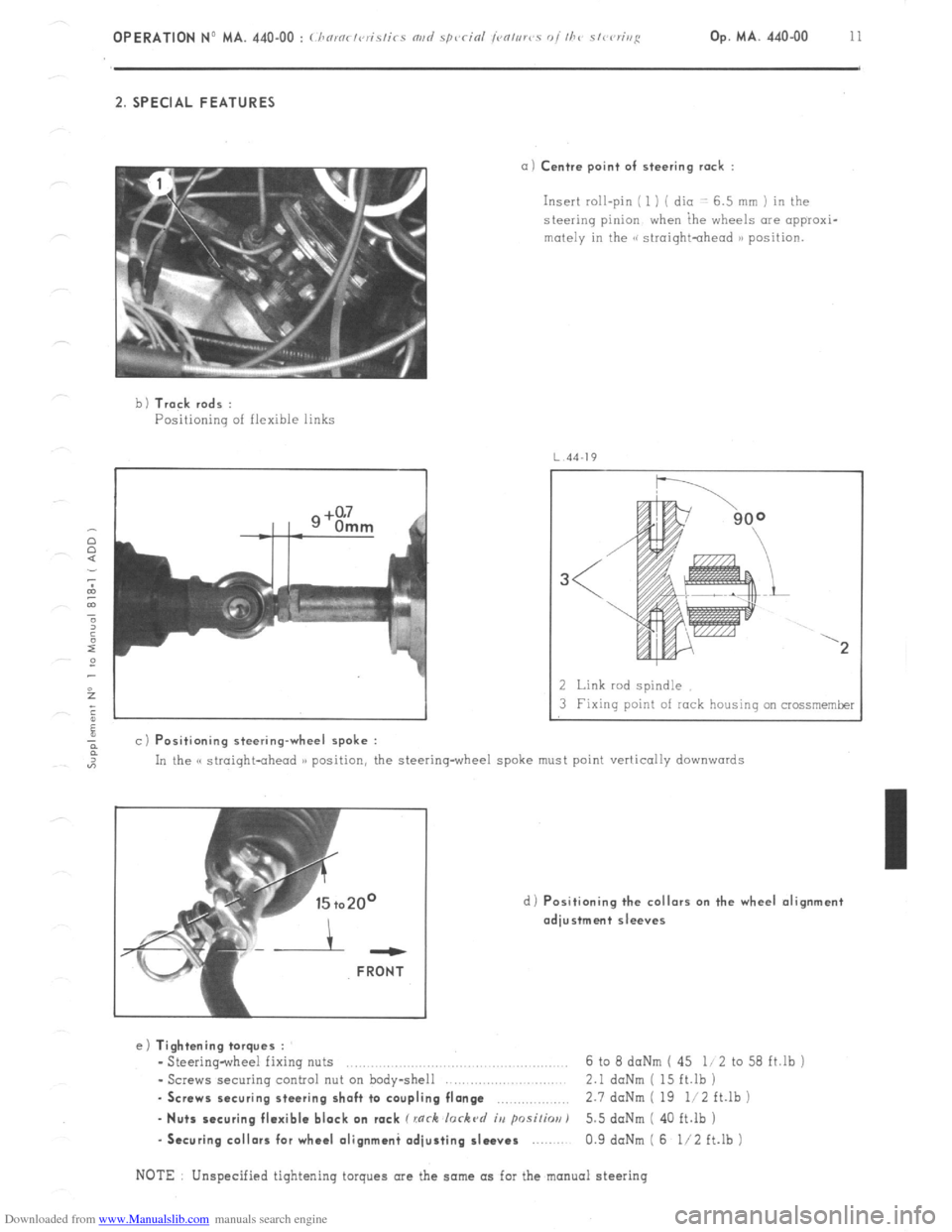
a) Centre point of steering rack :
Insert roll-pin ( 1 ) ( dio -: 6.5 mm ) in the
steering pinion when ihe wheels are appraxi-
mutely in the GG siroightohead )B position.
b 1 Track rods :
Positioning of flexible links
4J
a c) Positioning steering-wheel spoke :
2 Link rod spindle
3 Fixing point of rock housing on crossmemker
In the C( straight-ahead )) position, the steering-wheel spoke must point vertically
downwards
d) Positioning the collars on the wheel alignment
adjustment sleeves ---
FRONT
e) Tightening torques :
- Steering-wheel fixing nuts ..,.,........,......,.. .., 6 to 8 daNm ( 45 li 2 to 58 ft.lb j
- Screws securing control nut on body-shell 2.1 daNm ( 15 ft.lb )
. Screws securing steering shaft to coupling flange ,.,,.,,,,,.,.,.,,, 2.7 doNm ( 19 li2 ft.lb )
- Nuts securing flexible block on rack C rnrh lorkc~d iu psi/h) 5.5 doNm ( 40 ft.lb )
-Securing collars for wheel olignmani adjusting sleeves 0.9 daNm ( 6 l/2 ft.lb )
NOTE Unspecified tightening torques are the same as for the manual steering
Page 273 of 394
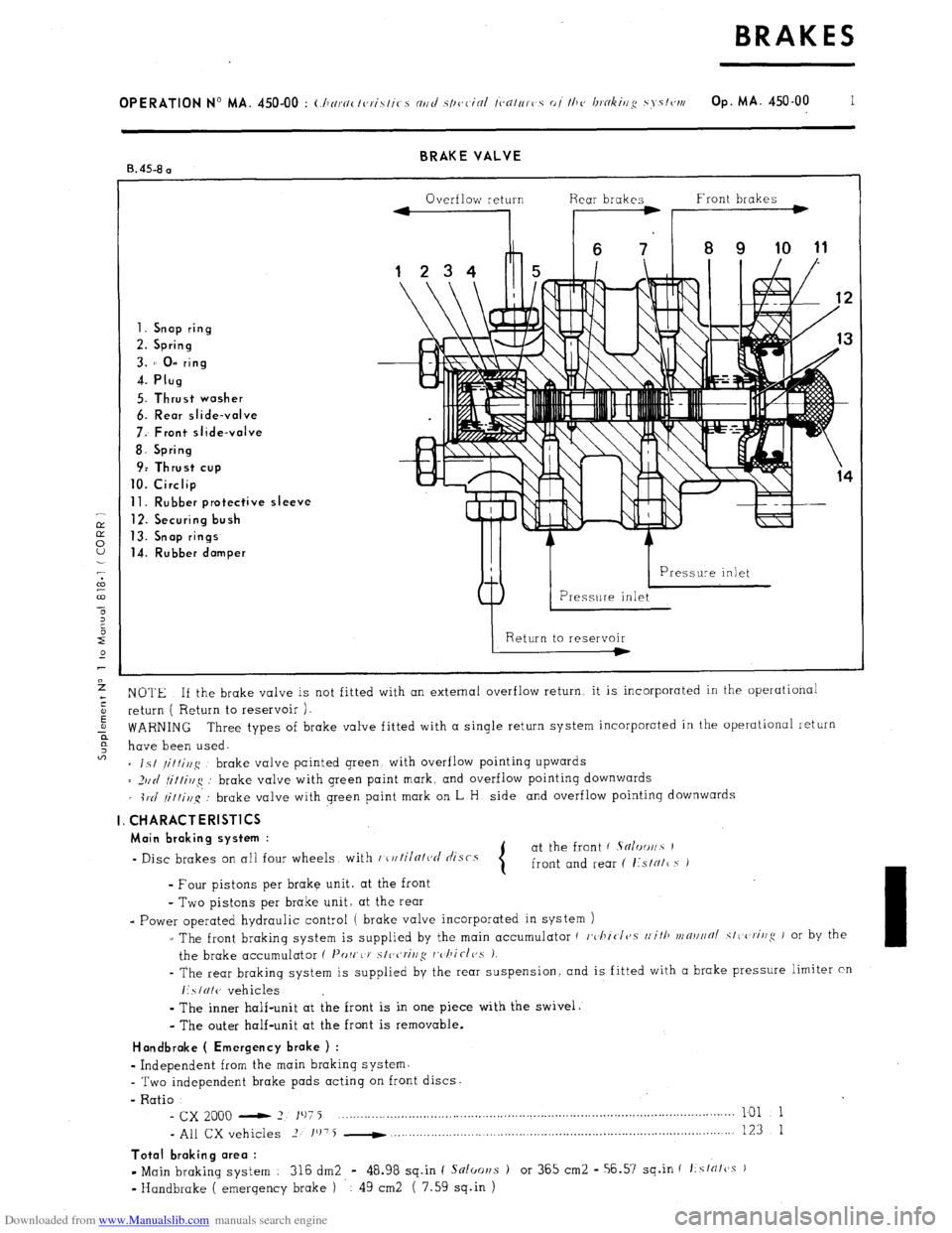
Downloaded from www.Manualslib.com manuals search engine BRAKE VALVE
B. 45-8 a
Overflow return Rear brakes Front brakes
1. Snap ring
2. Spring
3. 1’ 0” ring
4. Plug
5. Thrust washer
6. Rear slide-valve
7: Front slide-valve
8. Spring
9: Thrust cup
10. Circlip
11. Rubber protective sleeve
12. Securing bush
13. Snap rings
14. Rubber damper
NOTE If the brake valve is not fitted with an external overflow return, it is incorporated in the operational
return ( Return to reservoir ).
WARNING Three types of brake valve fitted with a single return system incorporated in the operational return
have been used.
= is/
/it/i//g brake valve painted green with overflow pointing upwards
= _)IIII
fi/tirlg : brake valve with green paint mark, and overflow pointing downwards
_ i1.d
/it/i,l~q’: brake valve with green paint mark on L H side and overflow pointing downwards
I. CHARACTERlSTlCS
Main braking system :
- Disc brakes on all four wheels with r~u/iln/ct/ tlisrs at the front ( Sn/oo//~ I
front and rear ( I:sIN/~ s i
- Four pistons per brake unit. at the front
- Two pistons per brake unit, at the rear
- Power operated hydraulic control ( brake valve incorporated in system )
z The front braking system is supplied by the main accumulator ( c,~l~icI~~.s
rli/ll vrn~l//~/ SIC criug J or by the
the brake accumulator ( I’orr,< J’
s/ccrivg rc,/~iclc,s 1.
- The rear braking system is supplied by the rear suspension. and is fitted with a brake pressure limiter cn
I:SIUI(J vehicles
-
The inner half-unit at the front is in one piece with the swivel.
- The outer half-unit at the front is removable.
Handbroke ( Emergency brake ) :
w
Independent from the main braking system.
- Two independent brake pads acting on front discs.
- Ratio
- cx 2000 - 2 197 j ___._....._..._..._.........,............................................................................... 101 1
- All CX vehicles 2 1’j75 -
. . . . . . 123 1
Total braking area :
- Main braking system : 316 dm2 - 48.98 sq.in ( Snloor~s ) or 365 cm2 - 56.57 sq.in f f:sfrffcss )
v
Handbrake ( emergency brake ) 49 cm2 ( 7.59 sq.in )
Page 277 of 394
Downloaded from www.Manualslib.com manuals search engine OPERATION No MA. 450-00 : Ch nrnclcrislics ortd sp~~c-i~l (c~c~trlrc>s 01 the hokiug S SI~IN Op. MA. 450.00 5
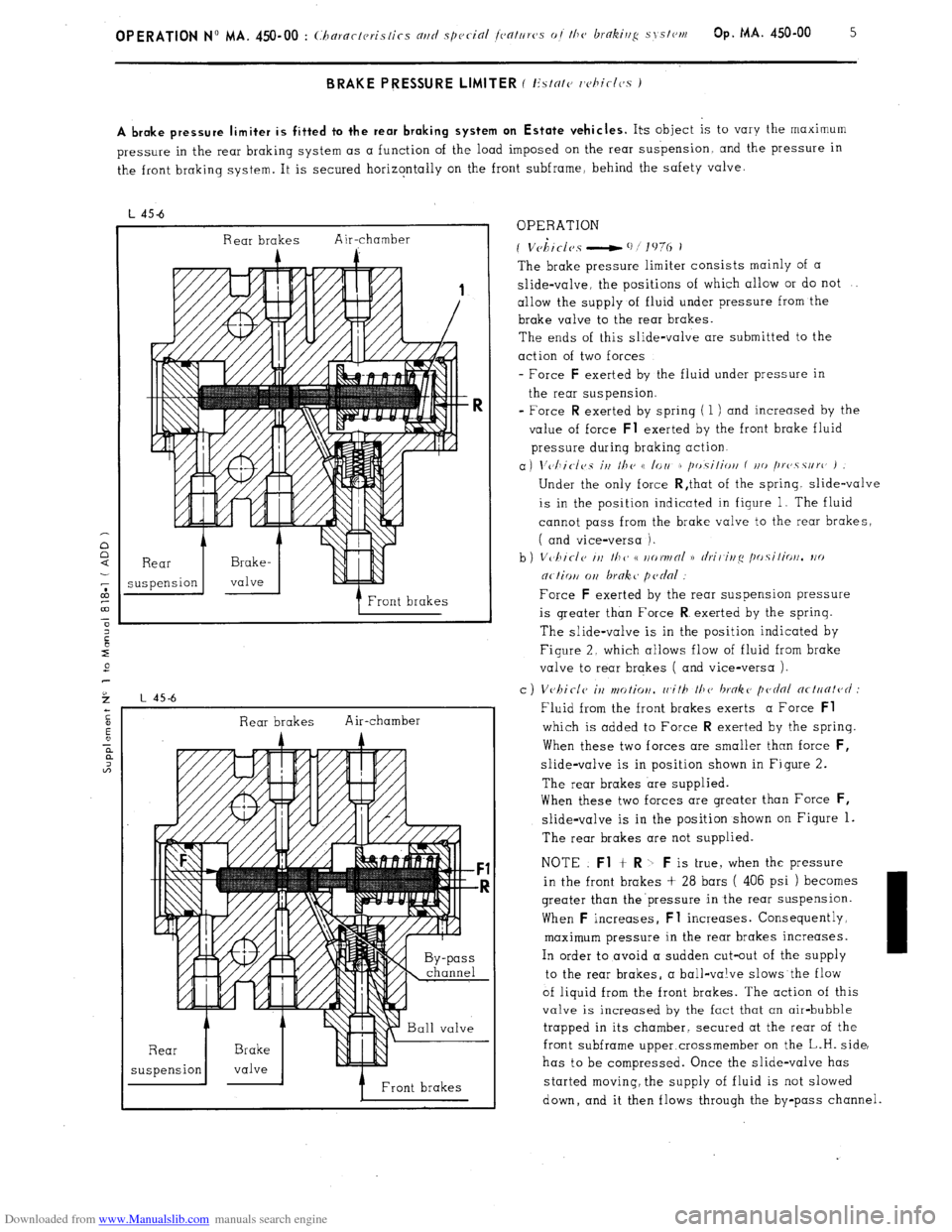
A brake pressure limiter is fitted to the rear braking system on Estate vehicles.
Its object is to vary the maximum
pressure in the rear braking system as a function of the load imposed on the rear suspension and the pressure in
the front braking system. It is secured horizontally on the front subframe, behind the safety valve.
L 45-6
Rear brakes Air-chamber
A
Front brakes
Rear brakes Air-chamber
A A --
7 Front brakes OPERATION
* I
f Vchtclcs - ‘I/]‘,?(, i
The brake pressure limiter consists mainly of a
slide-valve, the positions of which allow or do not
allow the supply of fluid under pressure from the
brake valve to the rear brakes.
The ends of this slide-valve are submitted to the
action of two forces
- Force F
exerted by the fluid under pressure in
the rear suspension.
= Force R
exerted by spring ( 1 ) and increased by the
value of force Fl
exerted by the front brake fluid
pressure during braking action.
a) \‘~~I~i~-/~~s irt Ilte t( lorl r /tr,.silioti f t/o /trc~.s.surc’ )
Under the only force R,that of the spring. slide-valve
is in the position indicated in figure 1. The fluid
cannot pass from the brake valve to the rear brakes,
( and vice-versa ).
Force
F exerted by the rear suspension pressure
is greater than Force R
exerted by the sprinq.
The slide-valve is in the position indicated by
Figure 2. which allows flow of fluid from brake
valve to rear brakes ( and vice-versa ).
c ) Vvhiclc il2 ntotior/. rr,ith 111~’ broke pednl ncl~~fit~~c/ :
Fluid from the front brakes exerts a Force Fl
which is added to Force R exerted by the spring.
When these two forces are smaller than force F,
slide-valve is in position shown in Figure 2.
The rear brakes are supplied.
When these two forces are greater than Force
F,
slide-valve is in the position shown on Figure 1.
The rear brakes are not supplied.
NOTE Fl
+ R -b F is true, when the pressure
in the front brakes + 28 bars ( 406 psi ) becomes
greater than the’pressure in the rear suspension.
When F
increases, Fl increases. Consequently,
maximum pressure in the rear brakes increases.
In order to avoid a sudden cut-out of the supply
to the rear brakes, a ball-valve slows the flow
of liquid from the front brakes. The action of this
valve is increased by the fact that an air-bubble
trapped in its chamber, secured at the rear of the
front subframe upper.crossmember on the L.H. side,
has to be compressed. Once the slide-valve has
started moving, the supply of fluid is not slowed
down, and it then flows through the by-pass channel.
Page 281 of 394
Downloaded from www.Manualslib.com manuals search engine OPERATION No MA. 450-00 : (:/~ornc.t(,ris/i(- c/r/d ,S/ICJC inl /c,c//r~rc,s ot the brcrkillg s~‘.stc~rt~ Op. MA. 450-00 9
Handbroke ( Emergency broke )
- Thickness of the lininq on one pad
4.15 mm _...... .._.......... _.. .,..........
- Type of lining .__............................._....._._..... .._.... .._.. .._.
TEXTAR T 270
- Area of one pad
._..
12 cm2 ( 1 86 sq in )’
- Adjusting the -pads the pads must just contact the disc at its highest points.
Tightening torques :
- Flexible brake pipe on front brake unit tube .............. ..... ....... ........... ........ 3 6 to 4daNm (26 to 29 ft.lb )
- Nut securing front brake pipe on subframe .................................................
2.1 to 2 4daNm (15 to 17 1/2ft.lb )
- Brake valve securing point .................. .............................. ........... ........ 1 8 daNm ( 13 ft.lb )
. Pedal assembly securing point .....................
...... ..................................
0 5 daNm ( 3 l/2 ft.lb )
Page 282 of 394
Downloaded from www.Manualslib.com manuals search engine OPERATION No MA. 451-O : Uwckirrg the hrflkv rov,~o,rrnts Op. MA. 451.0 1
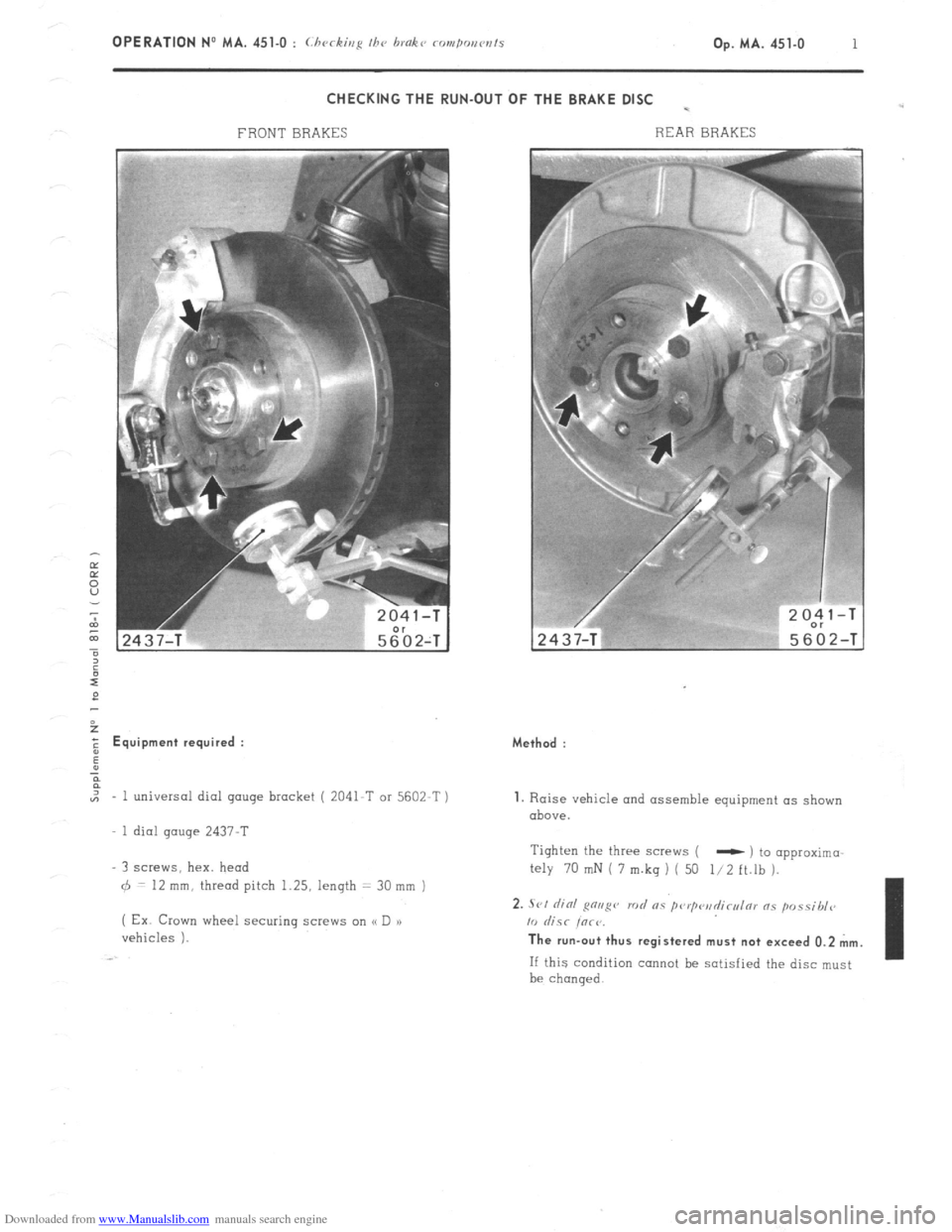
CHECKING THE RUN-OUT OF THE BRAKE DISC -
FRONT BRAKES REAR BRAKES 2
E Equipment required :
,,, - 1 universal dial gauge bracket ( 2041-T or 5602-T )
1 dial gauge 2437-T
3 screws, hex. head
6 = 12 mm, thread pitch 1.25, length = 30 mm )
( Ex Crown wheel securing screw on (< D a)
vehicles ). Method :
1. Raise vehicle and assemble equipment as shown
above.
Tighten the three screws (
- ) to opproximo
My 70 mN i 7 m.kq ) ( 50 l/2 ft.lh ).
2. .Sl,l did g”“g” rod RS pwp<‘il~cl,l171 ns p”ssibl<~
10 &SC iorr. The run-out thus registered must not exceed 0.2 mm.
If this condition cannot be satisfied the disc must
be chanqed.
Page 359 of 394
Downloaded from www.Manualslib.com manuals search engine OPERATION No MA. 560.0 : ~hrrkin~ o,,d oc/@s/i,,g I/><, wiurisrrrr,, wip’r. Op. MA. 560.0
1
Fi
m
0 CHECKING AND ADJUSTING THE WINDSCREEN WIPER.
FRONT WINDSCREEN WIPER MOTOR
CHARACTERISTICS.
Manufacturer DUCELLIER
Reference No. 4966 A
Field coils Ferrite
Armature : Endfloot (adjustable by means of stop-screw) : 0.2 mm
Nominal dia. of commutator :
24 mm
Min. dia. after machining : 23 mm
Brushes : Ref. No. :
CL 7239
Minimum length after wear : 5.5 mm
Ratio : .._...................................................................................................
44 1
Connection and circuit diagram as in Op. MA. 510 00.
ELECTRICAL CHECK. BOSCH
0390 346 127
Ferrite
0
23.2 mm
23 mm
1.394.320-058 059, 062
7.5 mm
49 1
1. First speed :
Nominal power : IO watts
Speed, under no load, at 13.5 volts = 50 rpm Corresponding current = I.8 A
Torque, motor locked, at 13.5 volts = 1.9 da Nm 7 13.74 ft.lb min. Corresponding current 18 A max.
Torque at 40 rpm and 13.5 volts = 0.2 do Nm (1.45 ft.lb) Correspondinq current = 5.5 A max.
- Torque ot 20 rpm and 13.5 volts = 1.07 da Nm (7.74 ft.lb) min Corresponding current = 13.2 A max.
2. Second speed :
Nominal power : 15 watts
Speed under no load at 13.5 volts = 70 rpm Corresponding current = 2.3 A
Torque motor locked at 13.5 volts = 1.5 do Nm (IO.85 ft.lb) min Corresponding current = 21 A max
Torque at 60 rpm and 13.5 volts = 0.2 da Nm (1.45 ft.lb) min Corresponding current = 7 A max
Torque ot 30 rpm and 13.5 volts = 0.9 da Nm (6.51 ft.lb) min Corresponding current = 14.7 A mrx.
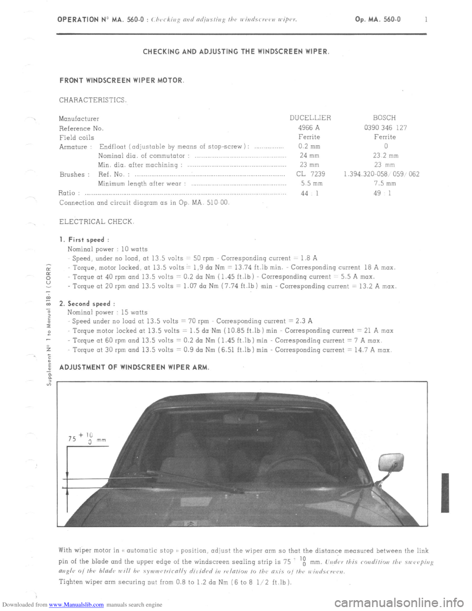
ADJUSTMENT OF WINDSCREEN WIPER ARM
With wiper motor in (< automatic stop )/ position, adjust the wiper arm so that the distance measured between the link
pin of the blade and the upper edge of the windscreen sealing strip is 75 ‘t
mm. L’vd‘ar /his rondiliw, /he 51, rvp;,,g
m,g/r 0, /he bladr ,,~i// hv symv,r~/rirn//v dil idrd it, w/n/io,, 10 /he O.YiS “, I/w r,‘iri
Tighten wiper arm securing out from 0.8 to 1.2 da Nm (6 to 8 l/2 ft.lb).
Page 362 of 394
Downloaded from www.Manualslib.com manuals search engine II. OPERATING PRINCIPLE
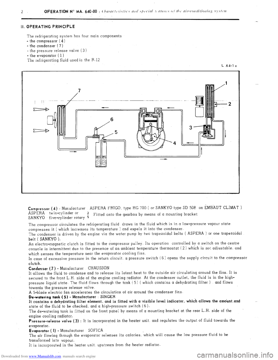
The refrigerating system has four main components
- the compressor ( 4)
- the condenser ( 7)
- the pressure release valve (3 i
*
the evaporator ( 1 )
The refrigerating fluid used is the F. 12
L.64.1 a
Compressor
(4) - Manufacturer ASPERA FRIGO. type HG 700 ( or SANKYO type SD 508 on EMBAUT CLIMAT )
ASPERA twin-cylinder or
SANKYO five-cylinder rotary 1 Fitted onto the gearbox by means of a mounting bracket
The compressor circulates the refrigerating fluid draws in the fluid which is in a low-pressure vapour state
compresses it ( which increases its temperature ) and expels it into the condenser.
The condenser is driven by the engine via the water pump by two trapezoidal belts ( ASPERA ) or one trapezoidal
belt ( SANKYO ).
An electro-magnetic clutch is fitted to the compressor pulley. Its operation controlled by a switch on the centre
console is intermittent due to the presence of an ambient temperature thermostat ( 2 ) which is not adjustable, and
which senses the temperature near the evaporator cooling fins.
In case of excessive pressure in the return circuit, a pressure switch (6) opens the supply circuit to the compressor
clutch.
Condenser (7 ) - Manufacturer CHAUSSON
It allows the fluid to condense and to release its latent heat to the outside air circulating around the fins. It is
secured to the front L.H. side of the engine cooling radiator At the condenser outlet, the fluid is in the high-
pressure liquid state. The fluid flows through the tank ( 5) ( which contains a dehydrating filter ) and flows
towards the pressure release valve.
A 5-blade electric fan accelerates the circulation of air around the condenser fins.
De-watering tank .( 5) - Manufacturer : SINGER
It contains a dehydrating filter element, and is fitted with a visible level indicator, which allows the amdunt .and
state of the fluid to be checked, and a high-pressure switch (6).
The de-watering tank is fitted on the front panel by means of a mounting bracket at the rear L.H. side of the
engine cooling radiator.
Pressure-release valve (3) : It is incorporated in the heater unit, and regulates the output of fluid towards the
evaporator.
Evaporator ( 1) - Manufacturer SOFICA
The air flowing through the evaporator releases its calories, ‘which will cause the low pressure fluid to be
transformed into vapour.
It is incorporated in the heater unit upstream from the heater radiator.
Page 385 of 394
Downloaded from www.Manualslib.com manuals search engine 2 OPERATION NO MA. 841-O : Adjmfing /he o’r,ors
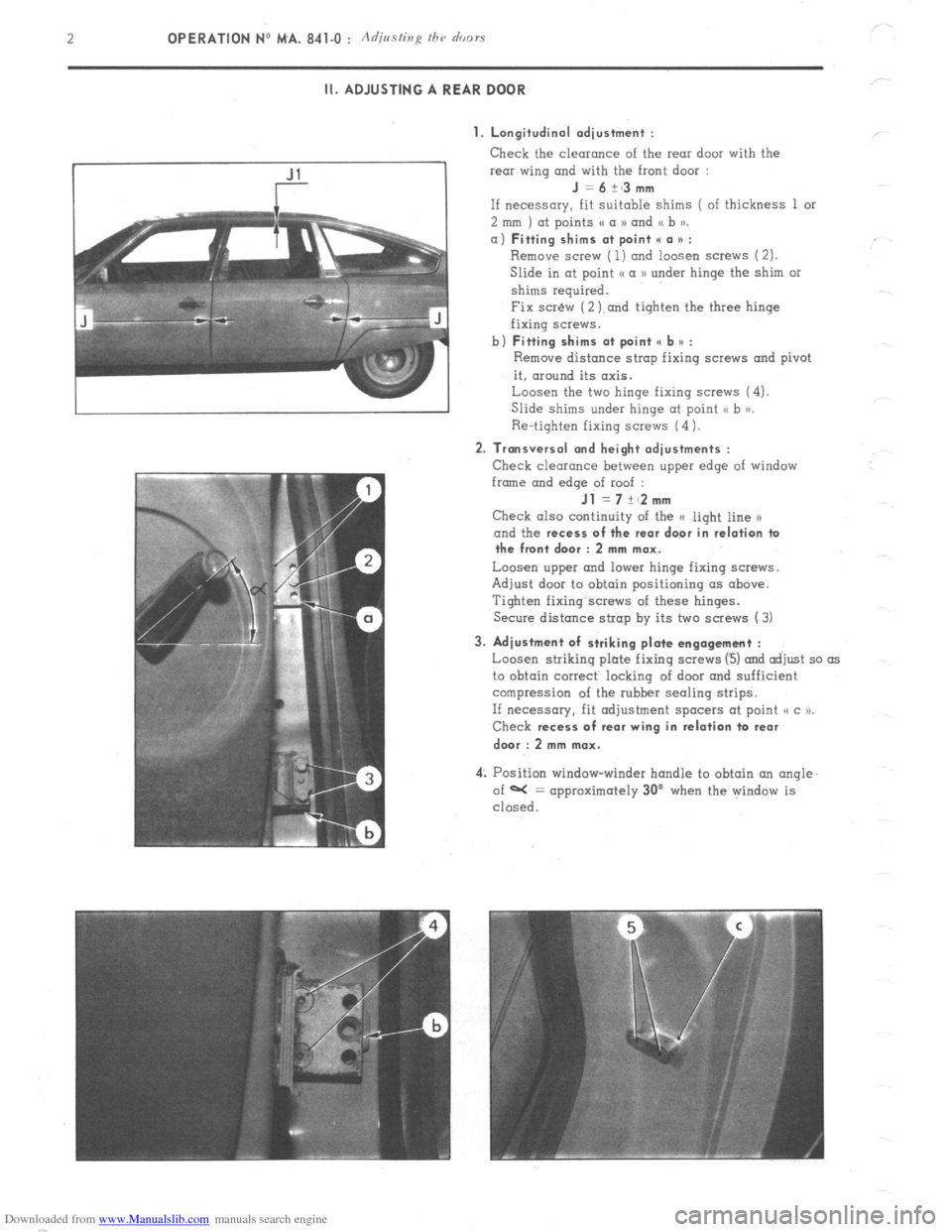
II. ADJUSTING A REAR DOOR
1. Longitudinal adjustment :
Check the clearonce of the rear door with the
rear wing and with the front door :
J =6+~3mm
If necessary, fit Suitable shims ( of thickness 1 or
2 mm ) at points (( a N and (( b )).
a) Fitting shims at point II a * :
Remove screw ( 1) ond loosen screws (2).
Slide in at point I< a D under hinge the shim or
shims required.
Fix scr&v (2 ).and tighten the three hinge
fixing screws.
b)
Fitting shims at point e b u :
Remove distance strop fixing screws and pivot
it, around its axis.
Loosen the two hinge fixing screws (4).
Slide shims under hinge at point <, b >j.
Re-tighten fixing screws (4 1.
2. Transversal and height adjustments :
Check clearance between upper edge of window
frmne and
edqe of roof :
Jl =7+~2mm
Check also continuity of the G light line x
and the recess
of the rear door in relation ta
the front door : 2 mm max.
Loosen upper and lower hinge fixing screws.
Adjust door to obtain positioning (IS above.
Tighten fixing screws of these hinges.
Secure distance strap by its two screws (3)
3. Adjustment of striking plate engagement :
Loosen striking plate fixing screws (3) and adjust so as
to obtain correct locking of door and sufficient
compression of the rubber sealing strips.
If necessary, fit adjustment spacers at point o c u.
Check recess
of rear wing in relation ta rear
dwr : 2 mm max.
4: Position window-winder handle to obtain an angle.
of W = approximately 30’ when the window is
closed.
Page 387 of 394
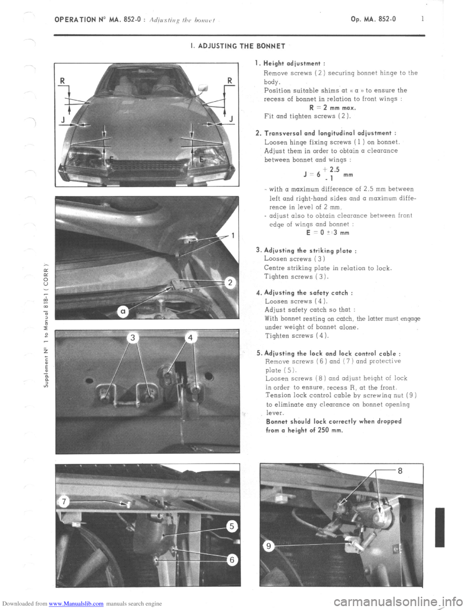
Downloaded from www.Manualslib.com manuals search engine OPERATION No MA. 852-O : Adius/ir,y I/><, bo,,r,r/ Op. MA. 852-O 1
~.
I. ADJUSTING THE BONNET
I. Height adjustment :
Remove screws (2) securing bonnet hinge to the
body.
Position suitable shims at u a )) to ensure the
recess of bonnet in relation to front wings : R = 2 mm max.
Fit and tighten screws (2 ). 2. Transversal and longitudinal adjustment :
Loosen hinge fixing screws ( 1 ) on bonnet
Adjust them in order to obtain a clearance
between bonnet and wings : J=6
+ 2.5
-1 mm
- with (I maximum difference of 2.5 mm between
left and right-hand sides and a maximum diffe-
rence in level of 2 mm,
- adjust also to obtain clearance between front
edge of wings and bonnet : E = 0 it3 mm
3. Adjusting the striking plate :
Loosen screws ( 3 )
Centre striking plate in relation to lock.
Tiqhten screws ( 3 ). 4. Adjusting the safety catch :
Loosen screw5 (4 1.
Adjust safety catch so that :
With bonnet resting on catch, the latter must engage
under weight of bonnet alone.
Tighten screws (4 ). 5. Adjusting the lock and lock control cable :
Remove scravs (6 ) and (7 ) and protective
plate (5).
Loosen screws (8) and adjust height of lock
in order to ensure, recess R, at the front.
Tension lock control cable by screwing nut (9 )
to eliminate any clearance on bonnet opening
leV%. Bonnet should lock correctly when dropped
from (I height of 250 mm.
Page 389 of 394
Downloaded from www.Manualslib.com manuals search engine OPERATION No MA. 961-O : C/ 3fc ztzg and repairing a war winabzc’ hrating elcmcnt k’ Op. MA. 961-O 1
I. CHECKING
Power of heating resistance :
S&Ions ., 140 to 160 watts at 13.5 1: 0.2 volts
Estates .,.,............: . . . . . . . .._.... . . . . . . . . . . . . . . . . . . . . . . . . . . . . . . . . . . . . . . . . . . . . . . . . . . . . . . . ~.. 130 to 150 watts at 13.5 t 0.2 volts
To check :he heating resistance of a rear window. measure
Either the current flowing in the resistance, using an ammeter connected in series to the supply lead of
the element. The current should be :
Saloons ,..., ., ,. ,. ,..,. ,,., ,,,., _, ,. .,., ..l_. 9.2 to 10.6 amps at 12 volts
Estates . . .., ,,..._.__.. .:_._ ._ . ..8 5 to 9.8 amps at 12 volts
Or the resistance using an ohmmeter. Resistance should be :
Saloons . . . . . . . . . . . . . . . . . . . . . . . . . . . . . . . . . j _..__.._....,. 1.1 to 1.3Q
Estates . .._...........,.,.,...,.....,..,..................................,,..,.,.,.,........,. 1 .2 to 1.4 !J
II. REPAIRING
1. Replacement of terminals : Tin that part of the terminal to be soldered. Solder it in the required location ( soldering iron ).
2. Repairing a section of the heating element : a) Obtain from the Replacement Parts Department :
- 1 Repair kit .,,..,,..,,.,.,.,.,,,.,.,,....,................,,,,,...,., ZC. 9 855 128 U
This M SECURIGLACE ))‘outfit includes :
- 1 Bottle of abrasive cleaning powder
- 1 Small bottle of conductive enamel
- 1 Tube of adhesive
- 1 Tube of hardener for adhesive
- 1 Small bottle of metallic powder
- 1 Roll of thick self-adhesive tape
- 1 Warning lamp for detecting cuts
- 1 Roll of self-adhesive tape for detecting cuts ( thermopaper )
- 1 Plastic spatula
- 1 Small glass plate ( for preparation of mixtures )
b)
Locating the cut : With the resistance fed as normal :
- Locate the defective resistance wire by sticking the adhesive detection tape at the centre of the rear
window ( interior side ) and on all resistance wires so that the tape is perpendicular to the latter.
The unbroken wires will turn the thermo-paper blue when they increase in temperature.
- Slide the two pointed probes of the warning lamp support on the cut wire. When the lamp lights up,
the pointed probes are on both sides of the break in the wire.
By slightly moving the probes along the length of the wire, the exact extent of the cut can be determined.