diagram Citroen CX 1983 1.G Service Manual
[x] Cancel search | Manufacturer: CITROEN, Model Year: 1983, Model line: CX, Model: Citroen CX 1983 1.GPages: 394
Page 321 of 394
Downloaded from www.Manualslib.com manuals search engine 10 OPERATION No MA. 510-00 b : A ,tnrt
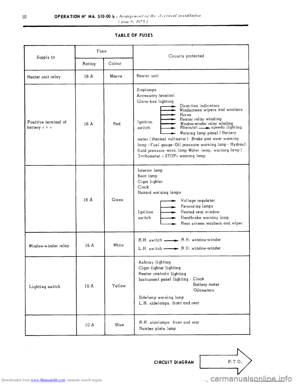
( O.fjtft 91 107 5 ) TABLE OF FUSES
Supply to
I
Fuse
Circuits protected
Rating Colour
Heater unit relay 16 A Mauve Heater unit
Positive terminal of
battery (( + u 16
A Red Stoplamps
Accessory terminal
Glove-box lighting
E Direction indicators
Windscreen wipers and washers
Horns
Ignition
SW itch
Warning lamp panel ( Battery
meter ( thermal voltmeter ) -Brake pad wear warning
lamp -Fuel gauge- Oil pressure warning lamp - Hydraul.
fluid pressure warn. lamp-Water temp. warning lamp )
Tachometer, (( STOP)) warning lamp
16 A Green Interior lamp
Boot lamp
Cigar lighter
Clock
Hazard warning lamps
Voltage regulator
Reversing lamps
Ignition Heated rear window
switch
E Handbrake warning lamp
Rear screen washers and wiper
Window-winder relay
Lighting switch 16 A
10 A White
Yellow R.H. switch - R.H. window-winder
L.H. switch - R H. window-winder
Ashtray lighting
Cigar-lighter lighting
Heater controls lighting
Instrument panel lighting : Clock
Battery meter
Odometers
Sidelamp warning lamp
L.H. sidelamps, front and rear
10 A Blue R.H. sidelamps. front and rear
Number plate lamp Cl RCU IT DIAGRAM
Page 325 of 394
Downloaded from www.Manualslib.com manuals search engine 12 OPERATION No MA. 510-00 b : .A rlan ement oi the CIerlrical iustallatiw
I:
( from 9/ 1075 i
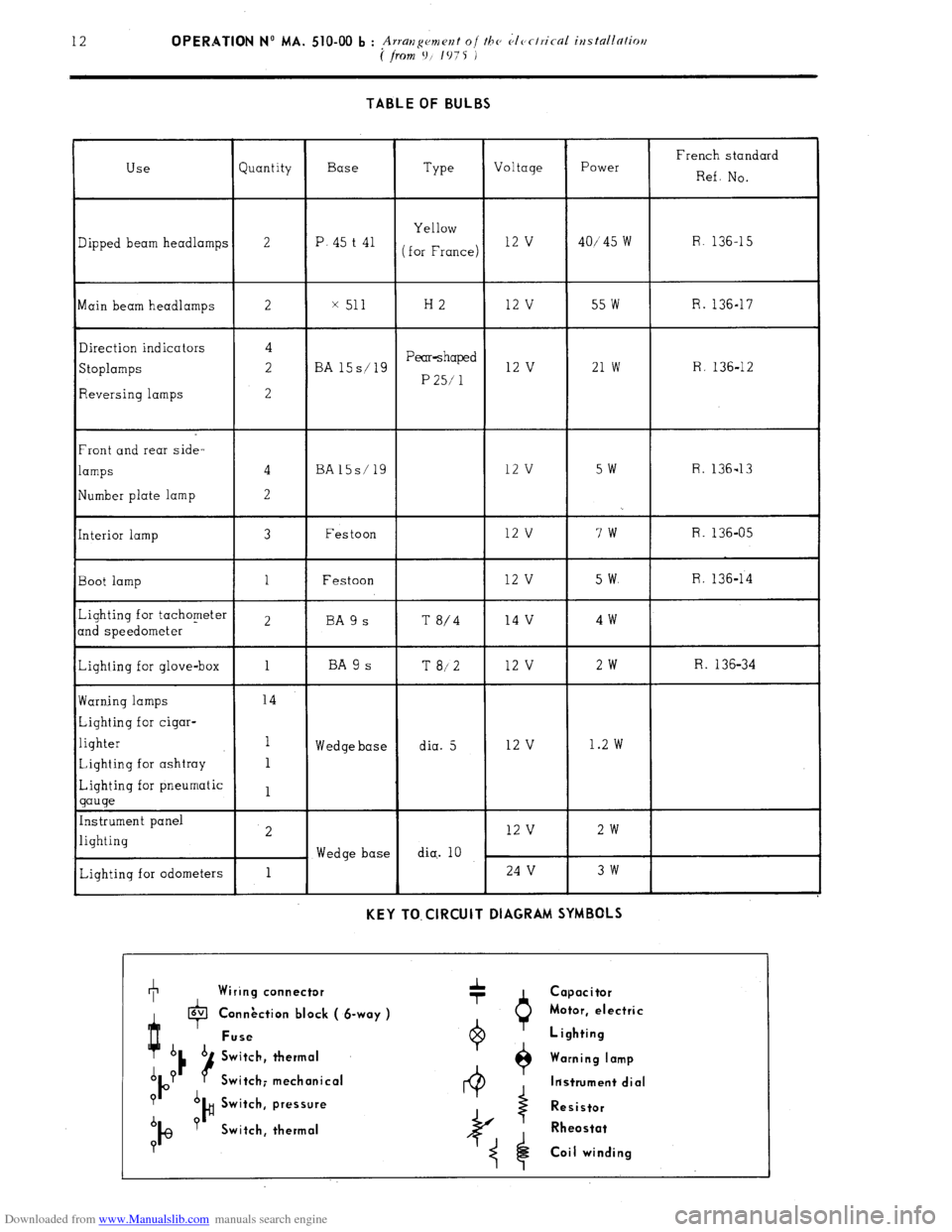
TABLE OF BULBS
Use Quantity Base
Type Voltage Power French standard
Ref. NO.
Yellow
3ipped beam headlamps 2 P. 45 t 41
(for France) 12 v 40/‘45 w R. 136-15
Main beam headlamps 2 x 511 H2 12 v 55 w R. 136-17
Direction indicators 4
Stoplamps 2 BA 15s/19 Pear-shaped 12 v 21 w R. 136-12
P 25/ 1
Reversing lamps 2
Front and rear side-
lamps 4 BA15s/19 12 v SW R. 136-13
!Iumber plate lamp 2
[nterior lamp 3 Festoon 12 v 7w R. 136-05
Boot lamp 1 Festoon 12 v 5 w. R. 136-14
Lighting for tachometer
2 BA 9 s T
md speedometer 8/4 14 v 4w
Lighting for glove-box 1 BA 9 s T 8/2 12 v 2w R. 136-34
Warning lamps 14
Lighting for cigar-
lighter 1
Wedge base dia. 5 12 v 1.2 w
Lighting for ashtray 1
Lighting for pneumatic
1
gauge
Instrument panel
lighting 2 12 v 2w
Wedge base dia.. 10
Lighting for odometers 1 24 v 3w
KEY TO. ClRCUlT DIAGRAM SYMBOLS +
, Wiring connector
I lavl
P
Connection block ( &way ) Connection block ( &way )
Fuse Fuse
A Switch, thermal
A P
P Switch; mechanical Switch; mechanical
? A
b ?
I@ )# Switch, pressure Switch, pressure
Switch, thermal Switch, thermal
? Capacitor
Motor, electric
Lighting
Warning lamp
ltistrument dial
Resistor
Rheostat
Coil winding
Page 329 of 394
Downloaded from www.Manualslib.com manuals search engine TORQUE CONVERTER ( I ‘/+(I -I
1 51-Rh
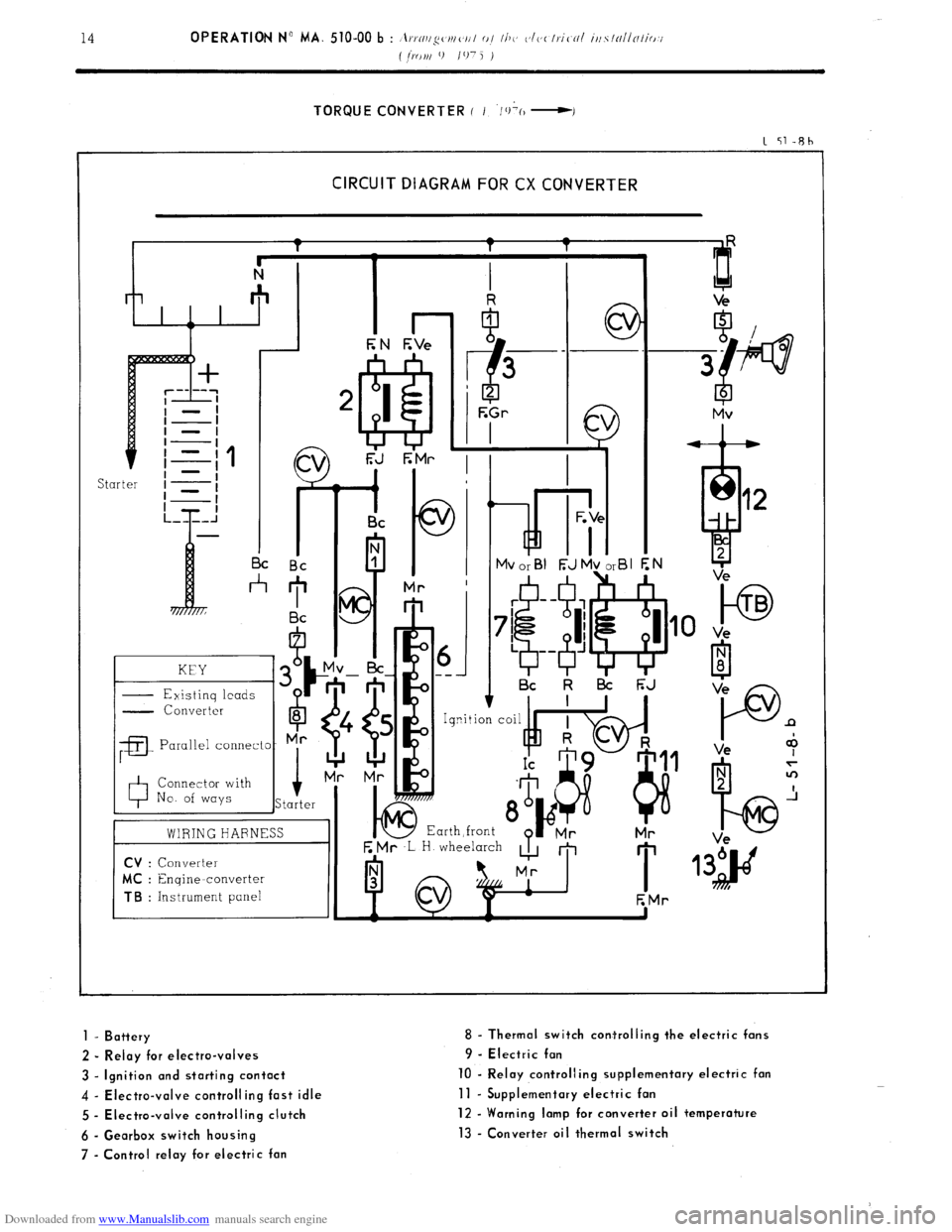
CIRCUIT DIAGRAM FOR CX CONVERTER
kd i- I I I c
I I Bc Bc
*
KEY
- Existinq leads G
- Converter
6
8
;a
Parallel connecto- Mr
0 Connector with
No. of ways i
Starter
01 ---
I Bc k l3i F;J
E Mr ,L H wheelarch
A m
I 1
EMr
to TB
Ve
P n
Ve +
1 - Battery
2 - Relay for electro-valves
3 - Ignition and starting contact
4 - Electra-valve controlling fast idle
5 - Electra-valve controlling clutch
6 - Gearbox switch housing
7 - Control relay for electric fan 8 - Thermal switch corrtrolling the electric fans
9 - Electric fan
10 - Relay controlling supplementary electric fan
11 - Supplementary electric fan
12 - Warning lamp for converter oil temperature
13 - Converter oil thermal switch
Page 330 of 394

Downloaded from www.Manualslib.com manuals search engine OPERATION No MA. 510-00 b : , ,rn,l~~~‘Nl(‘Il I 0 / Ill C’ c~/~~tl,.ifNI ir/.YlnllalitM/
( j,arv 9 107j I
. Op. MA. 510-00 b
15
CIRCUIT DIAGRAM
Page 331 of 394
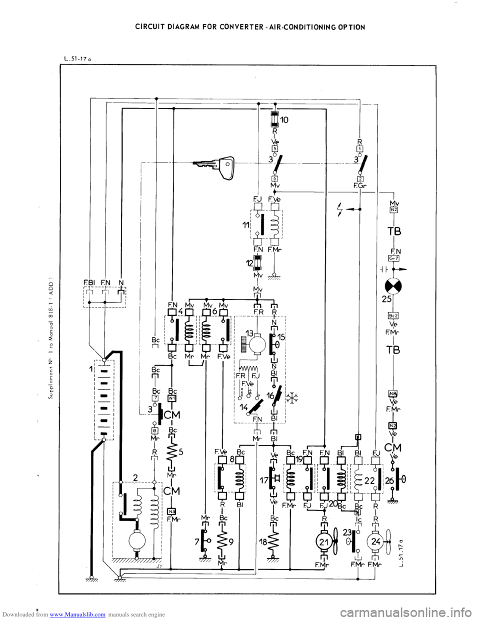
Downloaded from www.Manualslib.com manuals search engine CIRCUIT DIAGRAM FOR CONVERTER -AIR-CONDITIONING OPTION
L.Sl-170
Page 333 of 394
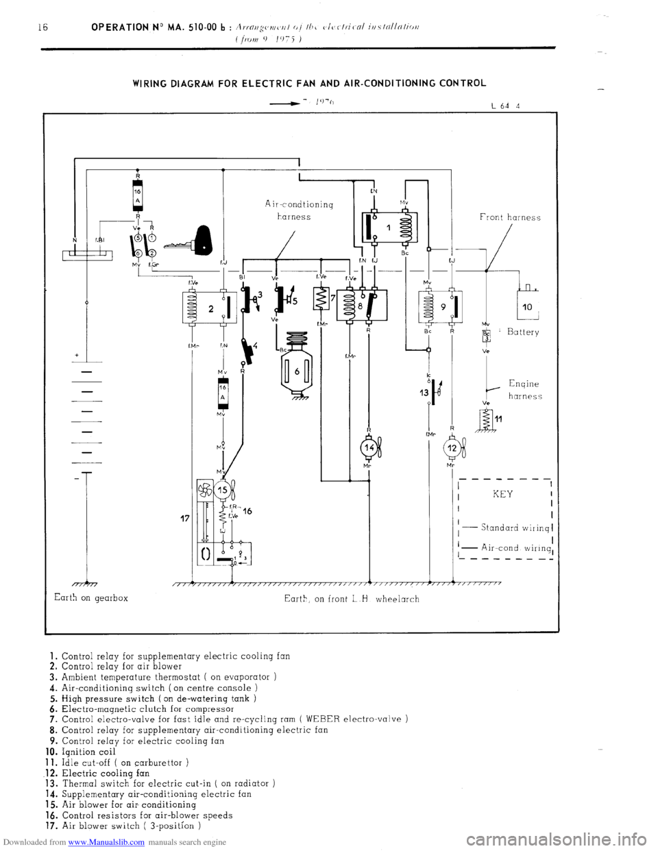
Downloaded from www.Manualslib.com manuals search engine WIRING DIAGRAM FOR ELECTRIC FAN AND AIR-CONDITIONING CONTROL
-- I’)‘(,
L64 4
41 1 1 Front harness
-
T
17
I KEY I
I I
I
Standard wiiinq I
I I
I I
I - Air-cond wiIinq, ‘- - - - - - - _-
1 i 1 1 1
/,/r/////,/,,,,/,//////~////~‘/‘~””’~”””””~””7”“““’
Earth on gearbox
Eart>, on front L H wheelarch 1.
Control relay for supplementary electric cooling fan
2. Control relay for air blower
3. Ambient temperature thermostat ( on evaporator )
4. Air-conditioning switch (on centre console )
5. High pressure switch ( on de-watering tank )
6. Electra-magnetic clutch for compressor
7. Control electro-valve for fast idle and re-cycling ram
( WEBER electro-valve )
8. Control relay for supplementary air-conditioning electric
9. Control relay for electric cooling fan 10.
Ignition coil 11.
Idle cut-off ( on carburettor ) .12.
Electric cooling fan
13. Thermal switch for electric cut-in ( on radiator )
14. Supplementary air-conditioning electric fan
15. Air blower for air- conditioning 16.
Control resistors for air-blower speeds 17.
Air blower switch ( 3-position )
Page 334 of 394
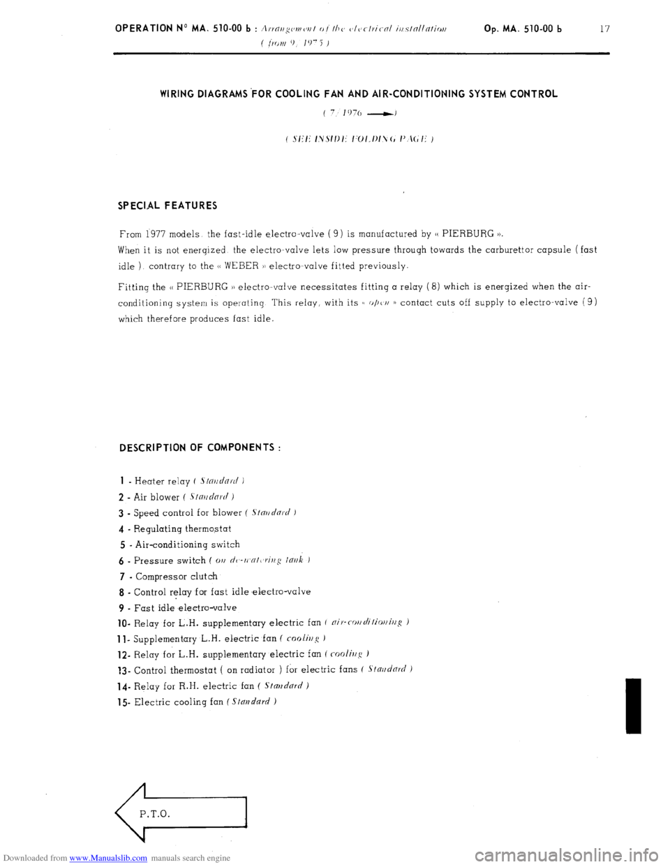
Downloaded from www.Manualslib.com manuals search engine Op. MA. 510-00 b 17 WIRING DIAGRAMS’FOR COOLING FAN AND AIR-CONDITIONING SYSTEM CONTROL
SPECIAL FEATURES
From 1977 models the fast-idle electro-valve ( 9) is manufactured by 1, PIERBURG 1).
When it is not enerqized the electro-valve lets low pressure through towards the carburettor capsule (fast
idle ) contrary to the (1 WEBER )) electromvalve fitted previously.
Fitting the N PIERBURG )) electro-valve necessitates fitting a relay (8) which is enerqized when the air-
conditioning system is operating This relay, with its c( o/)t/i 1) contact cuts off supply to electro-valve (9)
which therefore produces fast idle. DESCRIPTION OF COMPONENTS :
1
- Heater relay ( .s/o~/~/Q~c/ )
2 - Air blower ( .S~n~~dnr(i i
3 - Speed control for blower ( S/nr/clnrt/ J
4 - Regulating thermostat
5 - Air-conditioning switch 6
- Pressure switch ( 01, dc,-rt,cr/t,rit,,q lnr~k ) 7
- Compressor clutch
8 - Control relay for fast idle melectro-valve
9 - Fast idle electro-valve lo-
Relay for L.H. supplementary electric fan f nip-cor/rli/ior/illS ) 1
I- Supplementary L.H. electric fan ( foolir2~~ ) 12-
Relay for L.H. supplementary electric fan ( cooli~/g ) ?3-
Control thermostat ( on radiator ) for electric fans ( Stnr~d& )
14- Relay for R.H. electric fan ( Stmzdnrrl )
15 Electric cooling fan ( Stal?dn~/ )
Page 339 of 394
Downloaded from www.Manualslib.com manuals search engine 20 OPERATION No MA. 510-00 b : Ivstallatiov oj the c,lcctriral iv~stallatiov
( [KM 9 / I 07 5 )
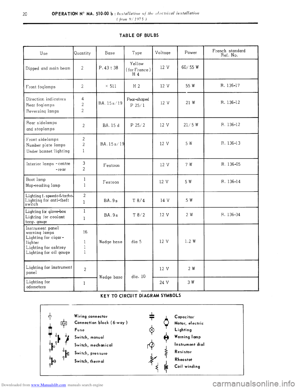
TABLE OF BULBS
juantity Type French standard
Ref. No. Power
60/ 55 W Voltage
12 v Base
P. 43 t 38 Use
lipped and main beam
Front foqlamps
Direction indicators
Rear foqlamps
Reversinq lamps
Rear sidelamps
and stoplamps
Front sidelamps
Number plate lamps
Under bonnet ‘lighting
Interior lamps -centre
-rear
Boot lamp
Map-reading lamp
&iqhtinq f . speed0 & tachl
~~$;~q for anti-theft
diqhtinq for glove-box
-iqhtinq for coolant
.emp. gauge
[nstrument panel
warning lamps
Lighting for cigar -
lighter
Lighting for ashtray
Lighting for oil gauge
Lighting for instrumen
panel
Lighting for
odometers Yellow
for France )
H4 2
x 51 H2 12 V 55 w
--
21 w R. 136-17
4
2
2 Pear-shaped
P 25/ 1 R. 136-12
BA. 12 v
12 v 21,‘5 W R. 136-12
2 BA. 15 d P 25/2
R. 136-13
BA. 15s/ 5w
7w
5w
5w 12 v
12 v
12 v
14 v 3
2 R. 136-05
Festoon
Festoon
BA.9s
T 874 R. 136-14 1
1
2
1
T 8/2 12 v 2w R. 136-34
BA. 9,s
16
Wedge base dia 5 12 v 1.2 w
Wedge base dia. 10 2w 12 v
24 V 3w
1 --
KEY TO CIRCUIT DIAGRAM SYMBOLS +
Wiring qonnector
0 Capacitor.
4 6V Connection block (S-way )
Motor, electric
Fuse Lighting
b b
Switch, manual Warning I amp
A P
P u
Switch, mechanical Instrument .dial
P A
)# Switch, pressure Resistor
b P
IQ Switch, thermal Rheostat
?
Coil winding
Page 353 of 394
Downloaded from www.Manualslib.com manuals search engine OPERATION N9 MA. 530.0 : Cbcc-king thv c)lcctrical com&r~cr~ts Op. MA. 530.0 1
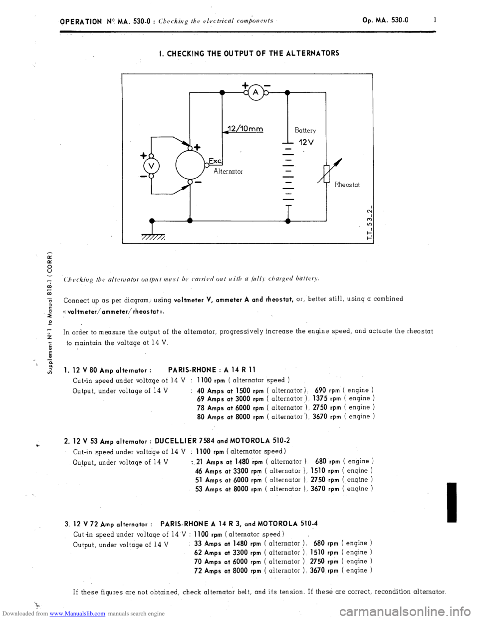
I. CHECKING THE OUTPUT OF THE ALTERNATORS
7
co
co
5 or, better still, using a combined
z Connect up as per diagram; using
voltmeter V, ammeter A and rheostat,
,iiJ (( voItmeter/ammeter/rheostat~~.
2
-
2 In order to measure the output of the alternator, progressively increase the engine speed, and actuate the rheostat
5 to maintain the voltage at 14 V.
E
-c
9
*
1. 12 V 80 Amp alternator : PARIS-RHONE : A 14 R 11
Cut-in speed under voltage of 14 V : 1100 rpm ( alternator speed )
Output, under voltage of 14 V :
40 Amps at 1500 rpm ( alternator j. 690 rpm ( engine )
69 Amps at 3000 rpm ( alternator ), 1375 rpm ( engine )
78 Amps at 6000 rpm ( alternator ). 2750 rpm ( engine )
80 Amps at 8000 rpm ( alternator ‘), 3670 rpm ( engine )
F 2. 12 V 53 Amp alternator : DUCELLIER 7584 and MOTOROLA 510-2 Cut-in speed under voltage of 14 V : 1100 rpm ( alternator speed)
Output, under voltage of 14 V
z.21 Amps at 1480 rpm ( alternator 1 680 rpm ( engine )
46 Amps at 3300 rpm ( alternator ): 1510 rpm ( engine )
51 Amps at 6000 rpk ( alternator ) 2750 rpm (engine )
53 Amps at 8000 rpm ( alternator ). 3670 rpm ( engine )
3. 12 V 72 Amp alternator : PARIS-RHONE A 14 R 3, and MOTOROLA 510-4
Cut-in speed under voltage of 14 V : 1100 rpm ( alternator speed)
Output, under voltage of 14 V : 33
Amps at 1480 rpm ( alternator ). 680 rpm ( engine )
62 Amps at 3300 rpm ( alternator 1 1510 rpm ( engine )
70 Amps at 6000 rpm
( alternator ) 2750 rpm ( engine )
72 Amps at 8000 rpm ( alternator 1. 3670 rpm ( engine )
If these figures are not obtained, check alternator belt, and its tension. If these are correct, recondition alternator
Page 354 of 394
Downloaded from www.Manualslib.com manuals search engine Il. CHECKING THE REGULATED TENSION OF THE REGULATORS
CHARACTERISTICS
- Two-stage voltage regulator : Ref : DUCELLIER 8379 A, PARIS-RHONE AYC 2114 and AYC 2117.
SEV-MARCHAL F. 14 V 72717102
These voltage regulators determine the intensity of the current in the alternator inductor in order to maintain a
constant regulated voltage at the battery terminals.
, CHECKING THE REGULATED VOLTAGE
(.‘hcckitlg ti7c rc~~~~~l~tc~cl u~IIcl,~c~ mris t 170 rnrric,rl out u,ith a lrilly darg~~rl hnttcry.
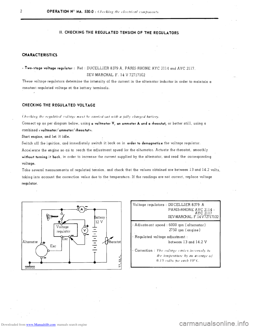
Connect up as per diagram below, using a voltmeter V, an ammeter A and a rheostat, or better still, using a
combined
o voltmeter/ammeter/ rheostat )).
Start engine, and let it idle.
Switch off the ignition, and immediately switch it back on in
order to demagnetize the voltage regulator.
Accelerate the engine so as to reach the adjustment speed for the alternator. Actuate the rheostat, smoothly
without turning it back, in order to increase the current supplied by the alternator, and read the corresponding
voltage.
Take several measurements of regulated tension, and check that the values obtained are between 13 and 14.2 volts,
taking into account the correction value due to the temperature. If the readings are not correct, replace voltage
regulator.
Exe Voltage regulators : DUCELLIER 8379 A
PARIS-RHONE ;;E ;;;; -
SEV-MARCHAL F.14 V72717102
- Adjustment speed : 6000 rpm (alternator)
2750 rpm (engine)
- R egulated voltage adjustment :
between 13 and 14.2 V