gearbox Citroen CX 1983 1.G Service Manual
[x] Cancel search | Manufacturer: CITROEN, Model Year: 1983, Model line: CX, Model: Citroen CX 1983 1.GPages: 394
Page 362 of 394

Downloaded from www.Manualslib.com manuals search engine II. OPERATING PRINCIPLE
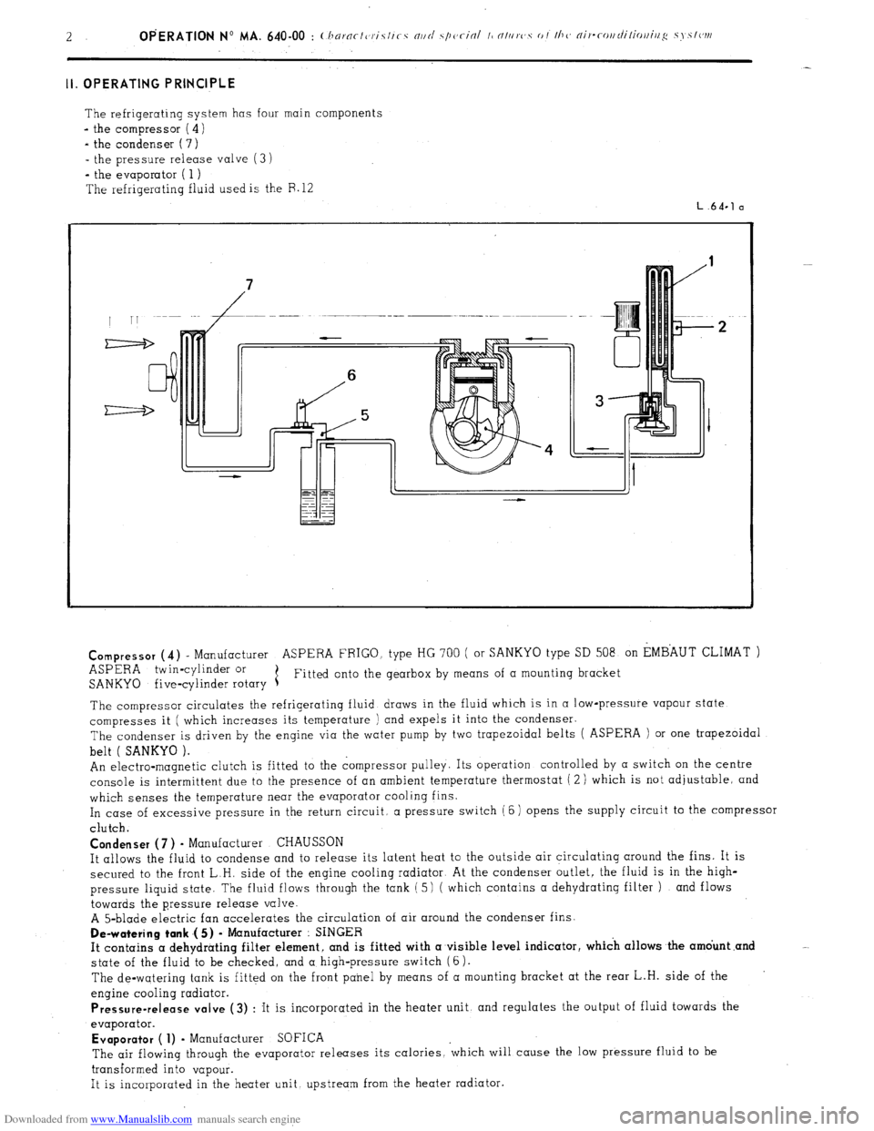
The refrigerating system has four main components
- the compressor ( 4)
- the condenser ( 7)
- the pressure release valve (3 i
*
the evaporator ( 1 )
The refrigerating fluid used is the F. 12
L.64.1 a
Compressor
(4) - Manufacturer ASPERA FRIGO. type HG 700 ( or SANKYO type SD 508 on EMBAUT CLIMAT )
ASPERA twin-cylinder or
SANKYO five-cylinder rotary 1 Fitted onto the gearbox by means of a mounting bracket
The compressor circulates the refrigerating fluid draws in the fluid which is in a low-pressure vapour state
compresses it ( which increases its temperature ) and expels it into the condenser.
The condenser is driven by the engine via the water pump by two trapezoidal belts ( ASPERA ) or one trapezoidal
belt ( SANKYO ).
An electro-magnetic clutch is fitted to the compressor pulley. Its operation controlled by a switch on the centre
console is intermittent due to the presence of an ambient temperature thermostat ( 2 ) which is not adjustable, and
which senses the temperature near the evaporator cooling fins.
In case of excessive pressure in the return circuit, a pressure switch (6) opens the supply circuit to the compressor
clutch.
Condenser (7 ) - Manufacturer CHAUSSON
It allows the fluid to condense and to release its latent heat to the outside air circulating around the fins. It is
secured to the front L.H. side of the engine cooling radiator At the condenser outlet, the fluid is in the high-
pressure liquid state. The fluid flows through the tank ( 5) ( which contains a dehydrating filter ) and flows
towards the pressure release valve.
A 5-blade electric fan accelerates the circulation of air around the condenser fins.
De-watering tank .( 5) - Manufacturer : SINGER
It contains a dehydrating filter element, and is fitted with a visible level indicator, which allows the amdunt .and
state of the fluid to be checked, and a high-pressure switch (6).
The de-watering tank is fitted on the front panel by means of a mounting bracket at the rear L.H. side of the
engine cooling radiator.
Pressure-release valve (3) : It is incorporated in the heater unit, and regulates the output of fluid towards the
evaporator.
Evaporator ( 1) - Manufacturer SOFICA
The air flowing through the evaporator releases its calories, ‘which will cause the low pressure fluid to be
transformed into vapour.
It is incorporated in the heater unit upstream from the heater radiator.
Page 365 of 394

Downloaded from www.Manualslib.com manuals search engine OPERATION No MA. 640-00 : (:hnrnc-/eris/ics nrtd s.pcc-in/ ~bntttrcs of I/T<< nir- Op. ihA. 640-00 5
c-ottdiliottittg systc~ttt
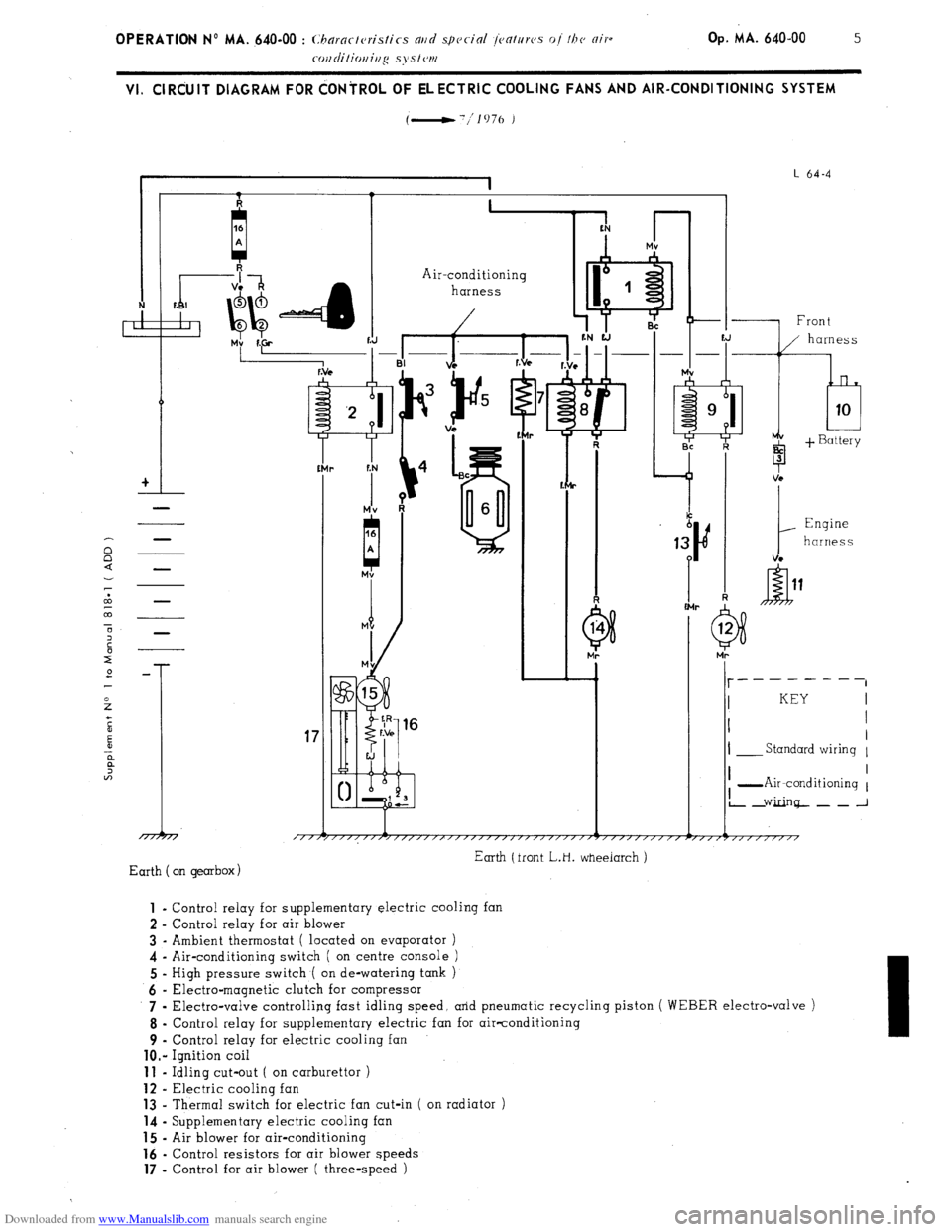
VI. ClRdUlT DIAGRAM FOR dONiROL OF ELECTRIC COOLING FANS AND AIR-CONDITIONING SYSTEM
(-'/lo76 )
I
I L 64-4
I 1. I
+I
-
Air-conditioning
harness
r
-I% ii.+
f:N
r
Mv
A
-1 Front
b 3
1
Engine
harness
VC -
I- __------
I KEY
I I
I
I- Standard wiring 1
17
/TTj I I
I -Air-conditioning 1
L2Ginq--~_J
Earth (front L.H. wheeiarch )
Earth on gearbox) 1
- Control relay for supplementary electric cooling fan
2 - Control relay for air blower
3 - Ambient thermostat ( located on evaporator )
4 - Air-conditioning switch ( on centre console )
5 - High pressure switch ( on de-watering tank )
6 - Electra-magnetic clutch for compressor
7 .
Electra-valve controlling fast idling speed, arid pneumatic recycling piston ( WEBER electro-valve )
8 - Control relay for supplementary electric fan for air-conditioning
9 - Control relay for electric cooling fan
lo.- Ignition coil 11
- Idling cut-out ( on carburettor ) 12
- Electric cooling fan 13
- Thermal switch for electric fan cut-in ( on radiator ) 14
- Supplementary electric cooling fan 15
- Air blower for air-conditioning 16
- Control resistors for air blower speeds 17
- Control for air blower ( three-speed )