coolant level Citroen CX 1983 1.G Workshop Manual
[x] Cancel search | Manufacturer: CITROEN, Model Year: 1983, Model line: CX, Model: Citroen CX 1983 1.GPages: 394
Page 170 of 394

Downloaded from www.Manualslib.com manuals search engine CHARACTERISTICS
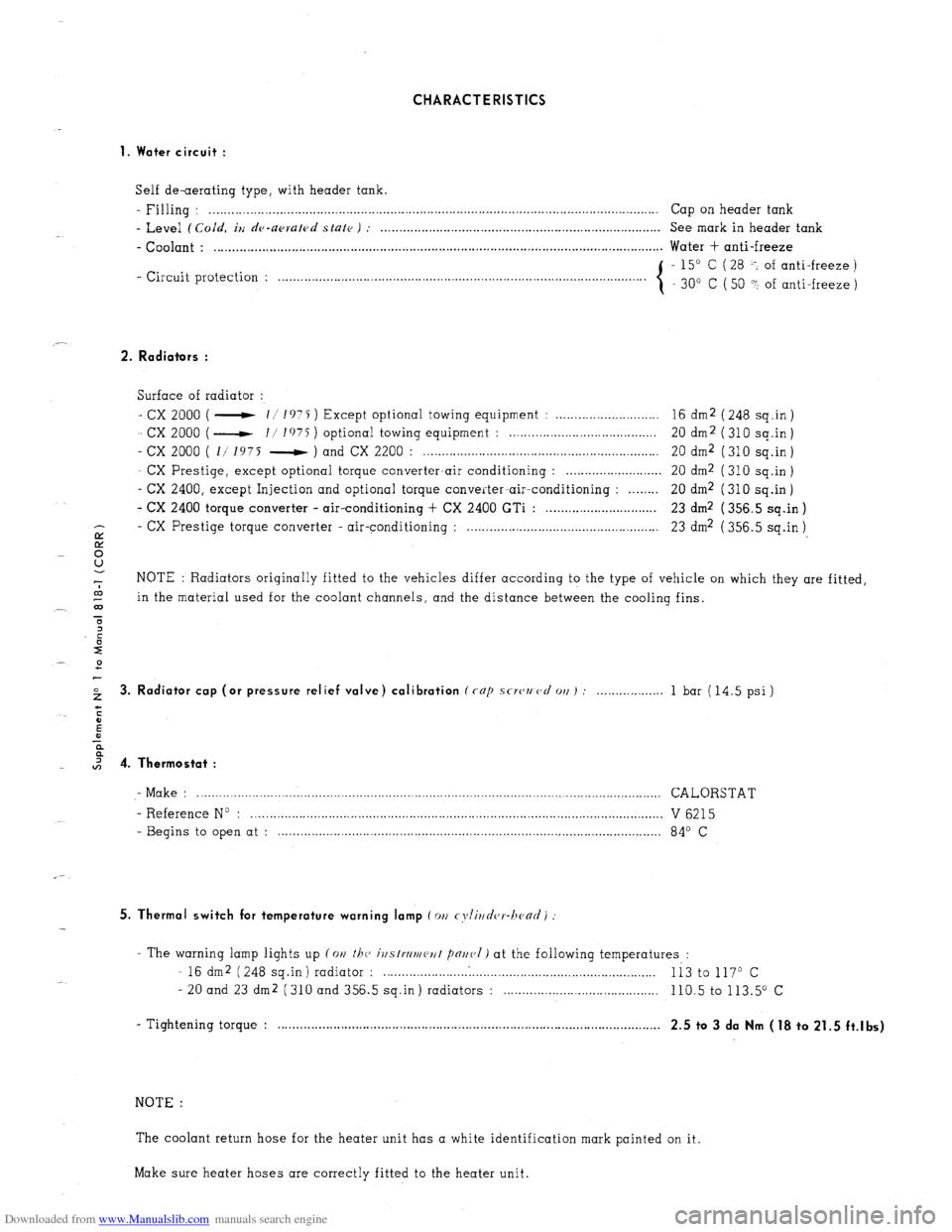
1. Water circuit :
Self de-aerating type, with header tank.
- Filling : . . . . . . . .._................................................................................................................ Cap on header tank
- Level (Cold, iu de-upruled state ) : . . . . . . . . . . . . . . . . . . . . . . . . . . . . . . . . . . . . . . . . . . . . . . . . . . . . . . . . . . . . . . . . . . . . . . . . . . . . See mark in header tank
- Coolant : . . . . . . . . . . . . . . . . . . . . . . . . . . . . . . . . . . . . . . . . . . . . . . . . . . . . . . . . . . . . . . . . . . . . . . . . . . . . . . . . . . . . . . . . . . . . . . . . . . . . . . . . . . . . . . . . . . . . . . . . .. Water + anti-freeze
- Circuit protection : - 15” C ( 28 -: of anti-freeze )
. . . . . . . . . . . . . . . . . . . . .
30” C ( 50 ? of anti-freeze )
2. Radiators :
Surface of radiator :
- cx 2000 ( - 11 1975 ) Except optional towing equipment : . . . . . . . . . . . . . . . . . . . . . . . . . . . . 16 dm2 ( 248 sq.in )
- cx 2000 ( - I/ I’)75 ) optional towing equipment : . . . . . . . . . . . . . . . . . . . . . . . . . . . . . . . . . . . . . . 20 dm2 (310 sq.in)
- cx 2000 ( 1/ 1975 - ) and CX 2200 : . . . . . . . . . . . . . . . . . . . . . . . . . . . . . . . . . . . . . . . . . . . . . . . . . . . . . . . . . . . . . . . . 20 dm2 ( 310 sq.in )
- CX Prestige, except optional torque converter-air conditioning : . . . . . . . . . . . . . . . . . . . . . . . . . . 20 dm2 ( 310 sq.in )
- CX 2400, except Injection and optional torque converter-air-conditioning : . . . . . . . . 20 dm2 (310 sq.in)
- CX 2400 torque converter - air-conditioning + CX 2400 GTi : . . . . . . . . . . . . . . . . . . . . . . . . . . . . . . 23 dm2 ( 356.5 sq.in )
- CX
E Prestige torque converter - air-conditioning : . . . . . . . . . . . . . . . . . . . . . . . . . . . . . . . . . . . . . . . . . . . . . . . . . . . . 23 dm2 ( 356.5 sq.in )
8
-7 NOTE : Radiators originally fitted to the vehicles differ according to the type of vehicle on which they are fitted,
co
_- 03 in the material used for the coolant channels, and the distance between the cooling fins.
T
2 3. Radiator cap (or pressure relief valve) calibration (rap scwzmcl 011) : . . . 1 bar (14.5 psi)
I 4. Thermostat :
- Make : .............................................................................................................................. CALORSTAT
- Reference No : ................................................................................................................ V 6215
- Begins to open at : ........................................................................................................ 84’ C
5. Thermal switch for temperature warning lamp (011 cyli~~d(,r-hc~ad)
- The warning lamp lights up (on the, ivstrrlmeut pnr~(,I) at the following temperatures :
- 16 dm2 (248 sq.in) radiator : . . . . . . . . . . . . .
Ii3 to 117O c
- 20 and 23 dm2 (310 and 356.5 sq.in) radiators : . . . . 110.5 to 113.5” c
- Tightening torque : . . . . . . . . . . . . . . . . . . . . . . . . . . . . . . . . . . . . . . . . . . . . . . . . . . . . . . . . . . . . . . . . . . . . . . . . . . . . . . . . . . . , . . . . . . . . . . . . . . . . . . . .
2.5 to 3 da Nm (18 to 21.5 ft.lbs)
NOTE :
The coolant return hose for the heater unit has a white identification mark painted on it.
Make sure heater hoses are correctly fitted to the heater unit.
Page 179 of 394

Downloaded from www.Manualslib.com manuals search engine 2 OPERATION No MA. 230-O : II .h’ 0, fug Ol, I/7‘, rodir,p sys/w1.
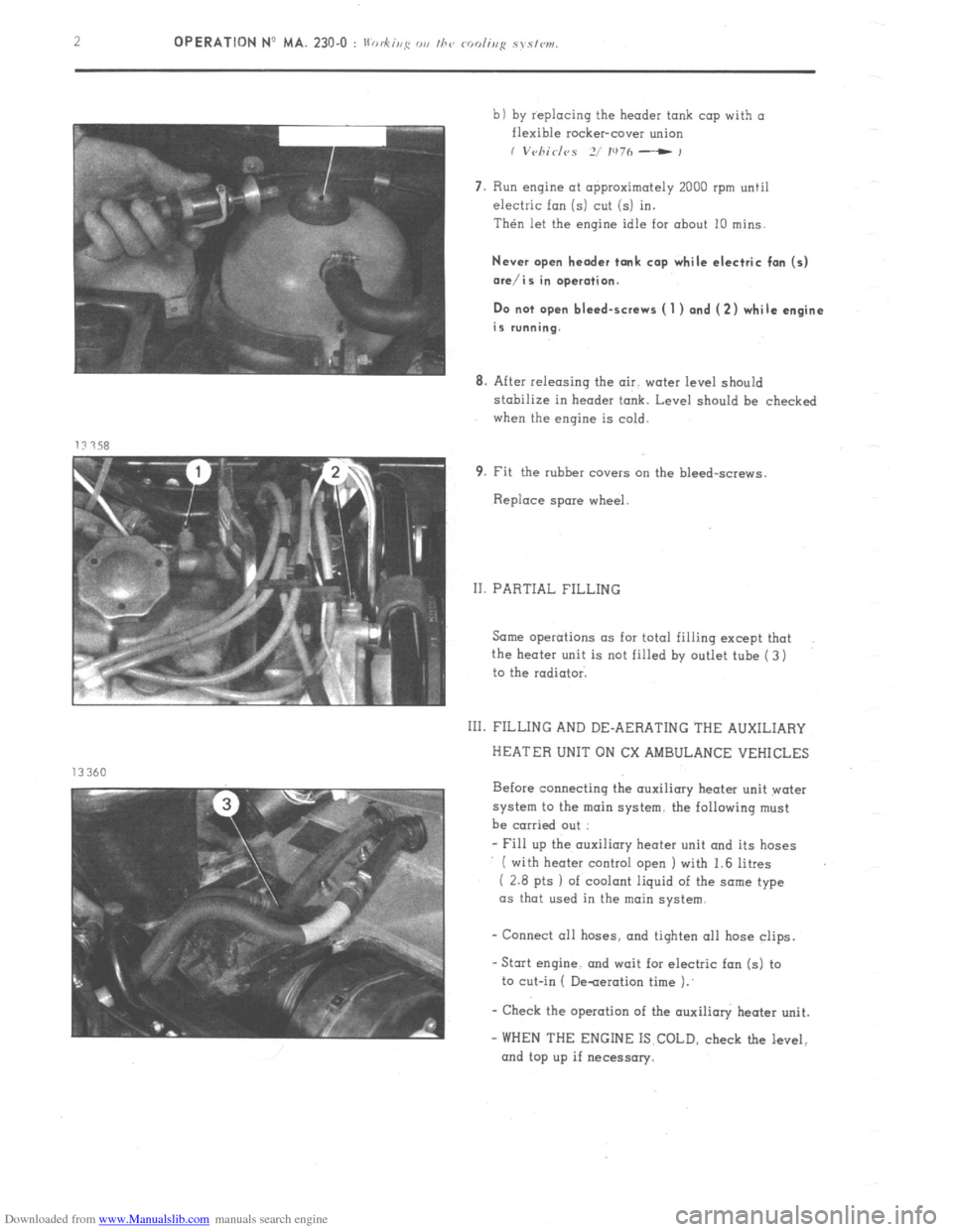
b) by replacing the header tank cap with a
flexible rocker-cover union
I V~~/7id<~S 2/ IU7h - ,
7. Run engine at approximately 2000 rpm until
electric fan (5) cut (5) in.
Then let the engine idle for about 10 mins.
Never open header tank cap while electric fan (5)
ore/is in operation.
Do not open bleed-screws ( 1 ) and (2) while engine
is running.
8. After releasing the air. water level should
stabilize in header tank. Level should be checked
when the engine is cold.
9. Fit the rubber covers cm the bleed-screws.
Replace spare wheel.
II. PARTIAL FILLING
Same operations as for total filling except that
the heater unit is not filled by outlet tube ( 3)
to the radiator.
111. FILLING AND DE-AERATING THE AUXILIARY
HEATER UNIT ON CX AMBULANCE VEHICLES
Before connecting the auxiliary heater unit water
system to the main system. the following must
be carried out :
- Fill up the auxiliary heater unit and its hoses
( with heater control open I with 1.6 litres
( 2.8 pts 1 of coolant liquid of the some type
as that used in the main
system.
- Connect all hoses. and tiqhten 011 hose clips.
-Stat engine. and wait for electric fan (5) to
to cut-in ( De-aeration time 1.’
- Check the operation of the auxilioly heater unit.
- WHEN THE ENGINE IS COLD, check the level,
and top up if necessary.
Page 340 of 394

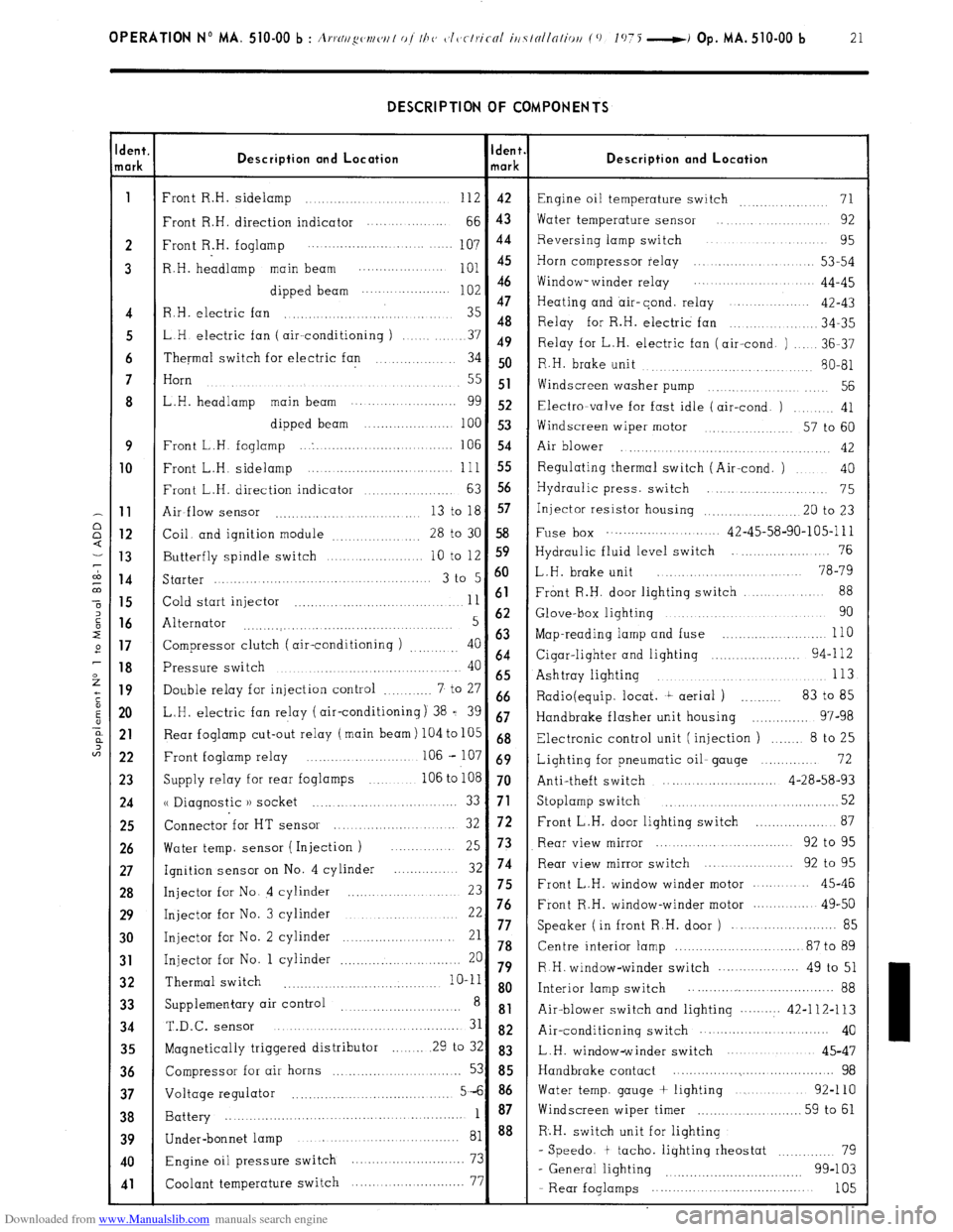
Downloaded from www.Manualslib.com manuals search engine OPERATION No MA. 510-00 b : A,.,.N//~w~/w/ of I/J<, c~l~~clriccrl iti7tollnliou (0 1075 -i Op. MA. 510-00 b 21 DESCRIPTION OF COMPONENTS
dent.
lark Description and Location Ident.
mark Description and Location
1
Front R.H. sidelamp ............................ 112 42
Engine oil temperature switch 71 ...............
Front R.H. direction indicator .... ... .........
66 43 Water temperature sensor .... .............. 92
2 Front R.H. foglamp 107 44 Reversing lamp switch ................... 95
..................... ....... ....
3 R.H. headlamp main beam
;:: :: Horn compressor relay ..................... 53-54
............... ....
dipped beam Window- winder relay .................. 44-45
......................
47
Heating and air-cond. relay ...............
4 R.H. electric fan ............................... 35 42-43
48
.............. 34-35
5 LH electric fan ( air--conditioning ) Relay for R.H. electric fan
........ 37 49
Relay for L.H. electric fan (air-cond. ) ..... 36-37
6 Thermal switch for electric fan .............. 34 50
R.H. brake unit
........... 80-81
......... ............
7 Horn
....................................
.......... ..... 55 51
Widscreen washer pump .............. .... 56
8 L.H. headlamp main beam ........... ..........
gg 52 Electra-valve for fast idle (air-cond. ) ......... 41
dipped beam ......................
100 53
Windscreen wiper motor ............. 57 to 60
9 Front L.H. foglamp ... . ...............................
106 54
Air blower ..............
........... ..... ........... 42 10
Front L.H. sidelamp ......................... ... ... .. 111 55 Regulating thermal switch (Air-cond. ) .... 40
Front L.H. direction indicator
63 56 ................... Hydraulic press. switch .......................
75 11
Air-flow sensor 13 to 18 57
........................... ... Injector resistor housing .................... .20 to 23 12
Coil. and ignition module
28 to 30 58 Fuse box ............................ 42-45-58-90-105-l 11
................. 13
Butterfly spindle switch 10 to 12 S9 Hydraulic fluid level switch ...................... 76
.................... 14
Starter 3 t0 5 6o L.H. brake unit ........................ 78-79
..........................................
88 15
Cold start injector 11 61 Front R.H. door lighting switch ....... ....
.................................. 16
Alternator 5 62 Glove-box lighting ................................ 90
...........
....... ..................... ....... 17
Compressor clutch ( air-conditioning ) 40 63 Map-reading lamp and fuse ............... ..... ... 110
.........
64 18
Pressure switch 40 Cigar-lighter and lighting ...................... 94-l 12
........................................
65 Ashtray lighting 113 ..................................... 19
Double relay for injection control 7 to 27 ............ 66
Radio(equip. locat. t aerial ) .......... 83 to 85
20 L.H. electric fan relay (air-conditioning) 38 = 39 67
Handbrake flasher unit housing .............. 97-98 21
Rear foglamp cut-out relay (main beam) 104 to 105 68
Electronic control unit (injection ) ....... 8 to 25
22 Front foglamp relay ....................... .. 106 - 107 69
Lighting for pneumatic oil- gauge .............. 72
23
Supply relay for rear foglamps ............ 106 to 108 70
Anti-theft switch ............................ 4-28-58-93 24
u Diagnostic )) socket 52 ......... ....... ... ..... ........ 33 71 Stoplamp switch ...................................... 25
Connector for HT sensor 72 ................... 87
....................... 32 Front L.H. door lighting switch 26
Water temp. sensor ( Injection ) Rear view mirror ............................ 92 to 95
... 25 73
27
Ignition sensor on No. 4 cylinder 32 74 Rear view mirror switch ................... 92 to 95
............. 28
Injector for No. 4 cylinder ...................... 23 75 Front L.H. window winder motor .......... 45-46 29
Injector for No. 3 cylinder 22 76 Front R.H. window-winder motor .............. 49-50
...........................
......................... 85 30
Injector for No. 2 cylinder 21 77 Speaker ( in front R.H. door )
......................... 78 Centre interior lamp ............................... 87 to 89 31 Injector for No. 1 cylinder 20 ............................. 79 R H. window-winder switch .................... 49 to 51 32 Thermal switch
........... .......................... 10-11 8 o
Interior lamp switch .................... ................ 88
33 Supplementary air control ............................
8 81
Air-blower switch and lighting .......... 42-112-113 34 T.&c.
SenSOr ........................................... 31 82 Air-conditioning switch ............... ............ 40
35
Magnetically triggered distributor ........ 29 to 32 83
L.H. window-winder switch .....................
45-47 36
Compressor for air horns ............. ..... ......... 53 85 Handbrake contact ......................................... 98 37
Voltage regulator 5-6 86 Water temp. gauge + lighting ..................
92-110
....................................... 38
Battery 1 87 Windscreen wiper timer
.......................... 59 to 61
....................................................... 39
40
41
Under-bonnet lamp ........................................ 81 88 R.H. switch unit for lighting
Engine oil pressure switch 73 - Speedo. t tacho. lighting rheostat ............ 79
............................
99-103
Coolant temperature switch 77
- General lighting ................................
....... ....................
- Rear foglamps ..................................... 105