key Citroen CX 1983 1.G Workshop Manual
[x] Cancel search | Manufacturer: CITROEN, Model Year: 1983, Model line: CX, Model: Citroen CX 1983 1.GPages: 394
Page 87 of 394
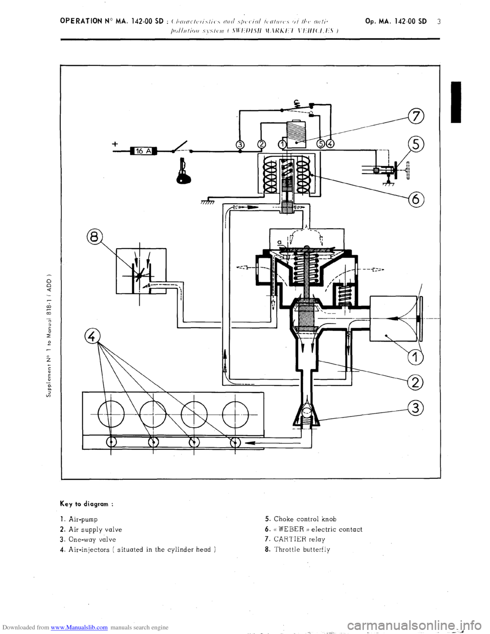
Downloaded from www.Manualslib.com manuals search engine Key to diagram :
1.
Air-pump 5. Choke control knob
2. Air supply valve 6. (( WEBER )) electric contact
3. One-way valve 7. CARTIER relay
4. Air-injectors ( situated in the cylinder head ) 8. Throttle butterfly
Page 189 of 394
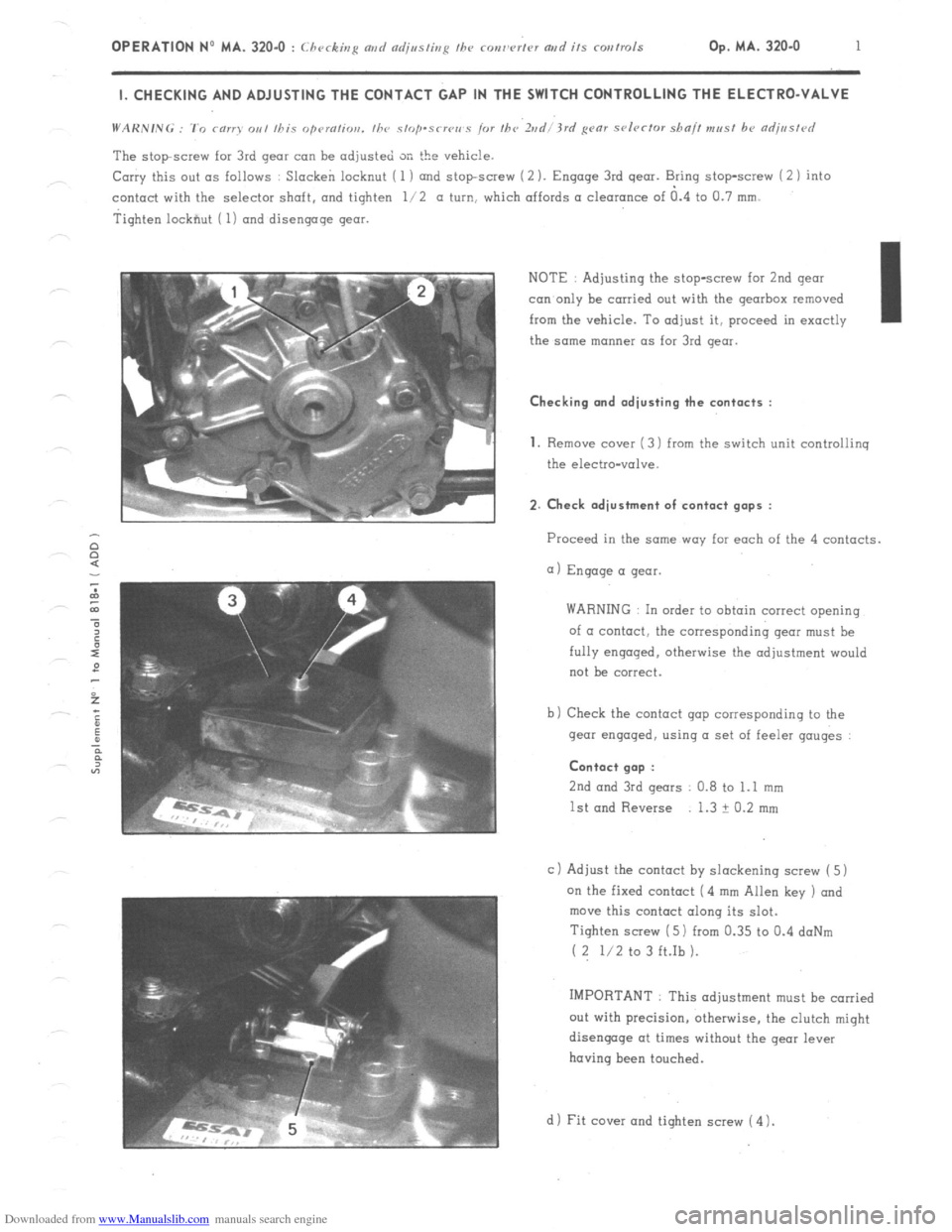
Downloaded from www.Manualslib.com manuals search engine OPERATION No MA. 320-O : Checking md czdjssting fhe ronw’rtcv artd its corrtrols Op. MA. 320.0 1 I. CHECKING AND ADJUSTING THE CONTACT GAP IN THE SWITCH CONTROLLING THE ELECTRO-VALVE
The stopscrew for 3rd gear can be adjusted SK the vehicle.
Carry this out as follows : Slacken locknut ( 1 ) and stopscrew (2 ). Engage 3rd gear. Bring stop-screw i 2 1 into
contact with the selector shaft. and tighten l/2 a turn, which affords a clearance of a.4 to Cl.7 mm.
Tighten lockfiut ( 1) and disengage gear.
NOTE : Adjusting the stop-screw for 2nd gear
con only be carried out with the gearbox removed
from the vehicle. To adjust it, proceed in exactly I
the same manner as for 3rd gear. Checking and adjusting the contacts :
1.
Remove cover ( 3) from the switch unit controliinq
the electro-valve. 2. Check adjustment of contact gaps :
Proceed in the same way far each of the 4 contacts.
a) Engage a gear.
WARNING In order to obtain correct opening
of a contact, the corresponding gear must be
fully engaged. otherwise the adjustment would
not be correct.
b) Check the contact gap corresponding to the
gear engaged, using a set of feeler gauges : Contact gap :
2nd
and 3rd gears 0.8 to 1.1 mm
1st and Reverse 1.3 ? 0.2 mm
c 1 Adjust the contact by slackening screw ( 5)
on the fixed contact (4 mm Allen key ) and
move this contact along its slot.
Tighten screw ( 5) from 0.35 to 0.4 doNm
( 2 l/2 to 3 ft.Ib ).
IMPORTANT : This adjustment must be carried
out with precision, otherwise, the clutch might
disengage at times without the gear lever
having been touched.
d 1 Fit cover and tighten screw ( 4 1.
Page 293 of 394
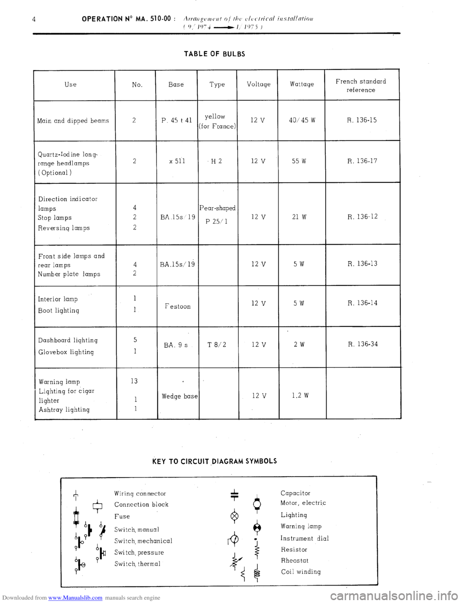
Downloaded from www.Manualslib.com manuals search engine TABLE OF BULBS
Use No. Base
Type Voltage Wattage French standard
reference
ain and dipped beams 2 P. 45 t 41 yellow 12 v 40145 w R. 136-15
(for France)
Quartz-Iodine long-
range headlamps
( Optional ) 2 x 511 -H2 12
v 55 w R. 136-17
Direction indicator
lamps
Stop lamps
Reversing lamps Pear-shaped
BA.15s 19
P 25/l 12 v 21 w R. 136-12
Front side lamps and
rear lamps
Number plate lamps
Interior lamp
Boot lighting BA.lSs/ 19
Festoon 12 v 5w R. 136-13 12
v 5w R. 136-14
Dashboard lighting 5
BA. 9 s T 8/2 12 v 2w R. 136-34
Glovebox lighting 1
Warning lamp
Lighting for cigar
lighter
Ashtray lighting 13
1
1 Wedge base 12 v 1.2 w KEY TO CIRCUIT ,DIAGRAM SYMBOLS
Wiring connector
Connection block
Fuse
Switch, manual
Switch, mechanica
Switch, pressure
Switch, thermal 1 Capacitor
Motor, electric
0 Lighting
$ Warning lamp
4 a Instrument dial
Resistor
I
Rheostat
Coil winding
Page 301 of 394
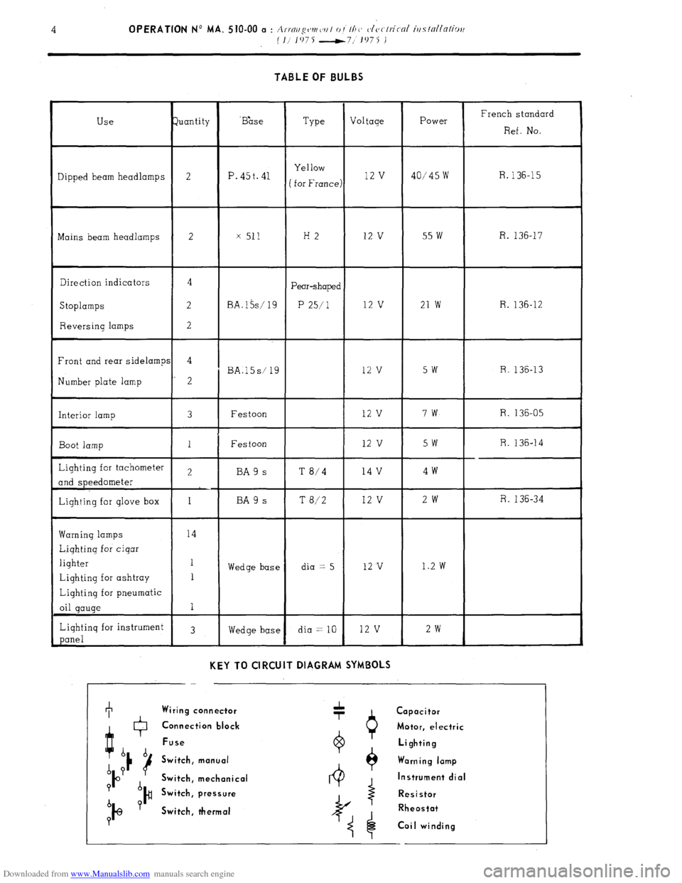
Downloaded from www.Manualslib.com manuals search engine TABLE OF BULBS
Use Juantity ‘B&e
Type Voltage Power French standard
Ref. No.
Yellow
Dipped beam headlamps 2 P. 45t. 41 R.
( for France) 12 v 40/45 w 136-15
Mains beam headlamps 2 x 511 H2 12 v 55 w R. 136-17
Direction indicators 4
Pear-shaped
Stoplamps 2 BA.l5s/ 19 P 25/l 12 v 21 w R. 136-12
Reversing lamps 2
Front and rear sidelamps 4
BA.l5s/ 19 12 v 5w R. 136-13
Number plate lamp 2
Interior lamp 3 Festoon 12 v 7w R. 136-05
Boot lamp 1 Festoon 12 v 5w R. 136-14
Lighting for tachometer 2 BA 9 s T
8/4 14 v 4w
and speedometer
Lighting for glove box 1 BA 9 s T 8/2 12 v 2w R. 136-34
Warning lamps 14
Lighting for cigar
lighter 1
Wedge base dia == 5 12 v 1..2 w
Lighting for ashtray 1
Lighting for pneumatic
oil gauge I
Lighting for instrument
3
panel Wedge base dia = 10 12 v 2w
KEY TO CIRCUIT DIAGRAM SYMBOLS
I Wiring connector
Q + Capacitor
0 Connection black Motor, electric
Fuse
b b Lighting
d ? 16 Switch, manual Warning lamp
IO Switch, mechanical Instrument dial
? d
Switch, pressure Resistor
b ?
I@ )#
Switch, thermal Rheostat
P
Coil winding
Page 309 of 394
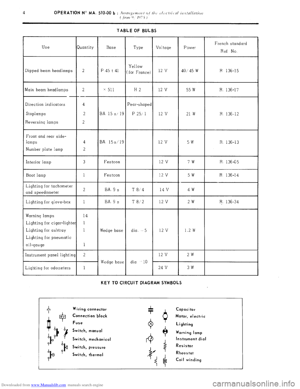
Downloaded from www.Manualslib.com manuals search engine 4 OPERATION No MA. 510-00 b : it ..n < ,I ,/“c’mc’,, I oi Ill<’ ~‘IVfl,.iC NI iilClNllNtiorl
( ~KJI~I l), 107 5 j
TABLE OF BULBS
French standard
Ref No.
R 136-15 Type Voltage Power luantity Use
Dipped beam headlamps
2
Base
P.45 t 41 Yellow
for France) 12 v
40/ 45 w
x 511 H2 12 v 55 w R. 136-17 2
--
4
2
2 Main beam headlamps
Direction indicators
Stoplamps
Reversinq lamps
Front and rear side-
lamps
Number plate lamp ‘ear-shape<
P 25/ 1 3A 1
S/ 9
12 v 21 w R 136-12
3A 15s/ 9
12 v
5w R. 136-13
R. 136-05
I Interior lamp Festoon 12 v 7w
Festoon
12 v 5W R 136-14 Boot lamp
4v 4w BA.9 s
BA 9 s T 8/4
T 8/2 1 12 v 2w R. 136-34
Warning lamps
Lighting for cigar-light
Lighting for ashtray
Lighting for pneumatic
oil-gauge
Instrument panel lighti
Liqhting for odometers
I I dia. -5 12 v 1.2 w
Wedge base
Wedge base dia 10
2 12 v 2w
1 24 V 3w
KEY TO CIRCUIT DIAGRAM SYMBOLS +
Wiring connector
Capacitor
4 0 6V Connection block
Motor, electric
Fuse
6 b Lighting
u Switch, manual
A Y Warning lamp
b Switch, mechanical Instrument dial
? d
)# Switch, pressure Resistor
b Y
IQ Switch, thermal Rheostat
0 Coil winding
Page 317 of 394
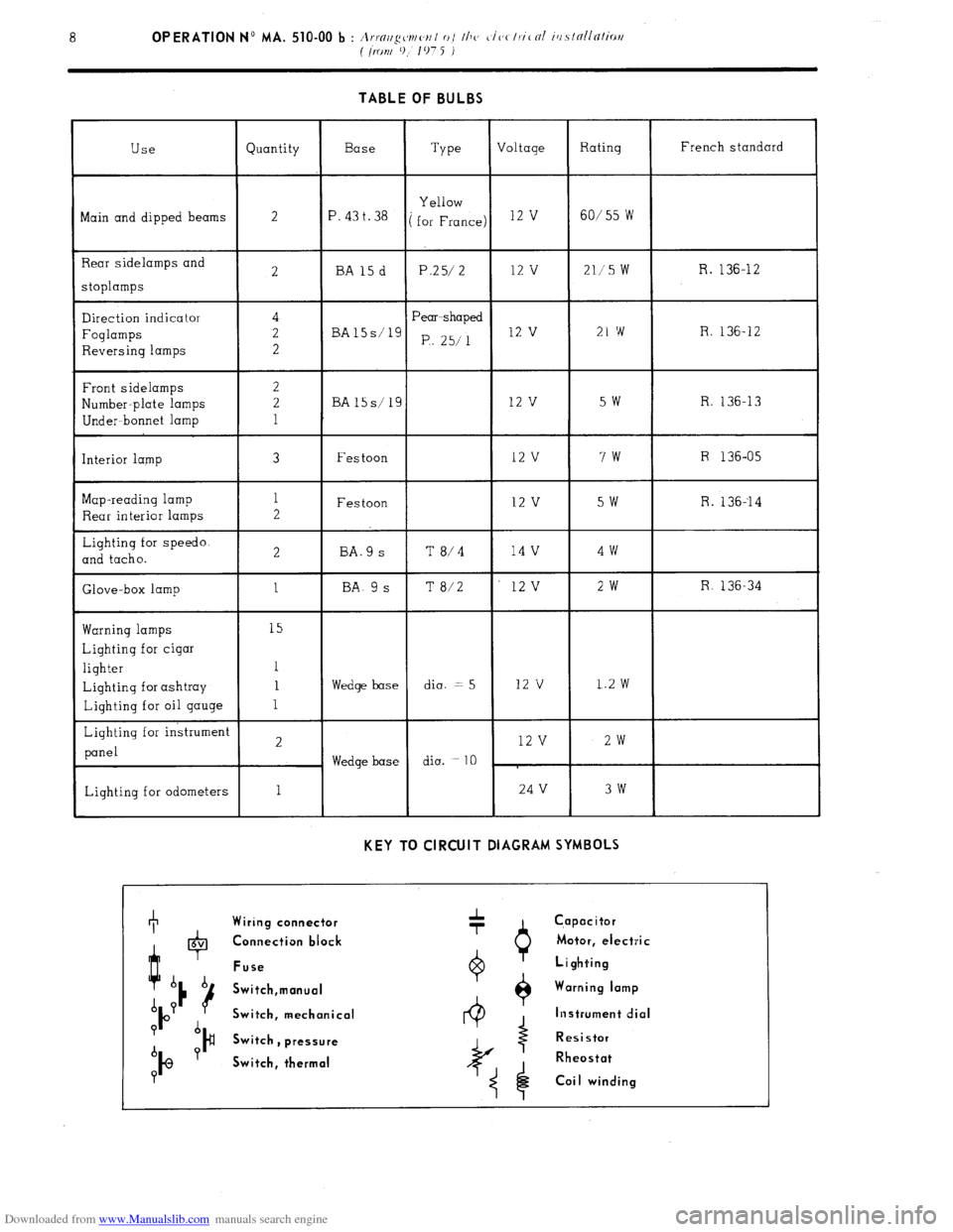
Downloaded from www.Manualslib.com manuals search engine TABLE OF BULBS
Use Quantity Base
Type Voltage Rating French standard
Bain and dipped beams Yellow
2
‘. 43 t. 38 ( for France) l2 ’ 60/55 W
3ear sidelamps and
3tOplamps
2 BA15d P.25/ 2 12 v 211’5 W R. 136-12
Direction indicator
Foglamps
Reversing lamps
Front sidelamps
yumber-plate lamps
Under- bonnet lamp
[nterior lamp
Wap-reading lamp
Rear interior lamps
Lighting for speedo.
2nd tacho.
Slave-box lamp 4
2
2
2
2
1
3
1
2
2
1 Pear-shaped
BA15s’1g
P,. 25/l 12 v 21 w R. 136-12
BA15s/19 12 v 5w R. 136-13
Festoon 12 v 7w R 136-05
Festoon 12 v 5W R. 136--14
BA.9 s T 8/4 14 v 4w
BA. 9 s T 8/2 12v 2w R 136-34
tiarning lamps 15
Lighting for cigar
lighter 1
Lighting for ashtray 1 Wedge base dia. = 5 12 v 1.2 w
Lighting for oil gauge 1
Lighting for instrument
2 12 v 2w
panel
Wedge base diu. =
10
Lighting for odometers 1 24 V 3w
KEY TO CIRCUIT DIAGRAM SYMBOLS +
Wiring connector A
-r C,apacitor
t 0 6V Connection block Motor, electric
Fuse Lighting
b b
16 Switch,manual Warning lamp
A P
P Switch, mechanical Instrument dial
? b
)# Switch
b Y , pressure Resistor
IQ Switch, thermal Rheostat
P
Coi I winding
Page 325 of 394
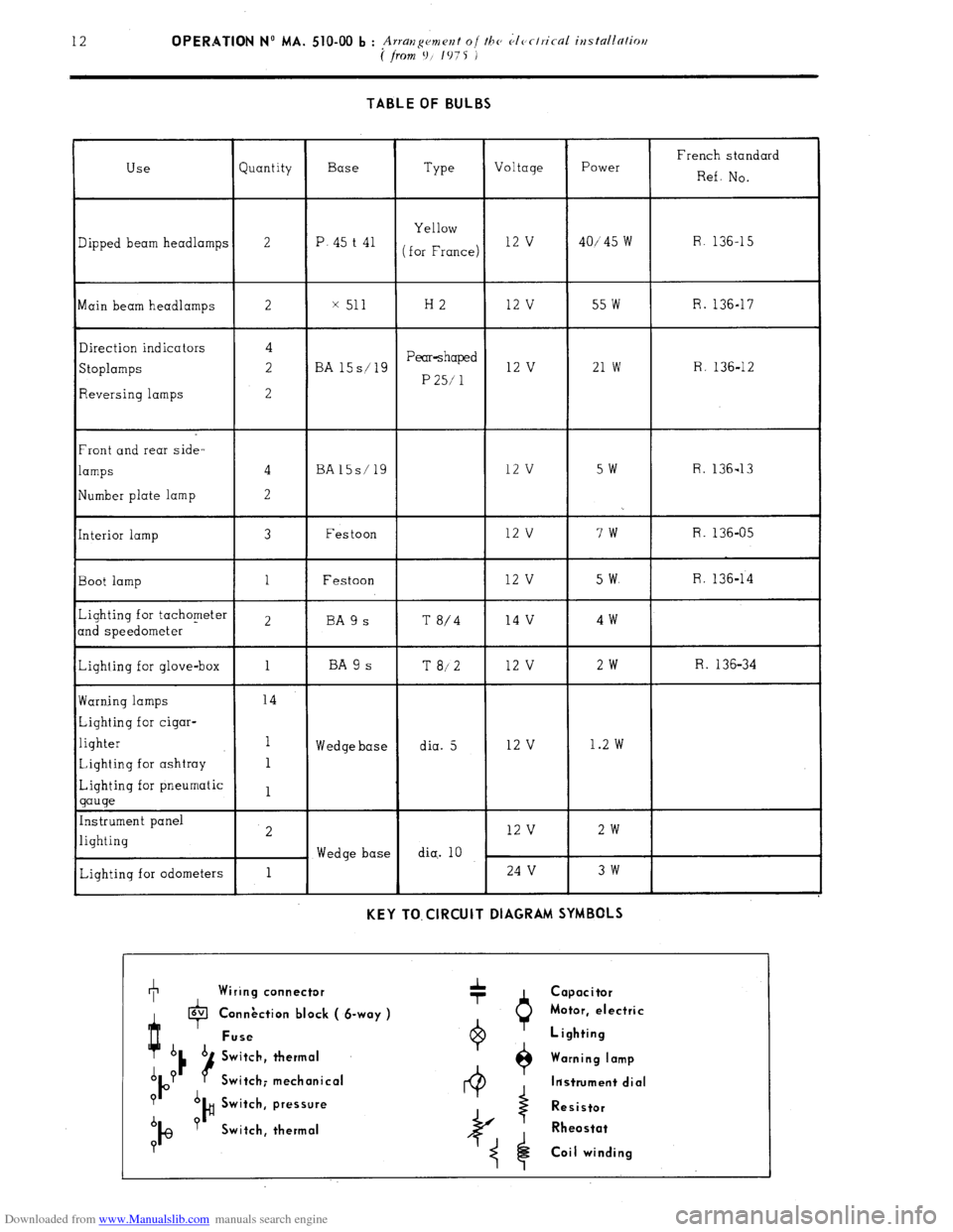
Downloaded from www.Manualslib.com manuals search engine 12 OPERATION No MA. 510-00 b : .A rlan ement oi the CIerlrical iustallatiw
I:
( from 9/ 1075 i
TABLE OF BULBS
Use Quantity Base
Type Voltage Power French standard
Ref. NO.
Yellow
3ipped beam headlamps 2 P. 45 t 41
(for France) 12 v 40/‘45 w R. 136-15
Main beam headlamps 2 x 511 H2 12 v 55 w R. 136-17
Direction indicators 4
Stoplamps 2 BA 15s/19 Pear-shaped 12 v 21 w R. 136-12
P 25/ 1
Reversing lamps 2
Front and rear side-
lamps 4 BA15s/19 12 v SW R. 136-13
!Iumber plate lamp 2
[nterior lamp 3 Festoon 12 v 7w R. 136-05
Boot lamp 1 Festoon 12 v 5 w. R. 136-14
Lighting for tachometer
2 BA 9 s T
md speedometer 8/4 14 v 4w
Lighting for glove-box 1 BA 9 s T 8/2 12 v 2w R. 136-34
Warning lamps 14
Lighting for cigar-
lighter 1
Wedge base dia. 5 12 v 1.2 w
Lighting for ashtray 1
Lighting for pneumatic
1
gauge
Instrument panel
lighting 2 12 v 2w
Wedge base dia.. 10
Lighting for odometers 1 24 v 3w
KEY TO. ClRCUlT DIAGRAM SYMBOLS +
, Wiring connector
I lavl
P
Connection block ( &way ) Connection block ( &way )
Fuse Fuse
A Switch, thermal
A P
P Switch; mechanical Switch; mechanical
? A
b ?
I@ )# Switch, pressure Switch, pressure
Switch, thermal Switch, thermal
? Capacitor
Motor, electric
Lighting
Warning lamp
ltistrument dial
Resistor
Rheostat
Coil winding
Page 329 of 394
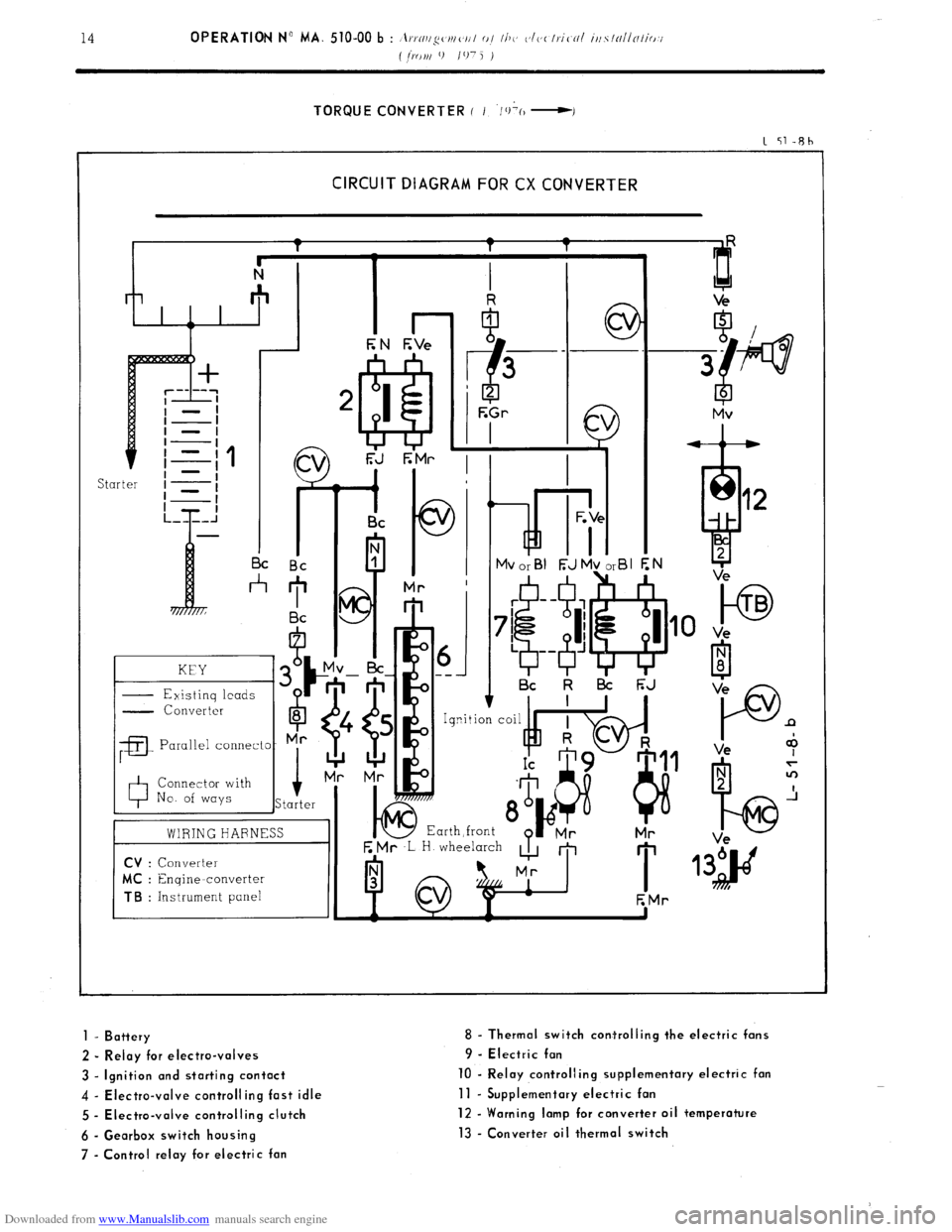
Downloaded from www.Manualslib.com manuals search engine TORQUE CONVERTER ( I ‘/+(I -I
1 51-Rh
CIRCUIT DIAGRAM FOR CX CONVERTER
kd i- I I I c
I I Bc Bc
*
KEY
- Existinq leads G
- Converter
6
8
;a
Parallel connecto- Mr
0 Connector with
No. of ways i
Starter
01 ---
I Bc k l3i F;J
E Mr ,L H wheelarch
A m
I 1
EMr
to TB
Ve
P n
Ve +
1 - Battery
2 - Relay for electro-valves
3 - Ignition and starting contact
4 - Electra-valve controlling fast idle
5 - Electra-valve controlling clutch
6 - Gearbox switch housing
7 - Control relay for electric fan 8 - Thermal switch corrtrolling the electric fans
9 - Electric fan
10 - Relay controlling supplementary electric fan
11 - Supplementary electric fan
12 - Warning lamp for converter oil temperature
13 - Converter oil thermal switch
Page 332 of 394
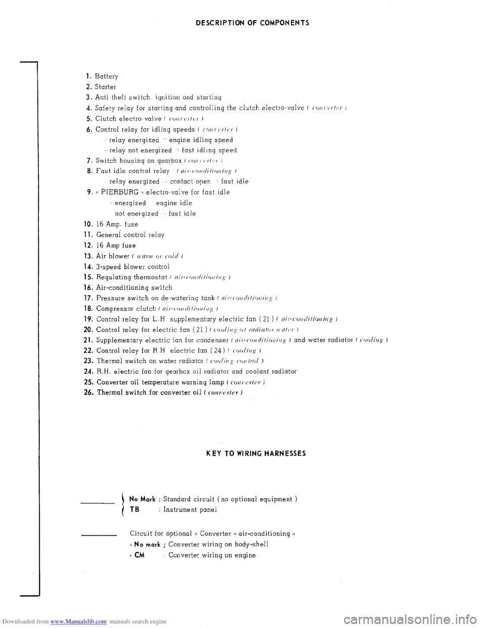
Downloaded from www.Manualslib.com manuals search engine DESCRIPTION OF COMPONENTS
1.
Battery
2. Starter
3. Anti-theft switch ignition and starting
4. Safety relay for starting and controlling the clutch electro-valve f ~/lr,c,r/(,r J
5. Clutch electro-valve ( co,/, V~IO~ J
6. Control relay for idling speeds f W//I r,~/or J
relay energized engine idling speed
- relay not energized 1 fast idling speed
7. Switch housing on gearbox ( WJ,, c,~/(,v J
8. Fast idle control relay / ~i)-c o~r/i/ir~//i,l~ 1
relay energized contact open fast idle
9. (( PIERBURG )) electro-valve for fast idle
- energized engine idle
not energized fast idle
10. I6 Amp. fuse 11.
General control relay 12.
16 Amp fuse 13.
Air blower ( tr’n~r// or c-old ) 14.
3-speed blower control
15. Regulating thermostat ( ~i,.=ror,c/i/irrr,i,l~: i
16. Air-conditioning switch 17.
Pressure switch on de-watering tank f ni,-=( or~rli/irrr/i~~~c ) 18.
Compressor clutch f nifsc o//di/io~i/l~ i 19.
Control relay for L.H supplementary electric fan (21 ) ( ~il..r~l/di/io//il/~ )
20. Control relay for electric fan (21 ) (
coolir~g o/ rficJiNlor (I nlc,r )
21. Supplementary electric fan for condenser ( ~il.~rol/ni/i~~ll/i//~ ) and water radiator ( cooling: J
22. Control relay for R.H electric fan ( 24) ( tooli~!: J
23. Thermal switch on water radiator ( (r)olir~,r~ to~trol )
24. R.H. electric fan for gearbox oil radiator and coolant radiator
25. Converter oil temperature warning lamp ( CM, c~sl~r J
26. Thermal switch for converter oil ( COMWKI~B ) KEY TO WI RING HARNESSES
No Mark
: Standard circuit (no optional equipment ) TB :
Instrument panel
Circuit for optional (( Converter - air-conditioning )) - No mark
; Converter wiring on body-shell
- CM : Converter wiring on engine
Page 333 of 394
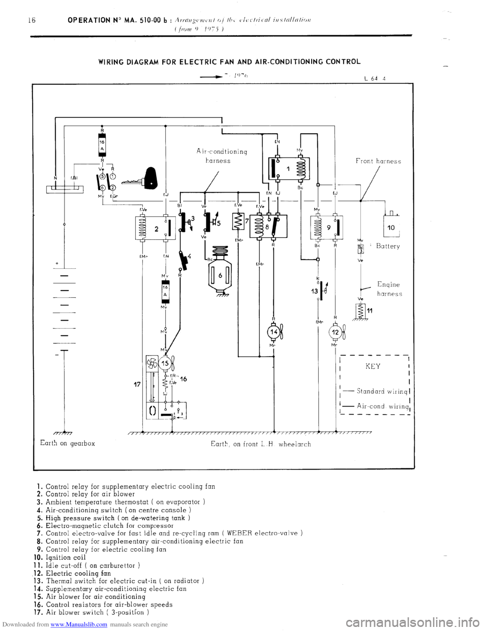
Downloaded from www.Manualslib.com manuals search engine WIRING DIAGRAM FOR ELECTRIC FAN AND AIR-CONDITIONING CONTROL
-- I’)‘(,
L64 4
41 1 1 Front harness
-
T
17
I KEY I
I I
I
Standard wiiinq I
I I
I I
I - Air-cond wiIinq, ‘- - - - - - - _-
1 i 1 1 1
/,/r/////,/,,,,/,//////~////~‘/‘~””’~”””””~””7”“““’
Earth on gearbox
Eart>, on front L H wheelarch 1.
Control relay for supplementary electric cooling fan
2. Control relay for air blower
3. Ambient temperature thermostat ( on evaporator )
4. Air-conditioning switch (on centre console )
5. High pressure switch ( on de-watering tank )
6. Electra-magnetic clutch for compressor
7. Control electro-valve for fast idle and re-cycling ram
( WEBER electro-valve )
8. Control relay for supplementary air-conditioning electric
9. Control relay for electric cooling fan 10.
Ignition coil 11.
Idle cut-off ( on carburettor ) .12.
Electric cooling fan
13. Thermal switch for electric cut-in ( on radiator )
14. Supplementary air-conditioning electric fan
15. Air blower for air- conditioning 16.
Control resistors for air-blower speeds 17.
Air blower switch ( 3-position )